1
SERVICE MANUAL
US Model
Canadian Model
AEP Model
UK Model
E Model
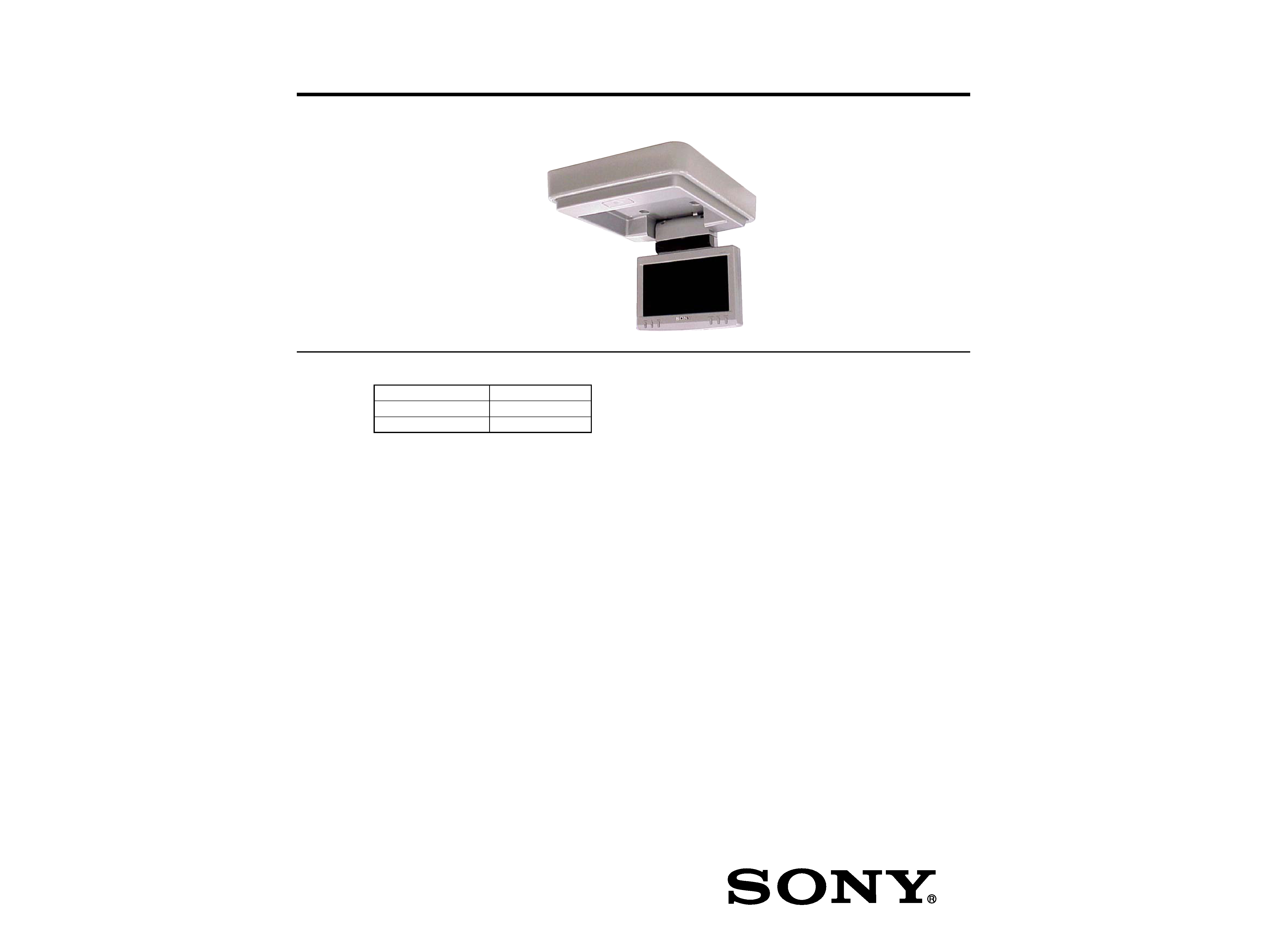
XVM-R70
· This set consists of the following units.
MONITOR
XVM-R70
CONNECTION BOX
XA-115
REMOTE COMMANDER
RM-X122
SPECIFICATIONS
Monitor XVM-R70
System
Liquid crystal color display
Display
Manual flipdown panel
Drive system
TFT-LCD active matrix system
Picture size
7 inches wide screen (16:9)
154
× 87 mm, 176 mm
(6 1/8
× 3 1/2 in., 7 in.) (w/h, d)
Picture segment
336,960 (w 1440
× h 234) dots
Power requirements
12 V DC car battery (negative ground)
Current drain
Approx. 800 mA
Dimensions
230
× 57 × 270 mm
(9 1/8
× 2 3/8 × 10 3/4 in.) (w/h/d)
Operating temperature
5
°C 45 °C (41 °F 113 °F)
Mass
Approx. 1.5 kg (3 lb 5 oz)
Connection box XA-115
A/V Output
Output Impedance: less than 220
less than 100 pF
Output Level:
0 dBs
±0.3 dB (0.775 V rms)
(Vol Max)
Video:
75
1Vp-p
A/V Input
× 3
Input Impedance:
more than 10 K
less than 1000 pF
Input Level:
±1.3 dBs +0/0.3 dB (0.775 V rms)
Video:
75
1 Vp-p
DC output
7.5 V (max 2 A)
Dimensions
150
× 42 × 80 mm
(6
× 1 11/16 × 3 1/4 in.) (w/h/d)
Mass
Approx. 260 g (9 oz)
Card remote commander RM-X122
Power requirements
CR2025 lithium battery
Operable range
Approx. 2.5 m (8.22 ft.)
Dimensions
52
× 125 × 10 mm
(2 1/8
× 5 × 13/32 in.)
(w/h/d)
Mass
Approx. 40 g (1 oz)
(including batteries)
Supplied accessories
Connection box XA-115 (1)
Card remote commander RM-X122
(with supplied battery) (1)
Monitor cable (5 m) (1)
Power supply cord (1)
DC-DC cord (3 m) (1)
Stereo Mini Plug-to-Plug cable (5 m) (1)
Mounting plate (1)
Screws (4)
Tapping Screws (4)
Operating Instructions (1)
Design and specifications are subject to change
without notice.
Ver. 1.2 2005.07
9-961-143-03
2005G04-1
© 2005.07
OVERHEAD MONITOR
Sony Corporation
e Vehicle Group
Published by Sony Engineering Corporation

2
Notes on Chip Component Replacement
·Never reuse a disconnected chip component.
· Notice that the minus side of a tantalum capacitor may be
damaged by heat.
XVM-R70
SAFETY-RELATED COMPONENT WARNING!!
COMPONENTS IDENTIFIED BY MARK 0 OR DOTTED LINE
WITH MARK 0 ON THE SCHEMATIC DIAGRAMS AND IN
THE PARTS LIST ARE CRITICAL TO SAFE OPERATION.
REPLACE THESE COMPONENTS WITH SONY PARTS WHOSE
PART NUMBERS APPEAR AS SHOWN IN THIS MANUAL OR
IN SUPPLEMENTS PUBLISHED BY SONY.
ATTENTION AU COMPOSANT AYANT RAPPORT
À LA SÉCURITÉ!!
LES COMPOSANTS IDENTIFIÉS PAR UNE MARQUE 0 SUR LES
DIAGRAMMES SCHÉMATIQUES ET LA LISTE DES PIÈCES SONT
CRITIQUES POUR LA SÉCURITÉ DE FONCTIONNEMENT. NE
REMPLACER CES COMPOSANTS QUE PAR DES PIÈCES SONY
DONT LES NUMÉROS SONT DONNÉS DANS CE MANUEL OU
DANS LES SUPPLÉMENTS PUBLIÉS PAR SONY.
5-10. IR Transmitter Check ....................................................... 15
5-11. V COM Voltage/Position Adjustment .............................. 16
5-12. Video Adjustment ............................................................. 16
5-12-1. Brightness Signal Contrast Level (Y GAIN) ......... 16
5-12-2. Black Limiter Level Adjustment ............................ 16
5-12-3. White Limiter Level Adjustment ........................... 16
5-12-4. R Sub Brightness Adjustment ................................ 16
5-12-5. B Sub Brightness Adjustment ................................ 16
5-12-6. R Sub Contrast Adjustment ................................... 17
5-12-7. B Sub Contrast Adjustment ................................... 17
5-12-8.
1 Adjustment ....................................................... 17
5-12-9.
2 Adjustment ....................................................... 17
5-12-10. VCO Free Run Adjustment .................................... 17
5-12-11. V POS Adjustment ................................................. 17
5-12-12. H POS Adjustment ................................................. 17
6. DIAGRAMS
6-1. IC Pin Description ............................................................ 19
6-2. Block Diagram Video Section ...................................... 21
6-3. Block Diagram Display Section ................................... 22
6-4. Printed Wiring Board LCD Section (1/2) .................... 24
6-5. Printed Wiring Board LCD Section (2/2) .................... 25
6-6. Printed Wiring Board Base Section (1/2) ..................... 26
6-7. Printed Wiring Board Base Section (2/2) ..................... 27
6-8. Schematic Diagram LCD Section (1/3) ....................... 28
6-9. Schematic Diagram LCD Section (2/3) ....................... 29
6-10. Schematic Diagram LCD Section (3/3) ....................... 30
6-11. IC Block Diagrams .......................................................... 31
7. EXPLODED VIEWS
7-1. Base (1) Section ............................................................... 34
7-2. Base (2) Section ............................................................... 35
7-3. LCD Section ..................................................................... 36
7-4. Connection Box Section (XA-115) .................................. 37
8. ELECTRICAL PARTS LIST ....................................... 38
1. SERVICING NOTES ....................................................... 3
2. GENERAL
Location of Controls ............................................................... 4
Connection diagram ............................................................... 6
3. DISASSEMBLY
3-1. Skirt (Base) ........................................................................ 8
3-2. Base Board ......................................................................... 8
3-3. SW Board ........................................................................... 9
3-4. Covers (Hinge) ................................................................... 9
3-5. LCD Block Assy .............................................................. 10
3-6. Case (LCD Rear) .............................................................. 10
3-7. Chassis (LCD) .................................................................. 11
3-8. LCD Board ....................................................................... 12
3-9. LCD1 ................................................................................ 12
4. TEST MODE .................................................................... 13
5. ELECTRICAL ADJUSTMENTS
5-1. Equipment Used ............................................................... 14
5-2. Connection of Equipment ................................................ 14
5-3. Setup for Adjustment ....................................................... 14
5-4. DC-DC Converter Adjustment ......................................... 15
5-4-1. Frequency Adjustment ............................................. 15
5-4-2. 5V Voltage Adjustment ............................................ 15
5-4-3. Other Voltage Checks ............................................... 15
5-5. PLL Adjustment ............................................................... 15
5-5-1. Frequency Adjustment ............................................. 15
5-5-2. Frequency Check ..................................................... 15
5-6. Inverter High Voltage Check ............................................ 15
5-6-1. Voltage Check .......................................................... 15
5-6-2. Frequency Check ..................................................... 15
5-7. OSD Dot Clock Check ..................................................... 15
5-8. NTSC Subcarrier Check .................................................. 15
5-9. PAL Subcarrier Check ...................................................... 15
TABLE OF CONTENTS
3
XVM-R70
SECTION 1
SERVICING NOTES
NOTE FOR REPLACEMENT OF THE EEP ROM (IC402)
The EEP ROM (IC402) contains all data by which the LCD screen is defined.
When the EEP ROM is replaced, the normal LCD screen will not appear.
It is then necessary to write the data into the EEP ROM.
Writing Method:
1. Place the POWER SELECT switch on the set into the B position.
2. Turn power on. While holding the RESET key down, depress the R key.
Then release the RESET key and the R key in this order.
3. Press the VOL key on the remote controller for more than 2 seconds.
4. The EEP ROM data will be written and the normal test mode screen will appear.
After this, perform V COM voltage/position adjustment as well as VIDEO adjustment.
NOTE FOR REPLACEMENT OF THE SYSTEM CONTROL (IC400)
When the IC400 is replaced, the video system should be set again according to the destinations.
Setting Method:
1. Enter the test mode. (See page 13).
2. Select NTSC/PAL SELECT from the test mode menu.
3. Set the video system to the appropriate mode for each destination by using the R and r keys on the remote controller.
Video mode
Destination
NTSN
US, Canadian
NTSC DVD PACK
*MV-7101DS
PAL
E
PAL DVD PACK
AEP, UK
* MV-7101DS represents the MV-7101DS package monitor.
Ver 1.1
4
XVM-R70
SECTION 2
GENERAL
This section is extracted
from instruction manual.
7
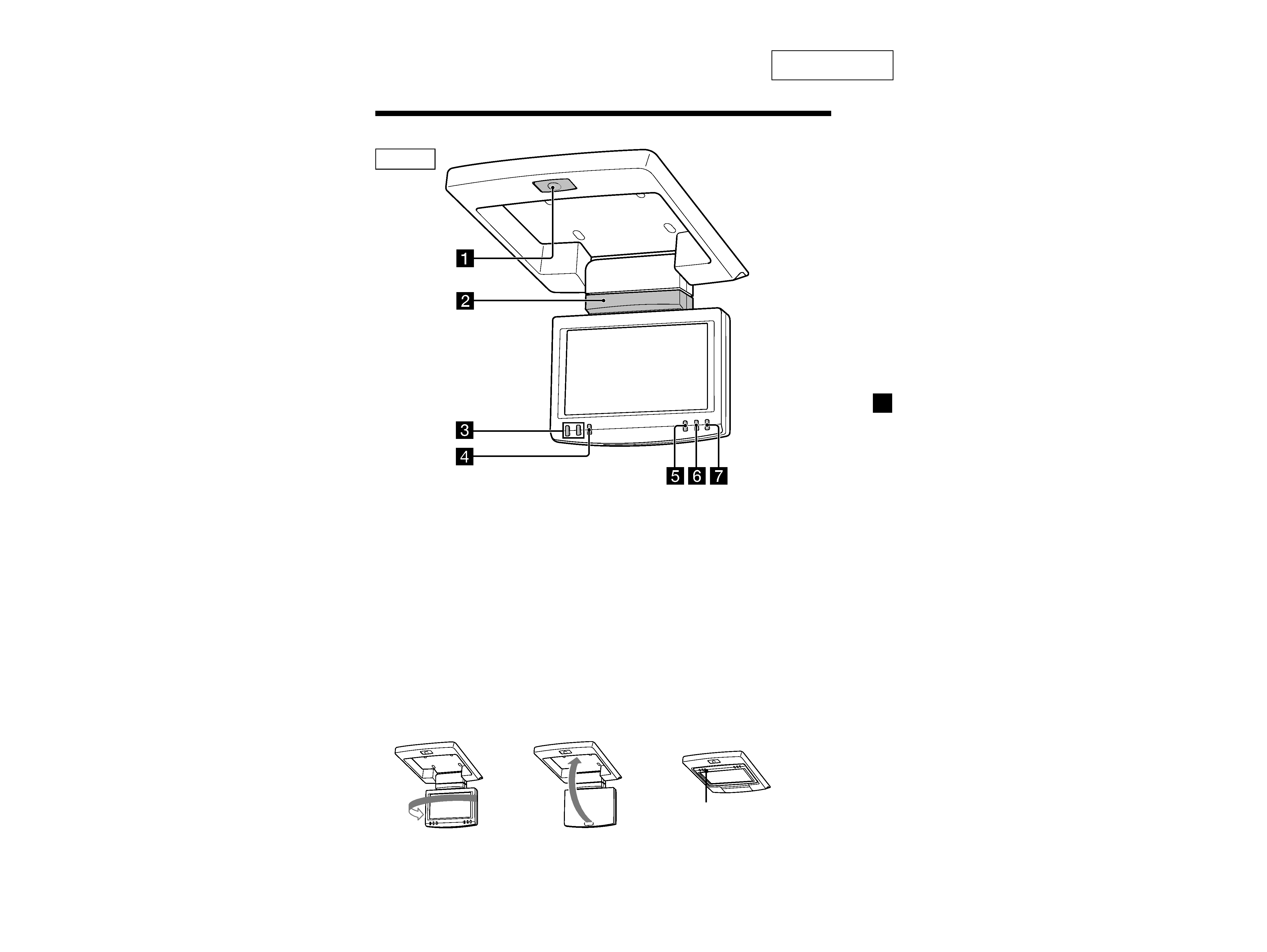
Location of controls
1 OPEN button
Press to open the monitor.
2 Receptor for the card remote
commander/Transmitter for the
cordless headphones
3 UP/DOWN (M/m) buttons
Press to select the desired item.
Monitor
continue to next page t
* The reverse position of the display monitor
You can close with the LCD surface out after turning around 180 degrees, and images on
the screen can be turned upside down by pressing (REVERSE) on the monitor. Before
closing the display monitor, make sure that the monitor is turned and facing the
enclosure (you will hear a click). Each time you press (REVERSE) on the monitor, the
reverse screen mode switches between on and off.
4 MENU button
Press to adjust the various display
settings.
5 REVERSE button*
Press to switch images upside down.
6 INPUT button
Press to select the input source.
7 POWER button
REVERSE
180°
c
c
55
XVM-R70
8
AT T
POWER
MENU
INPUT
MODE
LIST
SETUP
TOP MENU ALBUM
+
ALBUM
MENU
DISPLAY
ENTER
VOL
SUBTITLE
AUDIO
OFF
AT T
POWER
MENU
INPUT
MODE
LIST
SETUP
TOP MENU ALBUM
+
ALBUM
MENU
DISPLAY
ENTER
VOL
SUBTITLE
AUDIO
OFF
Tip
Refer to "Replacing the lithium battery" for details on how to replace the batteries (page 18).
For the monitor operations:
1 ATT button
Press to quickly attenuate the
volume.
2 VOL (volume) +/ buttons
Press to adjust the volume.
3 INPUT button
Press to select the input source.
4 POWER button
5 MENU button
Press to adjust the various display
settings.
6 MODE button
Press to change the screen mode.
7 V/v buttons
Press to select the desired item.
Card remote commander RM-X122
For DVD operations:
When a Sony mobile DVD player is
connected to this unit, you can control
the basic functions with the card remote
commander.
8 V/v (ALBUM +/) buttons
9 TOP MENU button
0 MENU button
qa O button
qs ./> buttons
qd m/M (
) buttons
qf B/b buttons
qg LIST button
qh SET UP button
qj ENTER button
qk DISPLAY button
ql u button
w; OFF button
wa SUBTITLE button
ws AUDIO button
·For function details, refer to the
operating instructions supplied with the
DVD player.
· Sony DVD changer DVX-100 is not
controllable with this card remote
commander.