1
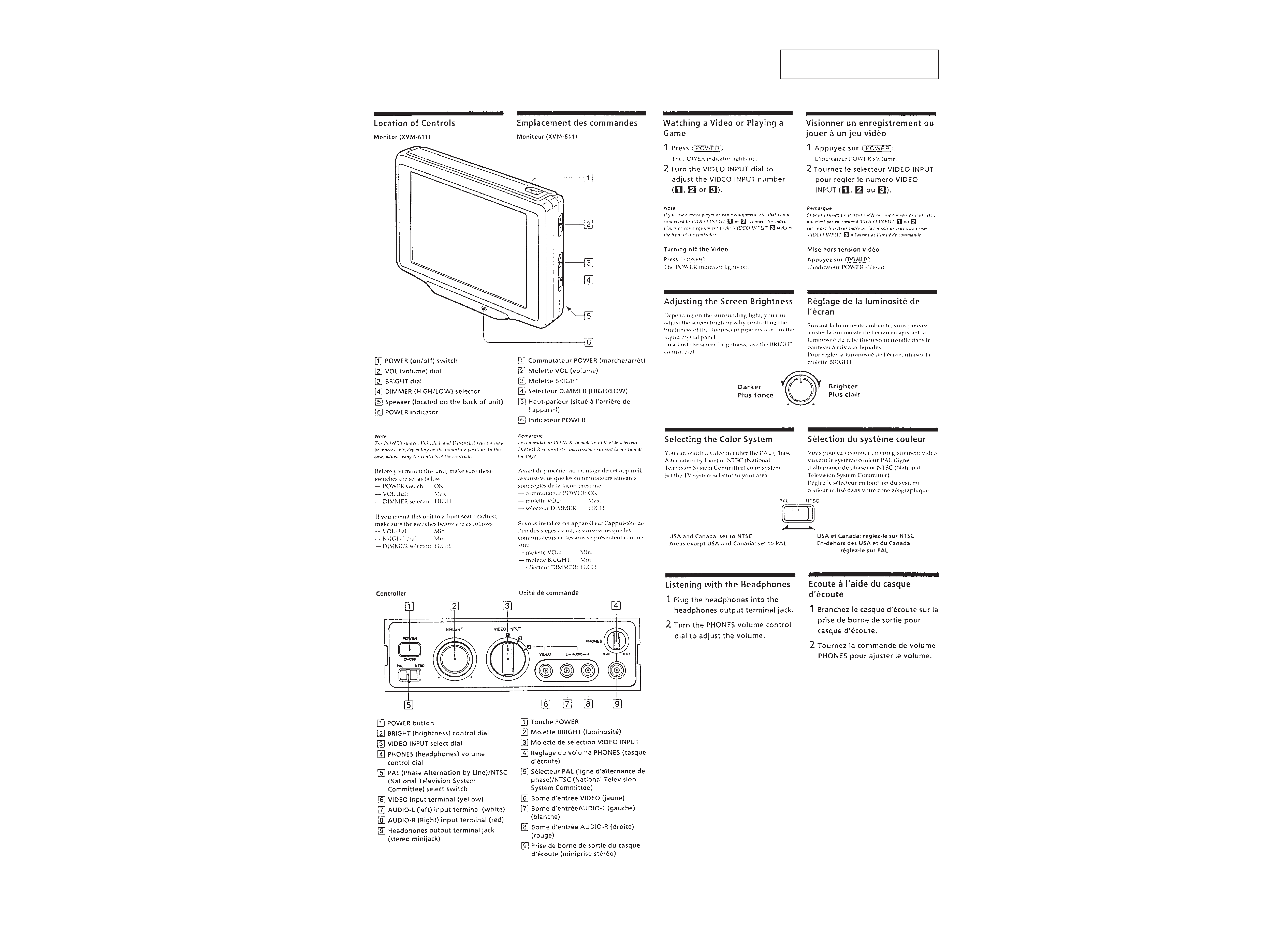
Supplied accessories
Controller (RM-X6100) (1) (XVM-6100 only)
Monitor cable (1)
Hideaway unit (XA-602) (1) (XVM-61EX only)
Video selector (XA-601) (1) (XVM-6100 only)
Design and specifications are subject to change
without notice.
SERVICE MANUAL
US Model
XVM-6100
UK Model
E Model
German Model
XVM-61EX
XVM-61EX/6100
EXTENSION MONITOR SYSTEM
Monitor (XVM-611/611EX)
System
Liquid crystal color display
Display
Transparent TN LCD panel
Drive system
TFT active matrix system
Picture size
6 in. ; 121.9
× 89.2 mm (4 7/8
× 3 5/8 in.), 151 mm (6 in.)
(w
× h, diagonally)
Picture segment
224,640 (w 960
× h 234)
Speaker type
ø 5 cm (ø 2 in.) dynamic
speaker
Power requirements
12 V DC car battery
(negative ground)
Current drain
Approx. 0.7 A
Dimensions
162
× 129 × 31 mm (6 1/2 ×
5 1/8
× 1 1/4 in.) (w × h × d)
Operating temperature
+5 °C ~ +45 °C
(41 °F ~ 113 °F)
Mass
Approx. 430 g (15.3 oz.)
Controller (RM-X6100) (XVM-6100 only)
Dimensions
178
× 50 × 40 mm (6 1/2 ×
2
× 1 1/4 in.) (w × h × d)
Operable range
Approx. 3 m (118 1/4 in.)
Mass
Approx. 400 g (14.1 oz.)
(including cable)
SPECIFICATIONS
MICROFILM
Notes on Chip Component Replacement
· Never reuse a disconnected chip component.
· Notice that the minus side of a tantalum capacitor may be
damaged by heat.
Photo : XVM-611EX (Monitor)
XVM-61EX
XVM-6100
MONITOR
XVM-611EX
XVM-611
VIDEO SELECTOR
XA-601
CONTROLLER
RM-X6100
HIDEAWAY UNIT
XA-602
· This set consists of the following units.
XVM-6100
XVM-61EX
MOBILE COLOR MONITOR SYSTEM

2
TABLE OF CONTENTS
1. GENERAL .......................................................................... 3
2. ELECTRICAL ADJUSTMENTS
Monitor Section ...................................................................... 4
Video Selector Section (XVM-6100 only) ............................. 6
3. DIAGRAMS
3-1. Block Diagram
Monitor Section (XVM-611/611EX) ........................... 7
3-2. Block Diagram Video Selector Section (XA-601) ....... 9
3-3. Block Diagram Hideaway Unit Section (XA-602) .... 10
3-4. Block Diagram Controller Section (RM-X6100) ....... 11
3-5. Printed Wiring Board
Monitor Section (XVM-611/611EX) ......................... 13
3-6. Schematic Diagram
Monitor Section (XVM-611/611EX) ......................... 17
3-7. Schematic Diagram
Video Selector Section (XA-601) .............................. 22
3-8. Printed Wiring Board
Video Selector Section (XA-601) .............................. 25
3-9. Schematic Diagram
Hideaway Unit Section (XA-602) .............................. 28
3-10. Printed Wiring Board
Hideaway Unit Section (XA-602) .............................. 31
3-11. Printed Wiring Board
Controller Section (RM-X6100) ................................ 33
3-12. Schematic Diagram
Controller Section (RM-X6100) ................................ 35
4. EXPLODED VIEWS
4-1. Monitor Section (XVM-611/611EX) ............................... 39
4-2. Video Selector Section (XA-601) .................................... 40
4-3. Controller Section (RM-X6100) ...................................... 41
4-4. Hideaway Unit Section (XA-602) .................................... 42
5. ELECTRICAL PARTS LIST ................................... 43
3
SECTION 1
GENERAL
This section extracted from
XVM-6100's instruction manual.
4
SECTION 2
ELECTRICAL ADJUSTMENTS
Equipment
Use the following test equipment for alignment.
· Oscilloscope dual trace, 10 MHz band or above with delay mode
(use a 10 to 1 probe unless otherwise instructed.)
· NTSC color bar generator
· PAL color bar generator
· DC power supply
· Digital voltmeter
· XT-61VE (TV tuner unit of XTL-610E) (XVM-61EX only)
· Frequency counter
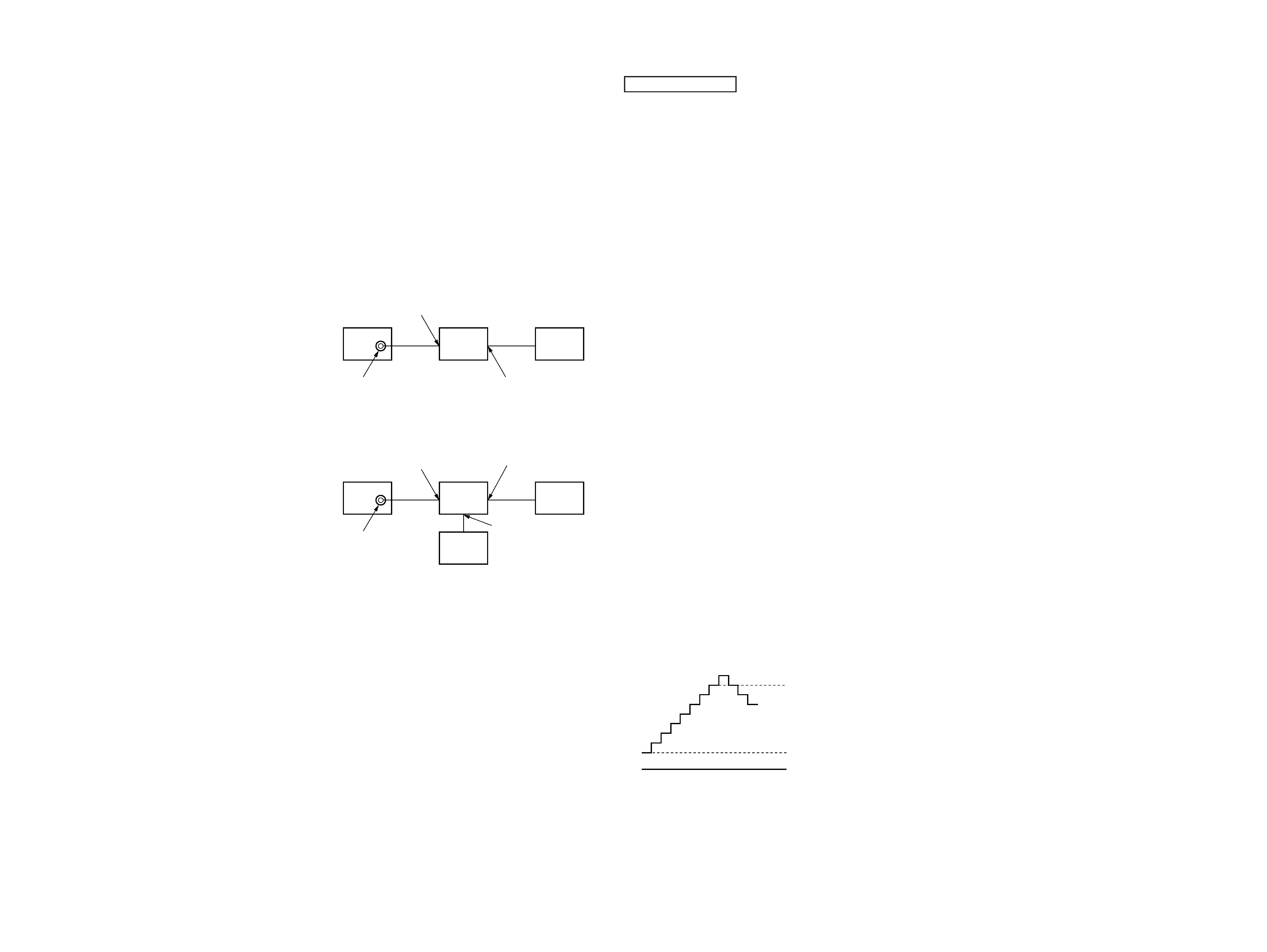
Equipment Connections
Make the test equipment connections as shown below (unless
instructed otherwise) and perform the alignment.
XVM-61EX :
NAVI INPUT
(VIDEO)
color bar
generator
XT-61VE
XVM-611EX
VIDEO output
(75
)
MONITOR OUTPUT
INPUT 1
(VIDEO)
MONITOR OUTPUT
CONTROLLER
XA-601
XVM-611
color bar
generator
VIDEO output
(75
)
RM-X6100
XVM-6100 :
MONITOR SECTION
Voltage Adjustment
Setting :
DIMMER selector (S701) : HIGH
BRIGHT dial (RV702)
: Max. (light)
VOL dial (RV301)
: Max.
Procedure :
1. Input the color bar (chroma off) signal from NTSC color bar
generator and display on the monitor screen.
2. Connect the digital voltmeter to CL66 on the monitor main
board.
3. Adjust RV401 (+5V) so that the digital voltmeter reads 5
±0.1 V
DC.
4. Connect the digital voltmeter to CL86 on the monitor main
board.
5. Adjust RV601 (+9V) so that the digital voltmeter reads 8.5
±0.1 V
DC.
Connection points : Monitor main board Refer to page 5.
Alignment points : Monitor main board Refer to page 5.
RGB Adjustment
Procedure :
1. Input the color bar (chroma off) signal from NTSC color bar
generator and display on the monitor screen.
2. Connect the digital voltmeter to CL151 on the monitor main
board.
3. Adjust RV213 (OFFSET) so that the digital voltmeter reads
2.3
±0.1 V DC.
4. Connect the oscilloscope to CL42 on the monitor main board.
5. Adjust RV212 (COM CUT) so that the lower black level is
6.2
±0.05 V DC.
6. Adjust RV208 (COM DRIVE) so that the upper 100% white
level is 9.2
±0.05 V DC.
7. Repeat steps 5 & 6 until the items in the standards are satisfied.
8. Connect the oscilloscope to CL41 of the monitor main board.
9. Adjust RV207 (R DRIVE) so that the lower black level is
6.2
±0.05 V DC.
10. Adjust RV202 (R CUT) so that the upper 100% white level is
9.2
±0.05 V DC.
11. Repeat steps 9 & 10 until the items in the standards are satisfied.
12. Connect the oscilloscope to CL43 of the monitor main board.
13. Adjust RV209 (B DRIVE) so that the upper 100% white level
is 6.1
±0.05 V DC.
14. Adjust RV204 (B CUT) so that the upper 100% white level is
9.1
±0.05 V DC.
15. Repeat steps 13 & 14 until the items in the standards are satisfied.
1
2
3
4
5
6
7
8
white level (1st step)
black level (8th step)
0 V
Connection points : Monitor main board Refer to page 5.
Alignment points : Monitor main board Refer to page 5.
5
6
V COM Adjustment
Procedure :
1. Connect the oscilloscope to CL44 on the monitor main board.
2. Adjust RV210 (V COM AMP) & RV211 (V COM BIAS) so
that the output waveform is within the standards.
3. Repeat step 2 until the standards are satisfied.
Standard values :
A : Adjust RV210 so the value is 4.9
±0.1 Vp-p.
B : Adjust RV211 so the value is 5.1
±0.1 V.
A
B
0 V
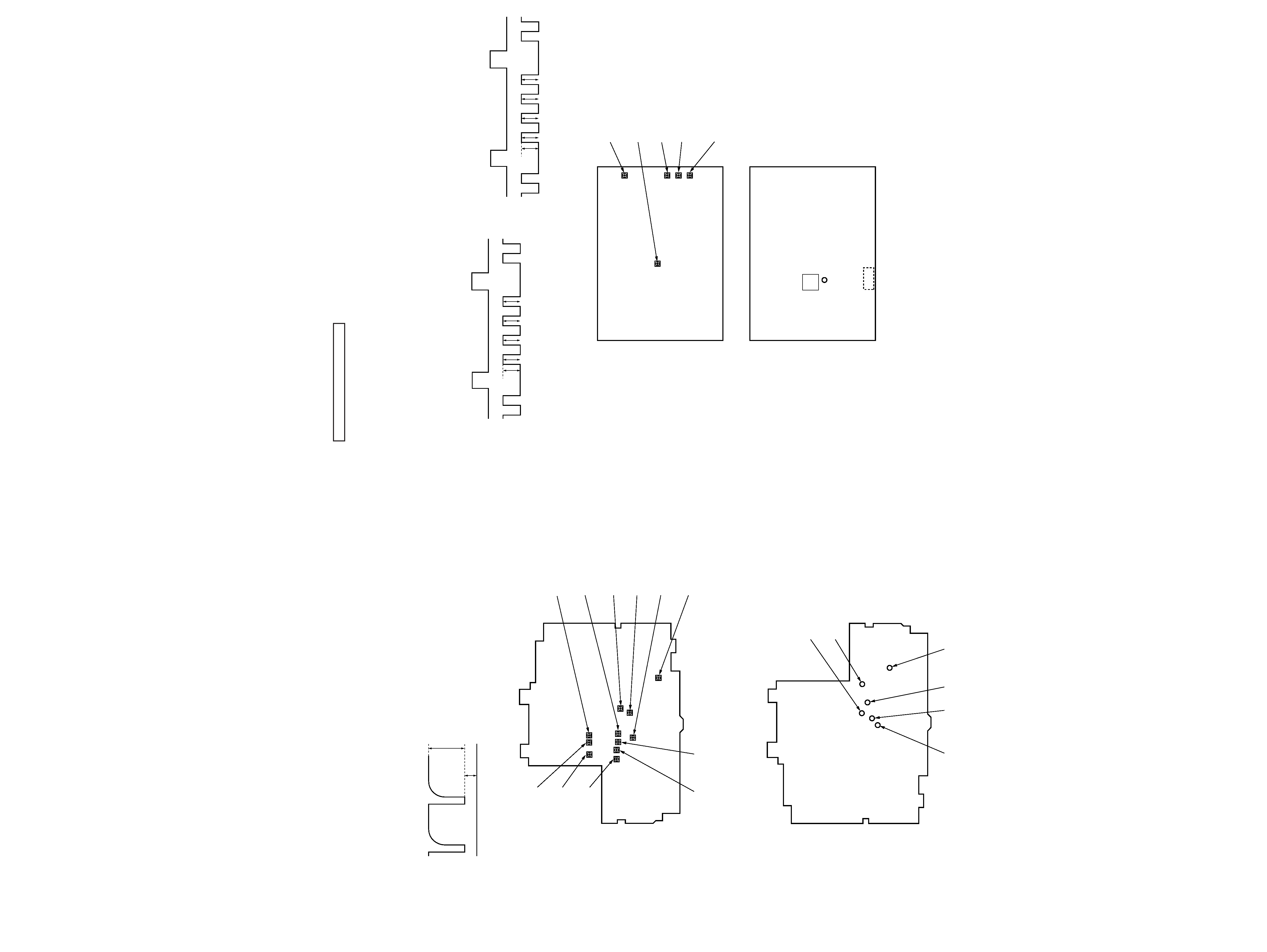
Connection points : Monitor main board
RV207
R DRIVE
ADJ
RV208
COM DRIVE
ADJ
RV213
OFFSET
ADJ
RV212
COM CUT
ADJ
RV202
R CUT
ADJ
RV209
B DRIVE ADJ
RV204
B CUT ADJ
RV210
V COM AMP ADJ
RV211
V COM BIAS ADJ
RV401
+5V ADJ
RV601
+9V ADJ
MONITOR MAIN BOARD (COMPONENT SIDE)
MONITOR MAIN BOARD (CONDUCTOR SIDE)
CL44
CL43
CL41
CL66
CL42
CL151
Alignment points : Monitor main board
VIDEO SELECTOR SECTION (XVM-6100 only)
NTSC Adjustment
Procedure :
1. Input the color bar signal from NTSC color bar generator on
the AV selector board.
2. Connect the frequency counter to TP61 (SC OUT).
3. Confirm reading the frequency counter is 3.579545 MHz.
4. Connect the oscilloscope to CN3 !£ pin (B OUT).
5. Adjust RV1 (Y.C ADJ) so that white peak (100% white) is
1.00 Vp-p.
6. Adjust RV2 (HUE ADJ) and RV3 (COL ADJ) so that amplitude
of each color is same (A=B=C=D).
PAL Adjustment
Procedure :
1. Input the color bar signal from PAL color bar generator on the
AV selector board.
2. Connect the frequency counter to TP61 (SC OUT).
3. Confirm reading the frequency counter is 4.433619 MHz.
4. Connect the digital voltmeter to IC10 !¢ pin (DLA BIAS).
5. Adjust RV5 (DLA BIA ADJ) so that reading the digital voltmeter
is 2.3 V.
6. Adjust RV1 (Y.C ADJ) so that white peak (100% white) is
1.00 Vp-p.
7. Adjust RV2 (HUE ADJ) and RV3 (COL ADJ) so that amplitude
of each color is same (A=B=C=D).
Alignment points : AV selector board
AB
C
D
1 Vp-p
SYNC
OUT
B OUT
AB
C
D
1 Vp-p
SYNC
OUT
B OUT
AV SELECTOR BOARD (COMPONENT SIDE)
AV SELECTOR BOARD (CONDUCTOR SIDE)
RV1
Y.C ADJ
RV3
COL ADJ
RV4
APC ADJ
RV2
HUE ADJ
RV5
DLA BIA ADJ
IC10
CN3
TP61
(SC OUT)
Connection points : AV selector board