MICROFILM
XR-T200
FM/AM CASSETTE CAR STEREO
SERVICE MANUAL
Saudi Arabia Model
Model Name Using Similar Mechanism
XR-1750
Tape Transport Mechanism Type
MG-52A-135
· XR-T200 are almost same as XR-1750.
Printed wiring boards, schematic diagram, exploded views
and electrical parts list are described in this service manual.
Please refer to XR-1750 service manual previously issued
for the other informations.
TABLE OF CONTENTS
1.
EXPLODED VIEWS ................................................ 2
2.
DIAGRAMS
2-1. IC Pin Function Description ........................................... 6
2-2. Printed Wiring Boards MAIN Section ....................... 8
2-3. Schematic Diagram MAIN Section ........................... 11
2-4. Printed Wiring Board CONTROL Section ................ 15
2-5. Schematic Diagram CONTROL Section ................... 17
3.
ELECTRICAL PARTS LIST ............................... 19
SERVICING NOTES
Flexible Circuit Board Repairing
· Keep the temperature of the soldering iron around 270 °C dur-
ing repairing.
· Do not touch the soldering iron on the same conductor of the
circuit board (within 3 times).
· Be careful not to apply force on the conductor when soldering
or unsoldering
Notes on chip component replacement
· Never reuse a disconnected chip component.
· Notice that the minus side of a tantalum capacitor may be dam-
aged by heat.
2
NOTE:
· -XX and -X mean standardized parts, so they
may have some difference from the original
one.
· Color Indication of Appearance Parts
Example:
KNOB, BALANCE (WHITE) . . . (RED)
Parts Color
Cabinet's Color
· Items marked "*" are not stocked since they
are seldom required for routine service. Some
delay should be anticipated when ordering
these items.
· The mechanical parts with no reference num-
ber in the exploded views are not supplied.
· Hardware (# mark) list and accessories and
packing materials are given in the last of the
electrical parts list.
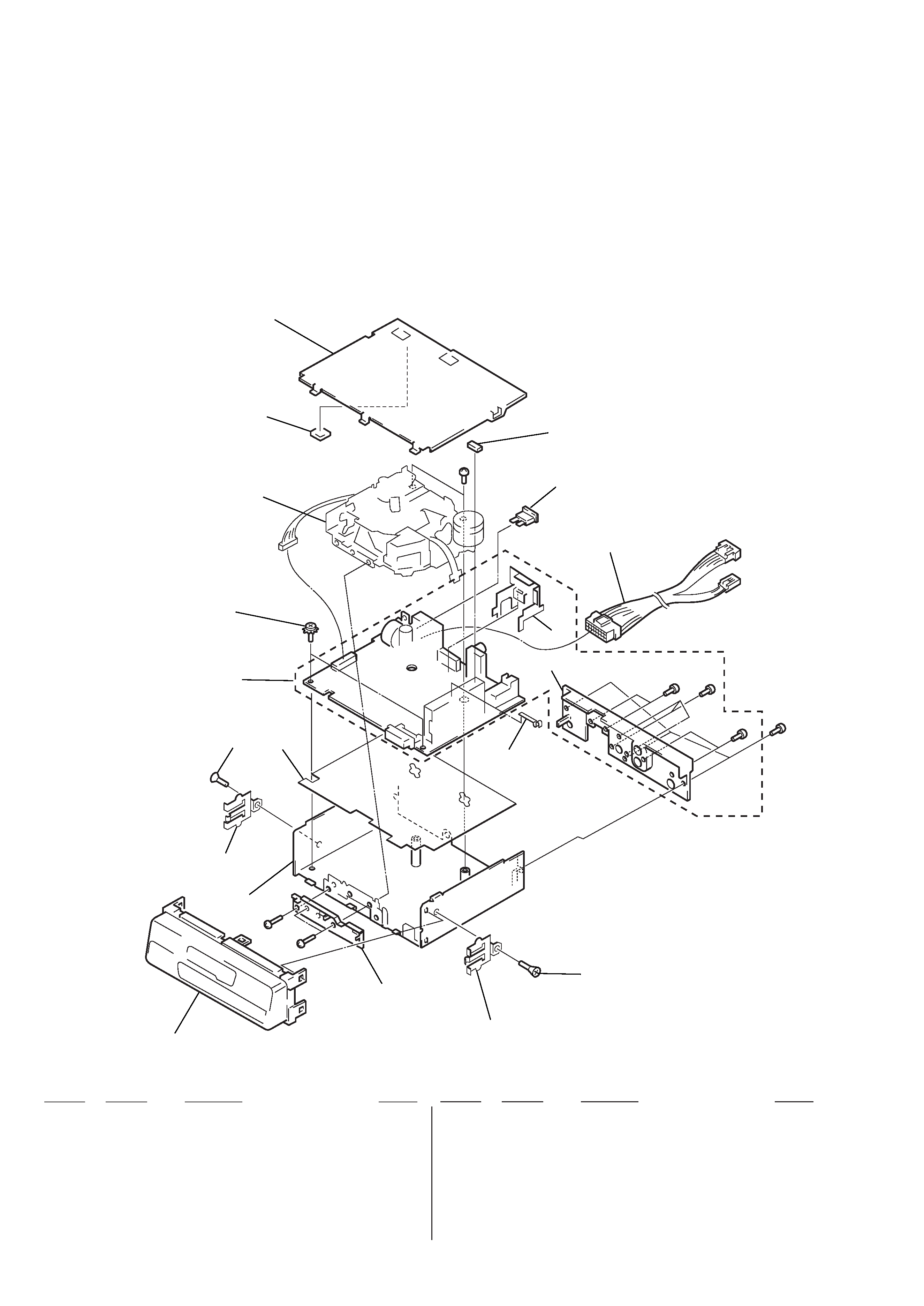
SECTION 1
EXPLODED VIEWS
(1) CHASSIS SECTION
Ref. No.
Part No.
Description
Remark
Ref. No.
Part No.
Description
Remark
* 1
X-3373-606-1 CHASSIS ASSY
* 2
3-012-600-01 INSULATOR
* 3
A-3313-260-A MAIN BOARD, COMPLETE
4
3-915-923-01 SCREW, GROUND POINT
* 5
3-012-565-01 COVER
6
1-777-184-11 CORD (WITH CONNECTOR)
* 7
3-012-598-01 BRACKET (IC)
* 8
3-012-599-01 HEAT SINK
9
3-937-650-01 PLATE (C), GROUND
10
3-934-325-01 SCREW, +K (5X8) TAPPING
11
3-935-568-01 BRACKET (LOCK)
12
9-911-840-XX CUSHION (U)
* 13
3-014-628-01 CHASSIS, FRONT
F901
1-533-330-11 FUSE (BLADE TYPE) (AUTO FUSE) (10A)
5
6
not
supplied
MG-52A-135
4
3
2
10
11
1
13
11
10
#1
#1
Front panel ass'y
12
#1
F901
9
8
7
#2
#2
#2
#4
3
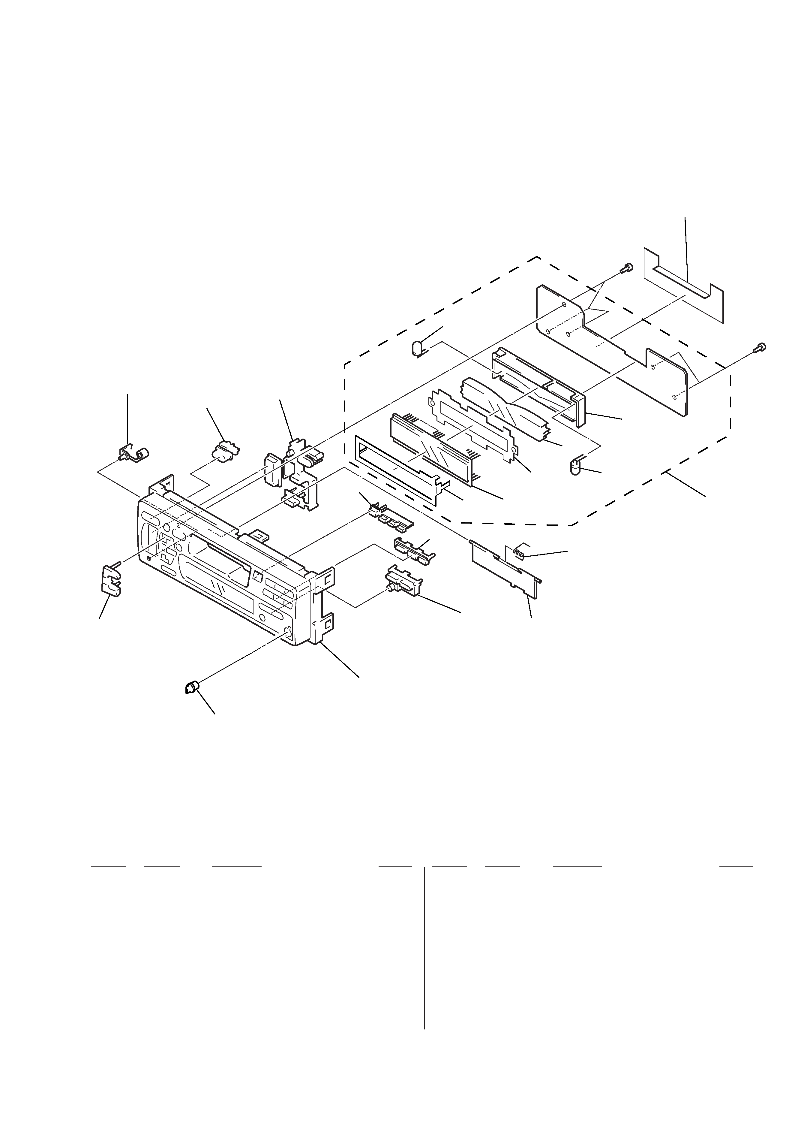
(2) FRONT PANEL SECTION
Ref. No.
Part No.
Description
Remark
Ref. No.
Part No.
Description
Remark
51
3-009-301-01 BUTTON (BASS)
53
3-009-299-01 BUTTON (L) (2) (+.)
55
3-012-576-01 BUTTON (RESET)
56
3-009-300-01 BUTTON (SOURCE)
57
3-009-297-01 BUTTON (L) (
r. OFF. + + ). .
SEEK AMS.
= 0 . SEL. MUTE)
58
3-009-308-01 BUTTON (1-3) (
6. 1. 2. 3)
59
3-009-309-11 BUTTON (4-6) (4. 5. 6)
60
3-009-313-01 BUTTON (R) (S) (BTM. LCL.
r)
61
3-932-205-81 DOOR, CASSETTE
62
3-935-003-01 SPRING, TORSION
* 63
3-010-282-01 PLATE (LCD), GROUND
* 64
3-012-669-01 SHEET (REFLECTOR)
* 65
3-009-302-01 PLATE (LCD), LIGHT GUIDE
* 66
3-009-303-02 HOLDER (LCD)
* 67
A-3294-317-A CONTROL BOARD, COMPLETE
68
X-3374-314-1 PANEL SUB ASSY
LCD901 1-801-678-11 DISPLAY PANEL, LIQUID CRYSTAL
PL901
1-517-567-11 LAMP, PILOT
PL902
1-517-567-11 LAMP, PILOT
not supplied
#3
#3
PL902
LCD901
PL901
67
66
65
64
63
58
59
60
61
68
51
53
55
56
57
62
4
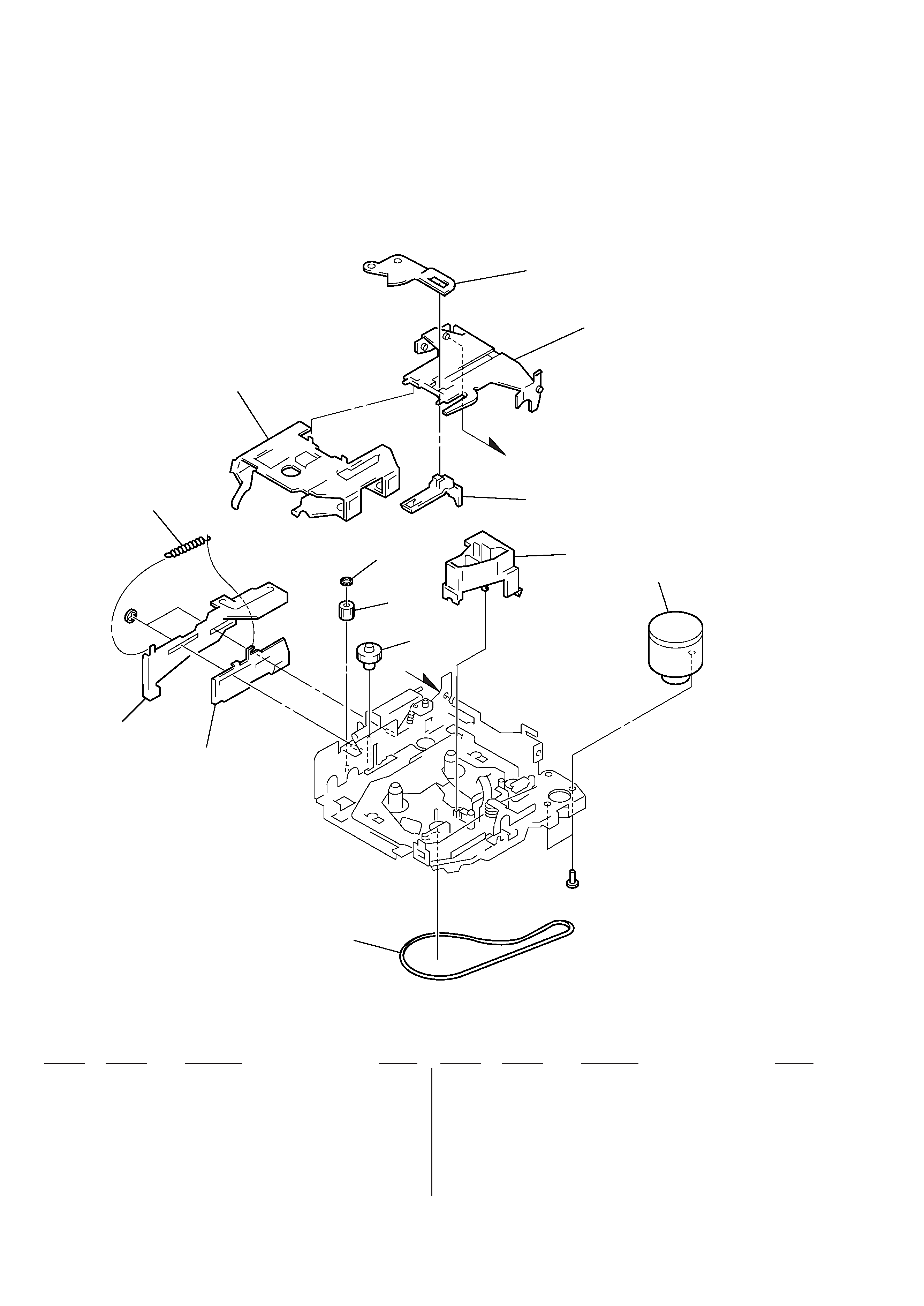
(3) MECHANISM DECK SECTION-1
(MG-52A-135)
Ref. No.
Part No.
Description
Remark
Ref. No.
Part No.
Description
Remark
101
3-928-675-01 BELT (52)
* 102
3-928-673-01 LEVER (LDG-A)
103
3-928-674-01 LEVER (LDG-B)
104
3-933-341-01 SPRING (LEVER LDG), TENSION
105
3-928-671-01 HOUSING
* 106
3-933-347-01 ARM (SUCTION)
107
3-933-340-01 HANGER
108
3-933-346-01 CATCHER
109
3-933-344-01 GUIDE (C)
110
3-341-753-11 WASHER, POLYETHYLENE
111
3-933-335-01 GEAR (LDG-FT)
112
3-928-667-01 GEAR (LDG-A)
M901
A-3291-665-A MOTOR ASSY, MAIN (CAPSTAN/REEL)
106
107
108
109
A
M901
110
111
112
101
102
103
104
105
A
#
6
#7
5
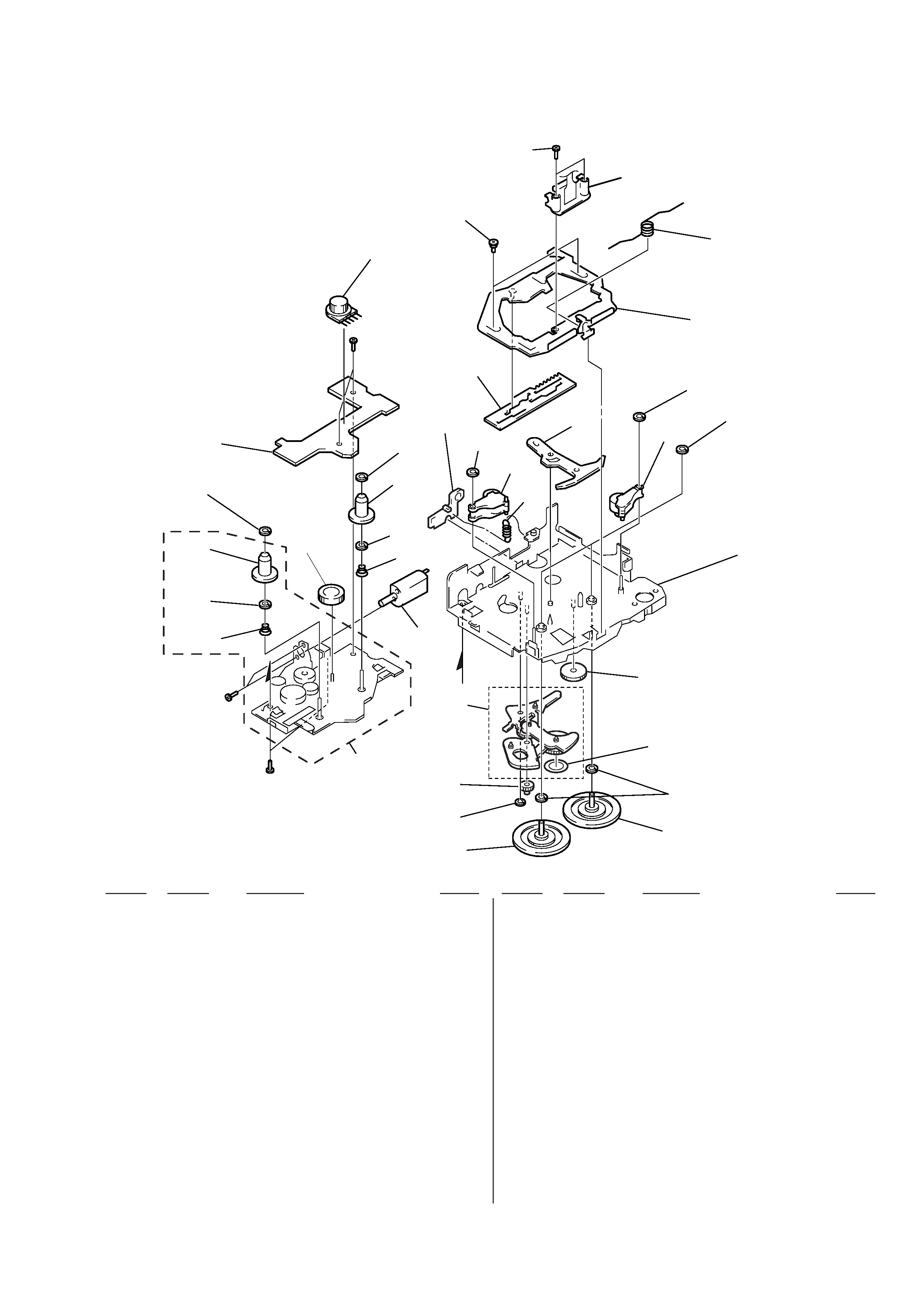
(4) MECHANISM DECK SECTION-2
(MG-52A-135)
151
X-3371-710-1 CHASSIS (S) ASSY
152
3-933-337-01 SPRING (B-T-R), CONE COIL
153
3-701-437-01 POLY-SLIDER (A)
154
3-933-333-01 GEAR (LDG-E)
155
3-933-339-01 SPRING (B-T-F), CONE COIL
156
3-933-345-01 GEAR, REEL
157
3-954-807-01 WASHER
158
1-660-169-21 REEL BOARD
159
3-341-752-11 WASHER, POLYETHYLENE
160
3-933-336-01 SPRING (ARM HANGER), TENSION
161
3-928-669-01 LEVER (PINCH SELECTION)
162
3-928-668-01 LEVER (MODE)
163
3-933-338-01 SCREW (HP), STEP
164
3-927-100-01 SCREW (+PS 2X10), SPECIAL
165
3-928-670-01 SPRING (PINCH PRESS)
* 166
X-3371-712-1 PLATE SUB ASSY, HEAD
Ref. No.
Part No.
Description
Remark
Ref. No.
Part No.
Description
Remark
167
3-364-151-01 WASHER
* 168
X-3371-701-1 CHASSIS (M) SUB ASSY (A)
169
X-3371-707-1 CLUTCH (PLAY) ASSY
170
3-701-437-21 WASHER
171
3-930-932-01 FLYWHEEL (F) (SEF)
172
A-3291-667-A CLUTCH (FR) ASSY
173
3-321-813-01 WASHER, COTTER POLYETHYLENE
174
3-933-343-01 GEAR (REVERSE)
175
3-933-383-01 SEAL (32), REFLECTION
176
X-3371-703-1 LEVER (GEAR) ASSY
177
X-3371-713-2 LEVER (PINCH) ASSY
178
X-3371-706-2 ARM (HANGER) ASSY
HP901
1-500-157-21 HEAD, MAGNETIC (PLAYBACK)
M902
A-3291-664-A MOTOR ASSY, SUB
(LOADING/TAPE OPERATION)
S901
1-692-885-11 SWITCH, ROTARY SLIDE (TAPE OPERATION)
169
175
170
171
172
173
174
176
164
163
165
166
159
167
177
168
162
S901
HP901
151
152
153
156
157
158
157
156
153
154
#6
M902
#6
#8
178
159
177
160
161
B
155