SERVICE MANUAL
FM/AM (MW/LW) CASSETTE CAR STEREO
US Model
Canadian Model
XR-M550
AEP Model
UK Model
XR-M500R
SPECIFICATIONS
XR-M500R/M550
Photo: XR-M550
Model Name Using Similar Mechanism
NEW
Tape Transport Mechanism Type
MG-25E-136
Dolby noise reduction manufactured under license from
Dolby Laboratories Licensing Corporation.
"DOLBY" and the double-D symbol ; are trademarks
of Dolby Laboratories Licencing Corporation.
Continued on next page
Cassette player section
Other specifications
AUDIO POWER SPECIFICATIONS (US model)
POWER OUTPUT AND TOTAL HARMONIC DISTORTION
19 watts per channel minimum continuous average power into
4 ohms, 4 channels driven from 20 Hz to 20 kHz with no more
than 1% total harmonic distortion.
Tape track
4-track 2-channel stereo
Wow and flutter
0.08 % (WRMS)
Frequency response
30 20,000 Hz
Signal-to-noise ratio
Tuner section
FM
Tuning range
87.5 108.0 MHz (XR-M500R)
Antenna terminal
External antenna connector
Intermediate frequency
10.7 MHz/450kHz
Usable sensitivity
8 dBf
Selectivity
75 dB at 400 kHz
Signal-to-noise ratio
66 dB (stereo),
72 dB (mono)
Harmonic distortion at 1 kHz
0.6 % (stereo),
0.3 % (mono)
Separation
35 dB at 1 kHz
Frequency response
30 15,000 Hz
MW/LW (XR-M500R)
Tuning range
MW: 531 1,602 kHz
LW: 153 279 kHz
Aerial terminal
External aerial connector
Intermediate frequency
10.7 MHz/450 kHz
Sensitivity
MW: 30
µV
LW: 40
µV
AM (XR-M550)
Tuning range
530 1,710 kHz
Antenna terminal
External antenna connector
Intermediate frequency
10.7 MHz/450 kHz
Sensitivity
30
µV
Dolby NR off
61 dB
58 dB
Dolby B NR
67 dB
64 dB
Cassettetype
TYPE II,
TYPE I
IV
87.5 107.9 MHz (XR-M550)
Ver 1.1 2002.09
9-870-088-13
Sony Corporation
2002I0500-1
e Vehicle Company
C
2002.09
Published by Sony Engineering Corporation

2
TABLE OF CONTENTS
1.
SERVICING NOTES ............................................... 3
2.
GENERAL
Location of Controls (XR-M500R) ................................
4
Setting the Clock .............................................................
4
Changing the Sound and Display Setting .......................
4
Locations of Controls (XR-M550) .................................
5
Setting the Clock .............................................................
5
Changing the Sound and Display Setting .......................
5
Installation (XR-M500R) ................................................
6
Installation (XR-M550) ..................................................
7
Connections (XR-M500R) ..............................................
8
Connections (XR-M550) ................................................ 12
3.
DISASSEMBLY ......................................................... 15
4.
ASSEMBLY ................................................................. 19
5.
MECHANICAL ADJUSTMENTS ....................... 24
6.
ELECTRICAL ADJUSTMENTS
Tape Deck Section .......................................................... 24
Tuner Section .................................................................. 25
7.
DIAGRAMS
7-1. Block Diagram TUNER/TAPE Section .................. 27
7-2. Block Diagram MAIN Section ................................ 28
7-3. Block Diagram
DISPLAY/BUS CONTROL Section ....................... 29
7-4. Block Diagram POWER SUPPLY Section ............. 30
7-5. Note for Printed Wiring Boards and
Schematic Diagrams ....................................................... 31
7-6. Printed Wiring Board
MAIN Board (Component Side) .............................. 32
7-7. Printed Wiring Board
MAIN Board (Conductor Side) ................................ 33
7-8. Schematic Diagram MAIN Board (1/4) .................. 34
7-9. Schematic Diagram MAIN Board (2/4) .................. 35
7-10. Schematic Diagram MAIN Board (3/4) .................. 36
7-11. Schematic Diagram MAIN Board (4/4) .................. 37
7-12. Printed Wiring Board SUB Board ............................ 38
7-13. Schematic Diagram SUB Board .............................. 39
7-14. Printed Wiring Board DISPLAY Board .................. 40
7-15. Schematic Diagram DISPLAY Board ..................... 41
7-16. IC Pin Function Description ........................................... 44
8.
EXPLODED VIEWS ................................................ 51
9.
ELECTRICAL PARTS LIST ............................... 55
Flexible Circuit Board Repairing
· Keep the temperature of the soldering iron around 270 °C dur-
ing repairing.
· Do not touch the soldering iron on the same conductor of the
circuit board (within 3 times).
· Be careful not to apply force on the conductor when soldering
or unsoldering.
Notes on chip component replacement
· Never reuse a disconnected chip component.
· Notice that the minus side of a tantalum capacitor may be dam-
aged by heat.
General
Outputs
Audio output (2) (M500R)
Audio output (3) (M550)
Power aerial relay control
lead
Power amplifier control
lead
Inputs
Telephone ATT control
lead
Illumination control lead
Tone controls
Bass
±9 dB at 100 Hz
Treble
±9 dB at 10 kHz
Power requirements
12 V DC car battery
(negative earth)
Dimensions
Approx. 178
(7 1/8
× 2 × 7 4/1 in.)
(7 1/4
× 2 1/8 × 6 1/2 in.)
× 50 × 182 mm
(w/h/d)
Mounting dimensions
Approx. 182
× 53 × 163 mm
(w/h/d)
Mass
Approx. 1.3 kg (2lb. 14 oz.)
Supplied accessories
Card remote commander
RM-X94 (XR-M550)
RM-X96 (XR-M500R)
Parts for installation and
connections (1 set)
Design and specifications are subject to change
without notice.
Power amplifier section
Outputs
Speaker outputs
Speaker impedance
4 8 ohms
Maximum power output 50 W
× 4 (at 4 ohms)
3
SECTION 1
SERVICING NOTES
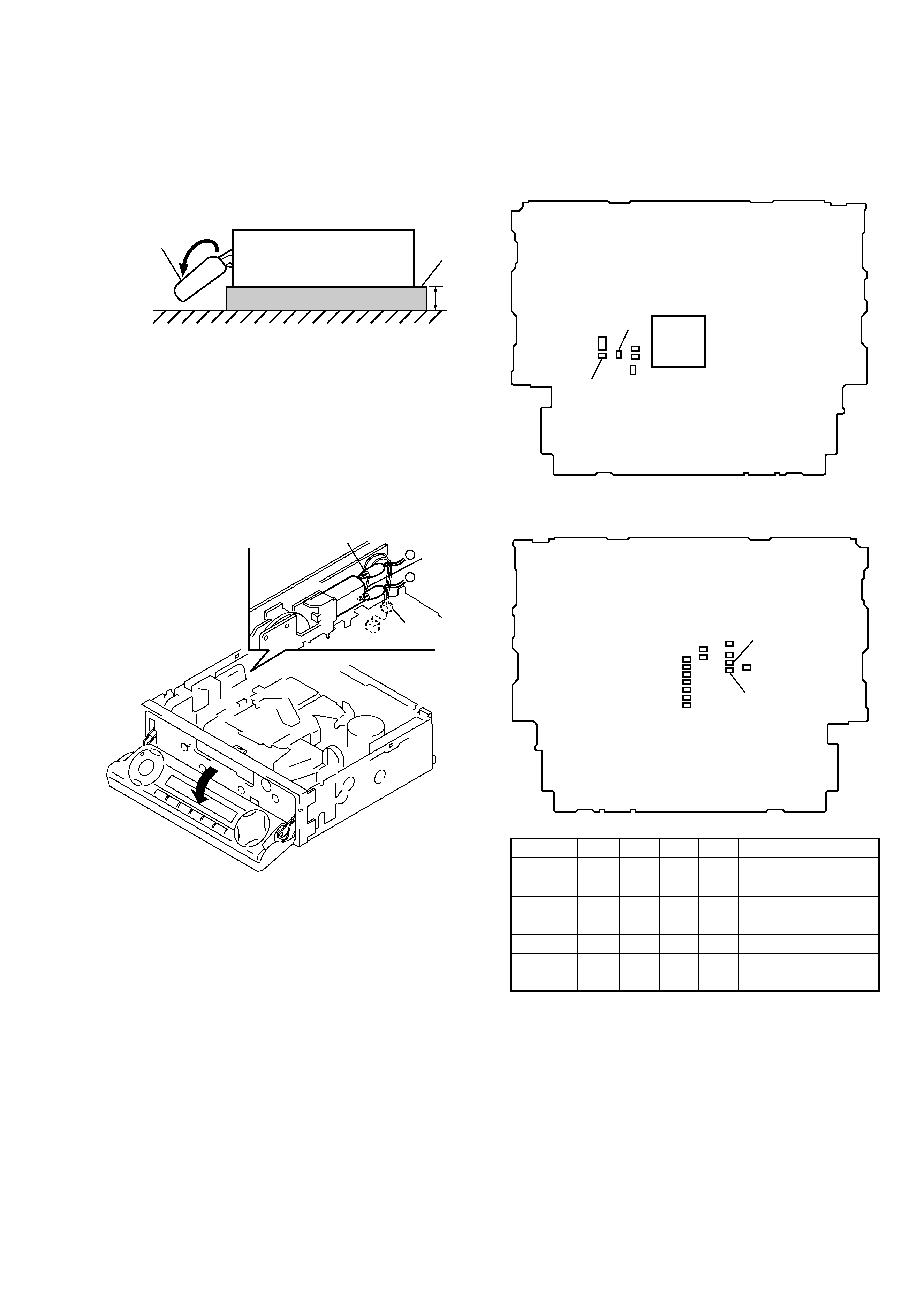
PRECAUTION ON OPEN/CLOSE FRONT PANEL
The front panel opens to the bottom of main unit.
In performing the repair, place the main unit on the base having
the height exceeding 1 cm.
Open the front panel by supplying the power through the follow-
ing steps:
1. Disconnect the motor connector (CN501) from main board.
2. Supply the power to the motor.
Voltage
: 9 V
Violet wiring : MOTOR
Gray wiring
: MOTOR +
front panel
XR-M500R/M550
( SIDE VIEW)
1cm
base
gray wiring
violet
wiring
connector
(CN501)
+
MODEL IDENTIFICATION
There are four types of main board in according of destination for
XR-M500R.
MAIN BOARD (Componet Side)
R625
R626
R719
R720
IC601
MAIN BOARD (Conductor Side)
R625 R626 R719 R720
Indicated language
TYPE A
aa
××
English, Spanish,
Swedish, Portuguese
TYPE B
××
aa
German, Italian, Dutch,
French
TYPE C
×
aa
×
English, German
TYPE D
a
××
a
English, Polish, Czeck,
Turkish
TYPE A, B, C, or D can also be identified from the front panel
display language.
For a switching method of display language, see page 4.
4
SECTION 2
GENERAL
This section is extracted from
instruction manual.
6
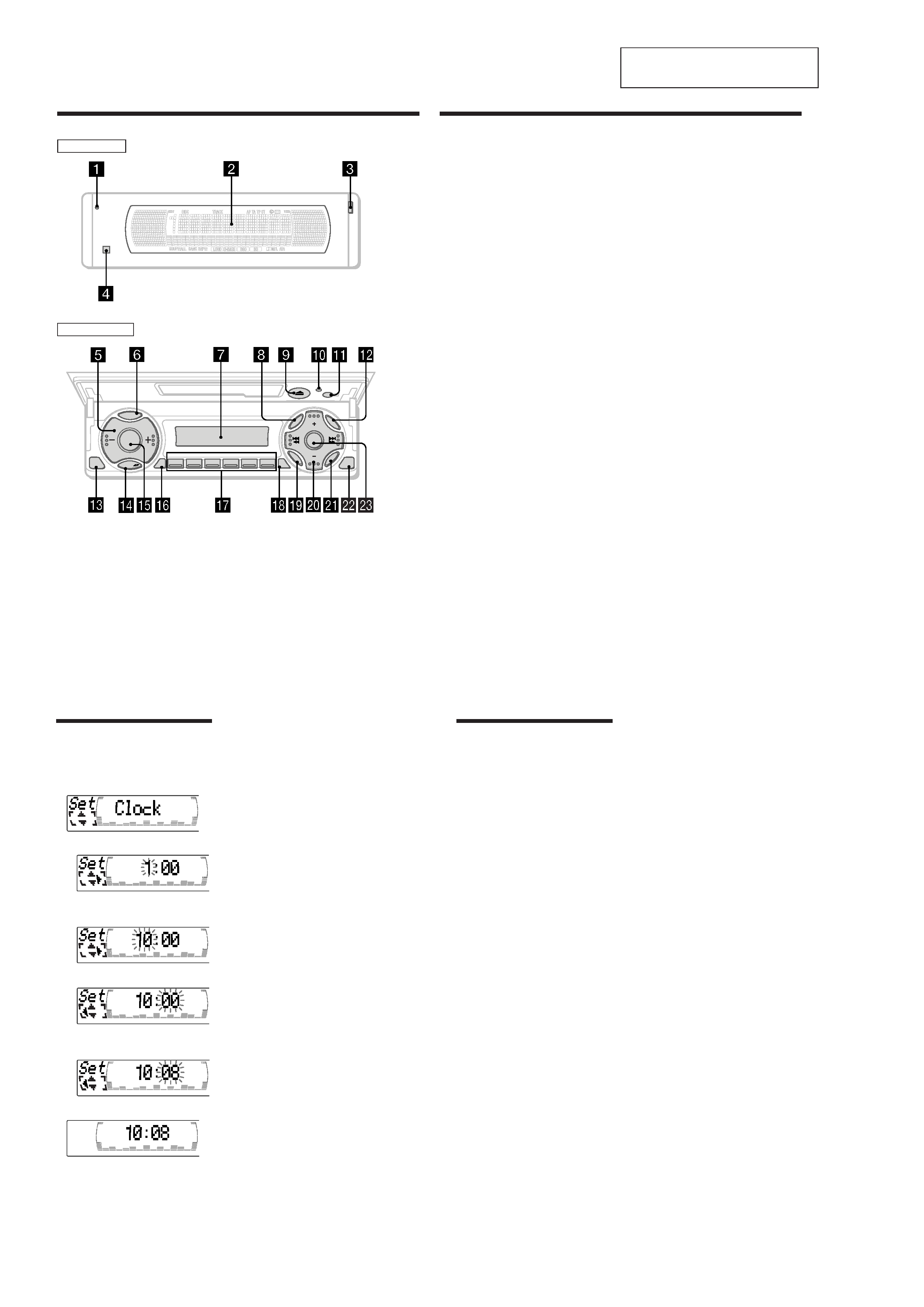
Location of controls
SOURCE
123
456
CLOSE
OFF
DISC
DISC
EN
TE
R
SOUND
M
EN
U
LIST
REP
SHUF
DSPL
PTY
MODE
XR-M500R
TA
AF
D-BASS
Security side
Operation side
7
qk TA button 16, 17, 18
ql SOUND button
w; PRST/DISC+/ (cursorup/down) buttons
SEEK/AMS/+ (cursorleft/right) buttons
13
wa ENTER button
ws CLOSE button
wd D-BASSbutton
* Warning when installing in a car
without ACC (accessory) position on
the ignition key switch
Be sure to press(OFF) on the unit for
two seconds to turn off the clock display
after turning off the engine.
When you press (OFF) only momentarily,
the clock display does not turn off and this
causes battery wear.
The corresponding buttons of the unit
control the same functions as those on
the card remote commander.
10 Reset button 8
2 Main display window
3 OPENbutton 38
4qa Receptor for the card remote
commander
5 Volume adjust buttons
6 DSPL/PTY (display mode change/
programme type) button
7 Sub display window
8 MENU button
9 Z (eject) button 11
qs LISTbutton
qd OFF button* 9
qf MODE button
qg SOURCE(TUNER/TAPE/CD/MD) button
qh AF button 16, 18
qj Number buttons
During radio reception:
Preset number select
13, 14, 17, 33, 34
During tape playback:
(1) REP 12
During CD/MD playback:
(1) REP 28
(2) SHUF 28
10
Tips
· You can use the convenient CT function to set
the clock automatically (page 20).
· When the D.Info mode is set to "on," the time is
always displayed (except for some functions of
SA mode) (page 23).
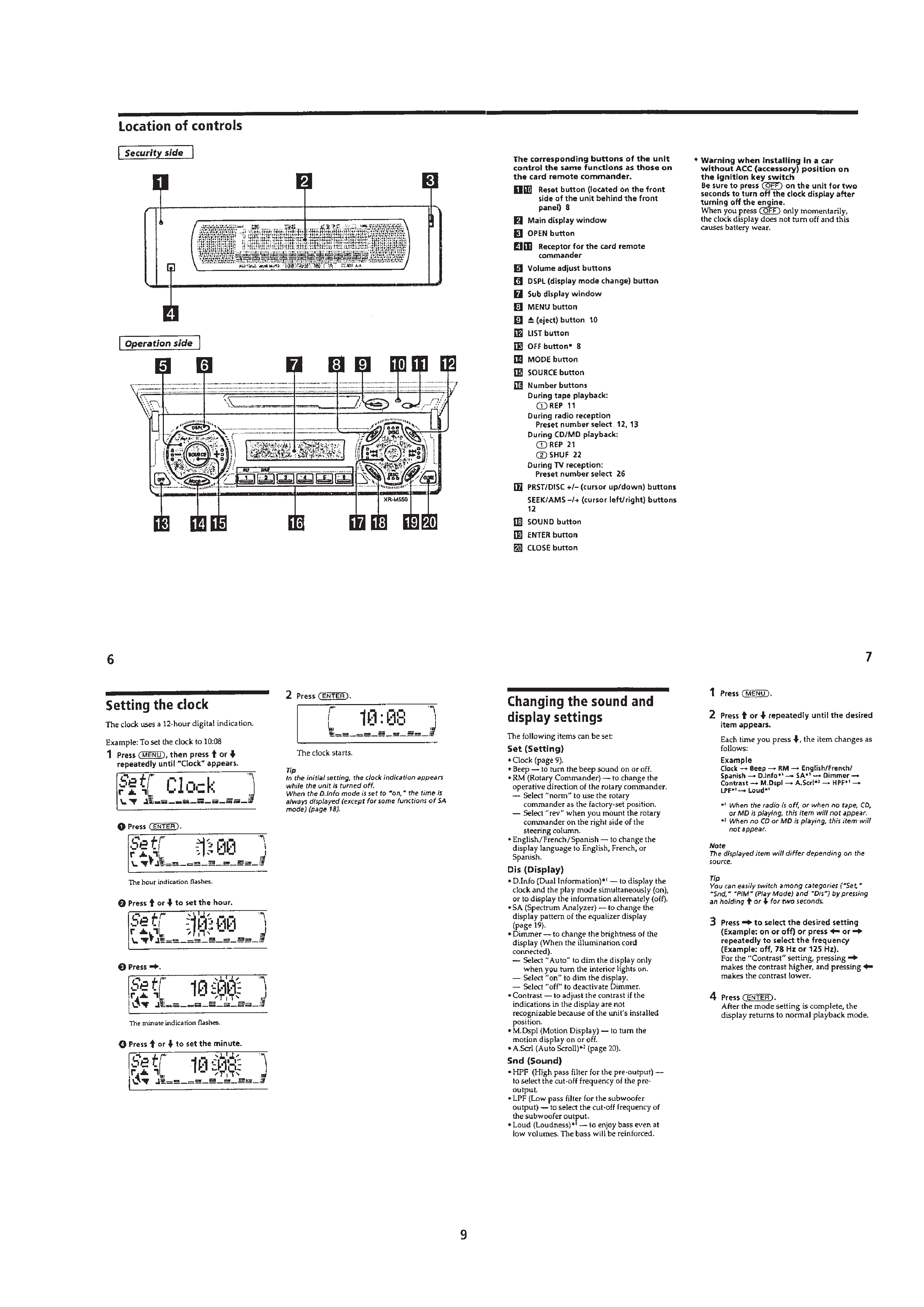
Setting the clock
The clock uses a 24-hour digital indication.
Example: To set the clock to 10:08
1 Press(MENU), then M or m repeatedly
until "Clock"appears.
1
Press(ENTER).
The hour indication flashes.
2
PressM or m to set the hour.
3
Press,.
The minute indication flashes.
4
PressM or m to set the minute.
2 Press(ENTER).
The clock starts.
23
Changing the sound and
display settings
The following items can be set:
Set (Setting)
·Clock (page 10).
·CT (Clock Time) (page 20).
·Beep -- to turn the beep sound on or off.
·RM (Rotary Commander) -- to change the
operative direction of the rotary commander.
-- Select "norm" to use the rotary
commander as the factory-set position.
-- Select "rev" when you mount the rotary
commander on the right side of the
steering column.
·English/Spanish/Portuguese/Swedish -- to
change the display language to English,
Spanish, Portuguese or Swedish.
Dis (Display)
·D.Info (Dual Information) -- to display the
clock and the play mode simultaneously (on),
or to display the information alternately (off).
·SA (Spectrum Analyzer) -- to change the
display pattern of the equalizer display
(page 25).
·Dimmer -- to change the brightness of the
display (When the Illumination terminal
connected).
-- Select "on" to dim the display.
-- Select "off" to deactivate Dimmer.
·Contrast -- to adjust the contrast if the
indications in the display are not
recognisable because of the unit's installed
position.
·M.Dspl (Motion Display) -- to turn the
motion display on or off.
·A.Scrl (Auto Scroll) (page 27).
continue to next page t
24
1 Press(MENU).
2 PressM or m repeatedly until the desired
item appears.
Each time you press m, the item changes as
follows:
Example
Clockt CT t Beep t RM t English/
Spanish/Portuguese/Swedisht D.Info t SA
t Dimmer t Contrast t M.Dspl*1 t A.Scrl*2
*1 When no CD or MD is playing, this item will
not appear.
*2 When the radio is off, or when no tape, CD,
or MD is playing, this item will not appear.
Note
The displayed item will differ depending on the
source.
Tip
You can easily switch among categories ("Set,"
"Snd" (Sound), "P/M" (Play Mode) and "Dis") by
pressing M or m for two seconds.
3 Press, to selectthe desired setting
(Example: on or off).
4 Press(ENTER).
After the mode setting is complete, the
display returns to normal playback mode.
(XR-M500R)
5
(XR-M550)