SERVICE MANUAL
Model Name Using Similar Mechanism
XR-4300R
Tape Transport Mechanism Type
MG-25G-136
FM/MW/LW CASSETTE CAR STEREO
AEP Model
UK Model
SPECIFICATIONS
XR-L500/L500V/L500X
Photo: XR-L500
Ver 1.1 2001.05
9-870-247-12
Sony Corporation
2001E0500-1
e Vehicle Company
C
2001.5
Shinagawa Tec Service Manual Production Group
Cassette Player section
Tape track
4-track 2-channel stereo
Wow and flutter
0.08 % (WRMS)
Frequency response
30 18,000 Hz
Signal-to-noise ratio
Tuner section
FM
Tuning range
87.5 108.0 MHz
Aerial terminal
External aerial connector
Intermediate frequency
10.7 MHz/450 kHz
Usable sensitivity
8 dBf
Selectivity
75 dB at 400 kHz
Signal-to-noise ratio
66 dB (stereo),
72 dB (mono)
Harmonic distortion at 1 kHz
0.6 % (stereo),
0.3 % (mono)
Separation
35 dB at 1 kHz
Frequency response
30 15,000 Hz
MW/LW
Tuning range
MW: 531 1,602 kHz
LW: 153 279 kHz
Aerial terminal
External aerial connector
Intermediate frequency
10.7 MHz/450 kHz
Sensitivity
MW: 30
µV
LW: 40
µV
Power amplifier section
Outputs
Speaker outputs
(sure seal connectors)
Speaker impedance
4 8 ohms
Maximum power output
50 W
× 4 (at 4 ohms)
General
Outputs
Audio outputs (Rear)
Power aerial relay control
lead
Power amplifier control lead
Inputs
Telephone ATT control lead
Remote controller input
connector
Aerial input connector
Tone controls
Bass
±8 dB at 100 Hz
Treble
±8 dB at 10 kHz
Loudness
100 Hz +8 dB
10 kHz +2 dB
Power requirements
12 V DC car battery
(negative earth)
Dimensions
Approx. 178
× 50 × 176
mm (w/h/d)
Mounting dimensions
Approx. 182
× 53 × 161
mm (w/h/d)
Mass
Approx. 1.2 kg
Supplied accessories
Parts for installation and
connections (1 set)
Front panel case (1)
Note
This unit cannot be connected to a digital preamplifier
or an equalizer.
Design and specifications are subject to change
without notice.
Cassette type
TYPE II, IV
61 dB
TYPE I
58 dB

2
XR-L500/L500V/L500X
TABLE OF CONTENTS
1.
GENERAL
Location of Controls .......................................................
3
Setting the Clock .............................................................
4
2.
DISASSEMBLY
2-1. Disassembly Flow ...........................................................
8
2-2. Mechanism Deck (MG-25G-136) ...................................
8
2-3. MAIN Board ...................................................................
9
2-4. Heat Sink (ISO2P) ..........................................................
9
3.
ASSEMBLY OF MECHANISM DECK
3-1. Housing ........................................................................... 10
3-2. Arm (Suction) ................................................................. 10
3-3. Lever (LDG-A)/(LDG-B) ............................................... 11
3-4. Gear (LDG-FT) ............................................................... 11
3-5. Guide (C) ......................................................................... 12
3-6. Mounting Position of Capstan/reel Motor (M901) ........ 12
4.
MECHANICAL ADJUSTMENTS ....................... 13
5.
ELECTRICAL ADJUSTMENTS
Tape Deck Section .......................................................... 13
Tuner Section .................................................................. 13
6.
DIAGRAMS
6-1. Note for Printed Wiring Boards and
Schematic Diagrams ....................................................... 14
6-2. Printed Wiring Board MAIN Board ......................... 15
6-3. Schematic Diagram MAIN Board (1/3) ................... 16
6-4. Schematic Diagram MAIN Board (2/3) ................... 17
6-5. Schematic Diagram MAIN Board (3/3) ................... 18
6-6. Printed Wiring Board SUB Board ............................ 19
6-7. Schematic Diagram SUB Board ............................... 19
6-8. Printed Wiring Board
KEY Board (XR-L500/L500X) ................................ 20
6-9. Printed Wiring Board KEY Board (XR-L500V) ..... 21
6-10. Schematic Diagram KEY Board .............................. 22
6-11. IC Pin Function Description ........................................... 26
7.
EXPLODED VIEWS
7-1. General Section ............................................................... 29
7-2. Front Panel Section ......................................................... 30
7-3. Mechanism Deck Section (MG-25G-136) ..................... 31
8.
ELECTRICAL PARTS LIST ............................... 32
Notes on chip component replacement
· Never reuse a disconnected chip component.
· Notice that the minus side of a tantalum capacitor may be dam-
aged by heat.
Flexible Circuit Board Repairing
· Keep the temperature of the soldering iron around 270 °C dur-
ing repairing.
· Do not touch the soldering iron on the same conductor of the
circuit board (within 3 times).
· Be careful not to apply force on the conductor when soldering
or unsoldering.
3
XR-L500/L500V/L500X
SECTION 1
GENERAL
This section is extracted from
instruction manual.
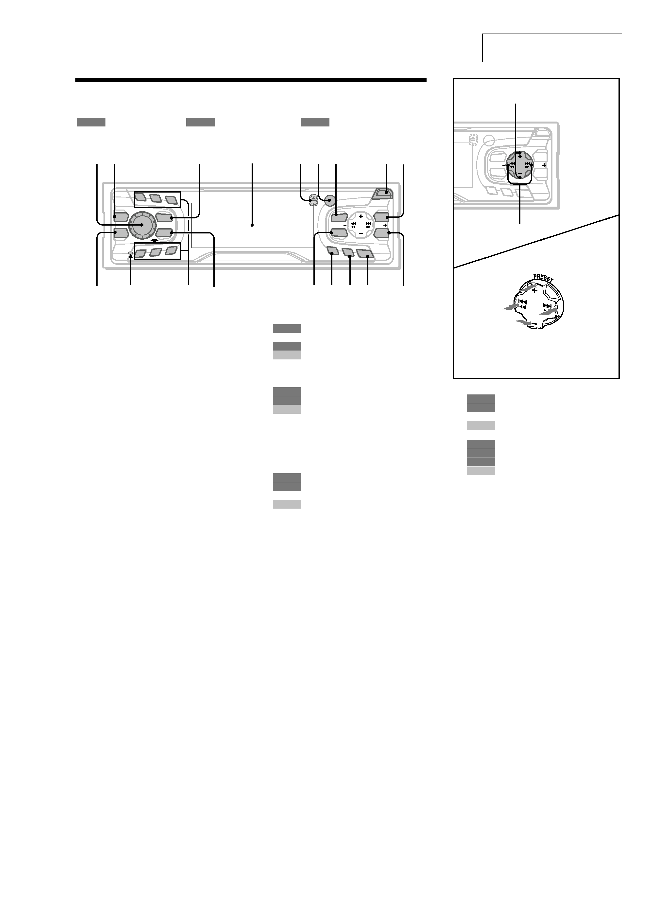
Location of controls
Refer to the pages listed for details.
: During tape playback
: During radio reception
: During menu mode
a Volume control dial 13
b MBP button 19
c SOURCE (Power on/Tape/Radio) button
5, 9, 10, 11, 13, 19, 20, 22
d Display window
e Z (eject) button (located on the front side
of the unit, behind the front panel) 9
f Receptor for the card remote
commander
g MENU button 8, 9, 10, 14, 15, 18, 19,
h OPEN button 7, 9
i
20, 22, 23, 24
PTY/DSPL button 12, 15
j EQ7 button 19
k RESET button (located on the front side of
the unit, behind the front panel) 7
l Number buttons
(3) REP 9
10, 11, 13, 14
(3) REP 21
(6) SHUF 21
m MODE (o) button
9
10, 11, 13
20, 22
n SOUND button 17, 19
o AF button 12, 14
p TA button 13, 14
q OFF (Stop/Power off) button*1 5, 7, 9,
20
r ENTER button
11, 14
8, 9, 10, 15, 18, 19, 20, 22, 23,
24
22, 23
*1 Warning when installing in a car without
an ACC (accessory) position on the
ignition switch
After turning off the ignition, be sure to press
(OFF) on the unit for 2 seconds to turn off
the clock display.
Otherwise, the clock display does not turn off
and this causes battery drain.
TAPE
RADIO
MENU
1
2
3
4
5
6
AF
TA
OFF
MENU
PTY
SOUND
ENTER
MBP
SOURCE
REP
MODE
EQ 7
PRES ET
SEEK
SEEK
OPEN
TAPE
RADIO
CD/MD
TAPE
RADIO
CD/MD
RADIO
MENU
CD/MD
12
3
4
567
89
0
qa
qs qd
qfqgqhqj
qk
s PRESET buttons (+/)
10, 11, 15
8, 9, 10, 14, 15, 18, 19, 20, 22,
23, 24
20, 22, 23
t SEEK buttons (/+)
9
10, 11, 13
8, 9, 15, 17, 18, 19, 20, 24
20, 22, 23
AF
TA
OFF
MENU
SOUND
ENTER
PR
ESET
SEEK
SEEK
OPEN
PTY
(SEEK)
(): to select
leftwards/
.
(SEEK)
(+): to select
rightwards/
>
(PRESET)
(+): to select upwards
In menu mode, the currently selectable button (s)
of these four are indicated with a " M" in the display.
(PRESET)
(): to select downwards
RADIO
MENU
CD/MD
TAPE
RADIO
MENU
CD/MD
ql
w;
4
XR-L500/L500V/L500X
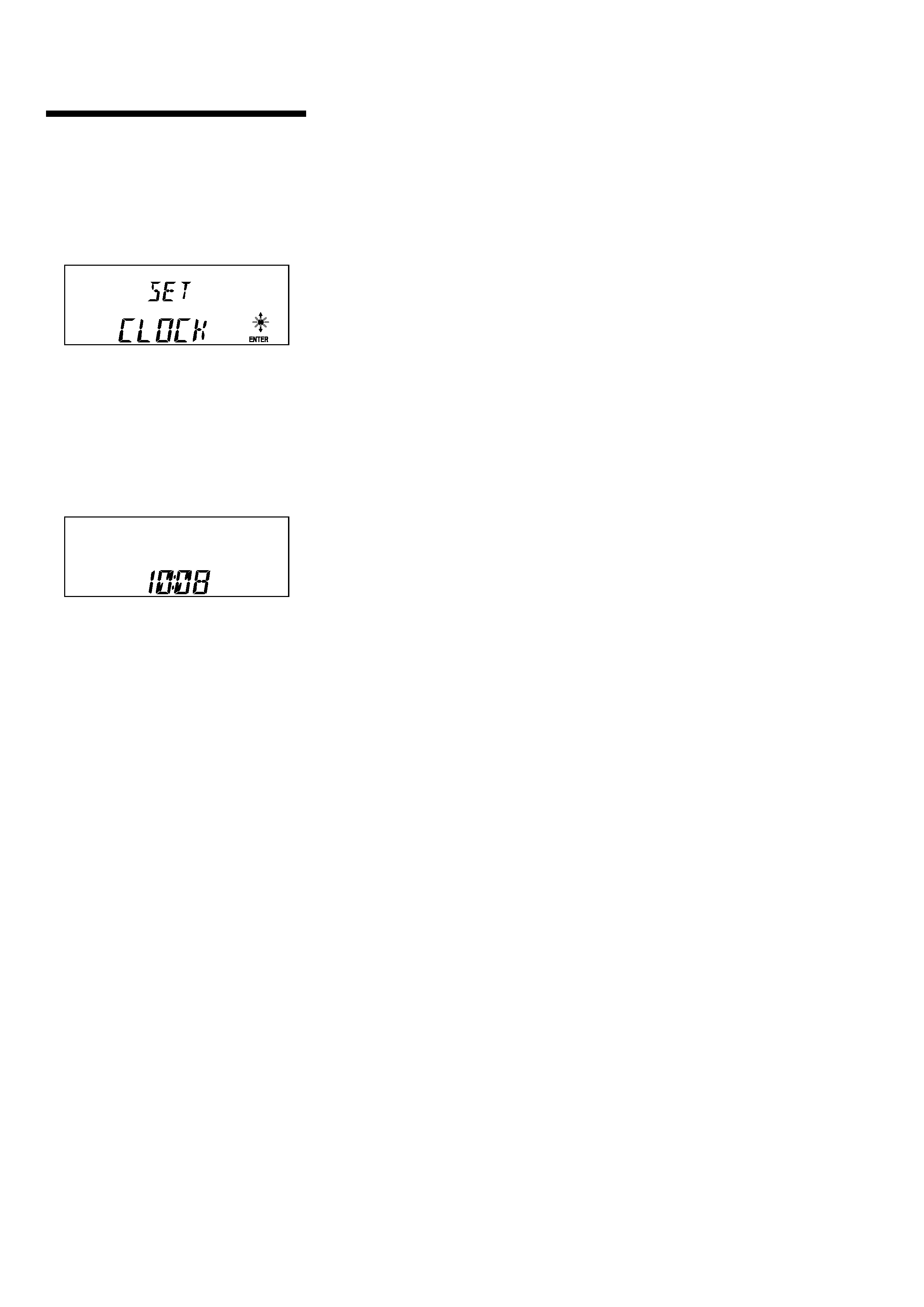
Setting the clock
The clock uses a 24-hour digital indication.
Example: To set the clock to 10:08
1 Press (MENU), then press either side
of (DISC/PRESET) or (PRESET)
repeatedly until "CLOCK" appears.
1
Press (ENTER).
The hour indication flashes.
2
Press either side of (DISC/PRESET)
or (PRESET) to set the hour.
3
Press the (+) side of (SEEK).
The minute indication flashes.
4
Press either side of (DISC/PRESET)
or (PRESET) to set the minute.
2 Press (ENTER).
The clock starts. After the clock setting is
completed, the display returns to normal play
mode.
Tips
· You can set the clock automatically with the RDS
feature (page 15).
· When D.INFO mode is set to ON, the time is always
displayed (page 18).
5
XR-L500/L500V/L500X
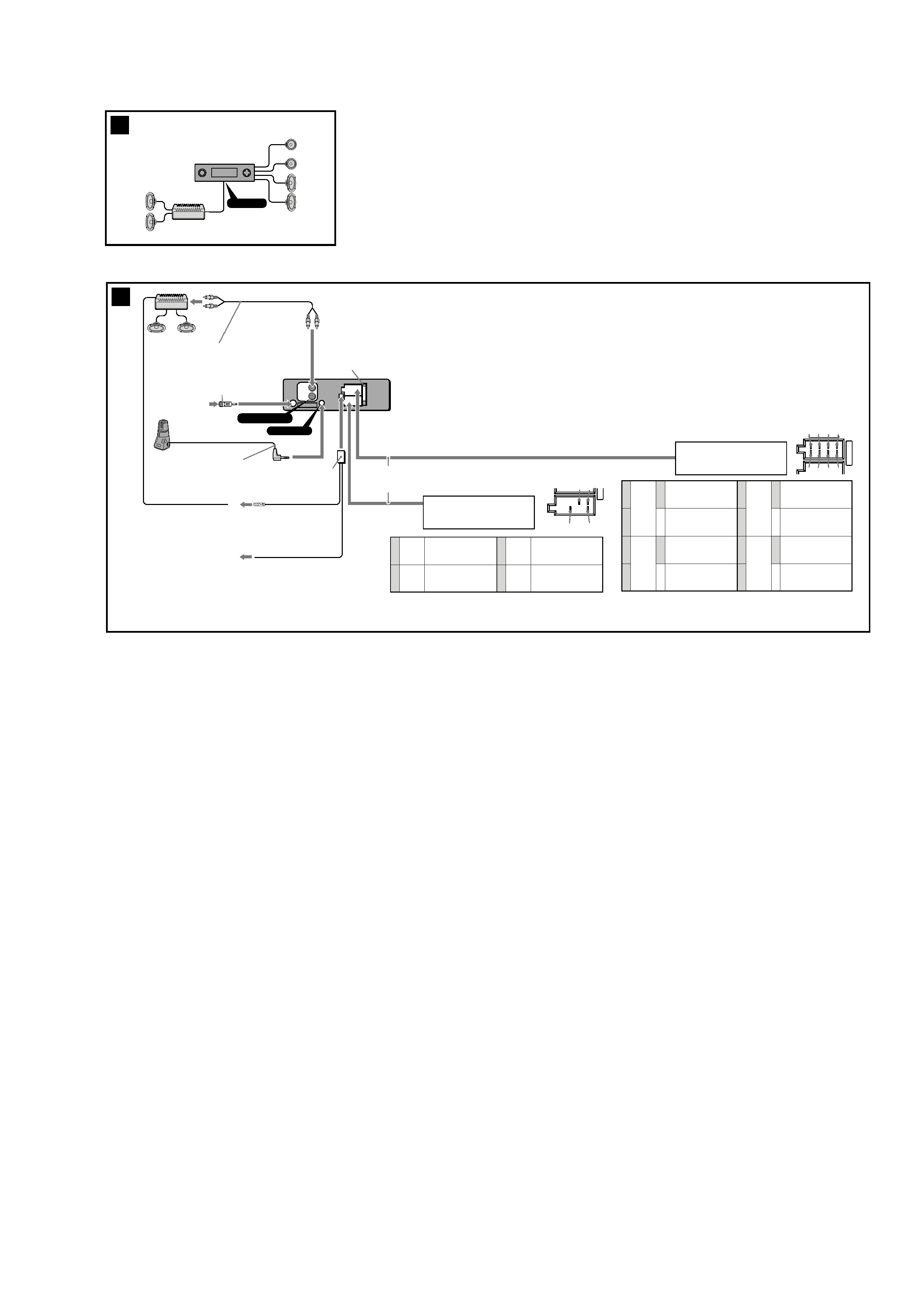
AUDIO OUT
REAR
BUS AUDIO
IN
3
7
from car aerial
*
von Autoantenne
*
de l'antenne de la voiture
*
dall'antenna dell'auto
*
van een auto-antenne
*
Fuse (10 A)
Sicherung (10 A)
Fusible (10 A)
Fusibile (10 A)
Zekering (10 A)
8
AUDIO OUT REAR
REMOTE IN
AMP REM
Max. supply current 0.3 A
max. Versorgungsstrom 0,3 A
Courant max. fourni 0,3 A
Alimentazione massima fornita 0,3 A
Max. voedingsstroom 0,3 A
Light blue
Hellblau
Bleu ciel
Azzurro
Hemelsblauw
Blue/white striped
Blau-weiß gestreift
Rayé bleu/blanc
A strisce blu e bianche
Blauw/wit gestreept
ATT
B
from the car's speaker connector
vom Lautsprecheranschluß des Fahrzeugs
du connecteur de haut-parleur de la voiture
dal connettore del diffusore dell'auto
van de autoluidsprekerstekker
13 5 7
24
6 8
* Note for the aerial connecting
If your car aerial is an ISO (International
Organisation for Standardisation) type, use
the supplied adaptor 7 to connect it.
First connect the car aerial to the supplied
adaptor, then connect it to the aerial jack
of the master unit.
* Hinweis zum Anschließen der Antenne
Wenn Ihre Fahrzeugantenne der ISO-Norm
(ISO = International Organization for
Standardization - Internationale
Normungsgemeinschaft) entspricht, schließen
Sie sie mit Hilfe des mitgelieferten Adapters 7
an.
Verbinden Sie zuerst die Fahrzeugantenne mit
dem mitgelieferten Adapter, und verbinden
Sie diesen dann mit der Antennenbuchse des
Hauptgeräts.
* Remarque sur le raccordement de
l'antenne
Si votre antenne de voiture est de type
ISO (organisation internationale de
normalisation), utilisez l'adaptateur
fourni 7 pour la raccorder.
Raccordez d'abord l'antenne de voiture à
l'adaptateur fourni et, ensuite, à la prise
d'antenne de l'appareil principal.
RCA pin cord (not supplied)
Cinchkabel (nicht mitgeliefert)
Cordon à broche RCA (non fourni)
Cavo a piedini RCA (non in dotazione)
Tulpstekkersnoer (niet bijgeleverd)
Insert with the cord upwards.
Mit dem Kabel nach oben einsetzen!
Insérez avec le câble vers le haut.
Inserire con il cavo rivolto verso l'alto.
Inbrengen met het snoer naar boven.
* Nota per il collegamento dell'antenna
Se la vostra antenna della macchina è di
tipo ISO (International Organization
Standardization), utilizzare l'adattatore
7
in dotazione per collegarla.
Collegare prima l'antenna della macchina
all'adattatore in dotazione, quindi
collegarla alla presa dell'antenna
dell'apparecchio principale.
* Opmerking bij de antenne-aansluiting
Indien uw wagen is uitgerust met een
antenne van het type ISO (International
Organisation for Standardization), moet
u die aansluiten met behulp van de
meegeleverde adaptor 7.
Sluit eerst de auto-antenne aan op de
meegeleverde adaptor en vervolgens de
antennestekker op het hoofdtoestel.
from the car's power connector
vom Stromanschluß des Fahrzeugs
du connecteur d'alimentation de la voiture
van de autovoedingsstekker
dal connettore di alimentazione dell'auto
57
48
Yellow
Gelb
Jaune
Giallo
Geel
Blue
Blau
Bleu
Blu
Blauw
continuous power supply
permanente Stromversorgung
alimentation continue
alimentazione continua
continu voeding
power aerial control
Motorantenne
antenne électrique
comando dell'antenna elettrica
automatische antenne
7
8
4
5
Red
Rot
Rouge
Rosso
Rood
Black
Schwarz
Noir
Nero
Zwart
switched power supply
geschaltete Stromversorgung
alimentation commutée
alimentazione commutata
geschakelde voeding
earth
Masse
masse
terra
aarding
Positions 1, 2, 3 and 6 do not have pins.
An Position 1, 2, 3 und 6 befinden sich keine Stifte.
Les positions 1, 2, 3 et 6 ne comportent pas de broches.
Le posizioni 1, 2, 3 e 6 non hanno piedini.
De posities 1, 2, 3 en 6 hebben geen pins.
A
Power connecting cord (supplied with only South European model)
Stromversorgungskabel
Cordon d'alimention
Cavo di alimentazione
Voedingskabel
Negative polarity positions 2, 4, 6, and 8 have striped cords.
An den negativ gepolten Positionen (2, 4, 6 und 8) befinden sich gestreifte Adern.
Les positions de polarité négative 2, 4, 6 et 8 sont dotées de cordons rayés.
Le posizioni a polarità negativa 2, 4, 6 e 8 hanno cavi rigati.
De negatieve posities 2, 4, 6 en 8 hebben gestreepte kabels.
1
2
3
4
Speaker, Rear, Right
Lautsprecher hinten rechts
haut-parleur, arrière, droit
Diffusore, posteriore, destro
Luidspreker, achter, rechts
Speaker, Rear, Right
Lautsprecher hinten rechts
haut-parleur, arrière, droit
Diffusore, posteriore, destro
Luidspreker, achter, rechts
Speaker, Front, Right
Lautsprecher vorne rechts
haut-parleur, avant, droit
Diffusore, anteriore, destro
Luidspreker, voor, rechts
Speaker, Front, Right
Lautsprecher vorne rechts
haut-parleur, avant, droit
Diffusore, anteriore, destro
Luidspreker, voor, rechts
5
6
7
8
Speaker, Front, Left
Lautsprecher vorne links
haut-parleur, avant, gauche
Diffusore, anteriore, sinistro
Luidspreker, voor, links
Speaker, Front, Left
Lautsprecher vorne links
haut-parleur, avant, gauche
Diffusore, anteriore, sinistro
Luidspreker, voor, links
Speaker, Rear, Left
Lautsprecher hinten links
haut-parleur, arrière, gauche
Diffusore, posteriore, sinistro
Luidspreker, achter, links
Speaker, Rear, Left
Lautsprecher hinten links
haut-parleur, arrière, gauche
Diffusore, posteriore, sinistro
Luidspreker, achter, links
Purple
Violett
Mauve
Viola
Paars
Green
Grün
Vert
Verde
Groen
White
Weiß
Blanc
Bianco
Wit
Grey
Grau
Gris
Grigio
Grijs
+
+
+
+
2
A
AUDIO OUT