1
Model Name Using Similar Mechanism
XR-H572A/H573A
Tape Transport Mechanism Type
MG-25H-136
SERVICE MANUAL
XR-H592WG/H593WG
FM/AM CASSETTE CAR STEREO
Notes on Chip Component Replacement
· Never reuse a disconnected chip component.
· Notice that the minus side of a tantalum capacitor may be
damaged by heat.
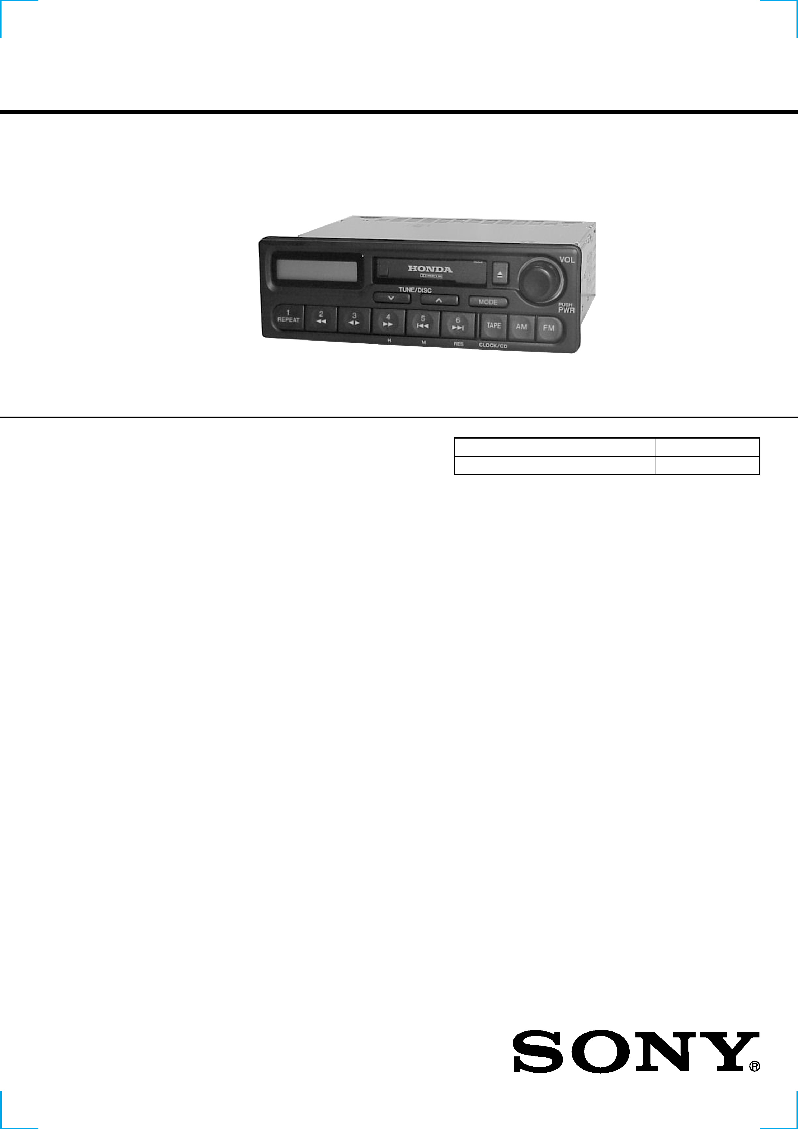
Photo: XR-H593WG
Dolby noise reduction manufactured under license from Dolby Labo-
ratories Licensing Corporation.
"DOLBY" and the double-D symbol ; are trademarks of Dolby
Laboratories Licensing Corporation.

2
TABLE OF CONTENTS
1. DISASSEMBLY
1-1. Cover .................................................................................. 3
1-2. Front Panel Assy ................................................................ 3
1-3. Mechanism Deck Block ..................................................... 4
1-4. Main Board ........................................................................ 4
2. ASSEMBLY OF MECHANISM DECK
2-1. Arm (Drive) Assy ............................................................... 5
2-2. Gear (LDG-D) .................................................................... 5
2-3. Gear (LDG-B) .................................................................... 6
2-4. Gear Position Setting ......................................................... 6
2-5. Chassis (S) Assy ................................................................. 7
2-6. Lever (Mode) ...................................................................... 7
2-7. Head Plate Assy ................................................................. 8
2-8. Lever (Pinch) Assy ............................................................. 8
2-9. Main Motor Assy ............................................................... 9
2-10. Flywheel (F) ....................................................................... 9
2-11. Belt (25) ........................................................................... 10
2-12. Hanger .............................................................................. 10
2-13. Housing ............................................................................ 11
2-14. Arm (Suction) Assy .......................................................... 11
2-15. Lever (LDG-A) ................................................................ 12
2-16. Lever (LDG-B) ................................................................. 12
2-17. Gear (Loading FT) ........................................................... 13
3. MECHANICAL ADJUSTMENTS ........................... 14
4. ELECTRICAL ADJUSTMENTS
Tape Section ......................................................................... 14
Tuner Section ........................................................................ 15
5. DIAGRAMS
5-1. Block Diagram Tape Section ....................................... 19
5-2. Block Diagram Tuner Section ...................................... 20
5-3. Block Diagram Control Section ................................... 21
5-4. Printed Wiring Boards Main Section ........................... 22
5-5. Schematic Diagram Main Section (1/3) ....................... 24
5-6. Schematic Diagram Main Section (2/3) ....................... 25
5-7. Schematic Diagram Main Section (3/3) ....................... 26
5-8. Schematic Diagram Display Section ............................ 27
5-9. Printed Wiring Boards Display Section ....................... 28
5-10. IC Pin Description ............................................................ 32
6. EXPLODED VIEWS
6-1. Chassis Section ................................................................ 34
6-2. Front Panel Section .......................................................... 35
6-3. Mechanism Deck Section (1) ........................................... 36
6-4. Mechanism Deck Section (2) ........................................... 37
6-5. Mechanism Deck Section (3) ........................................... 38
7. ELECTRICAL PARTS LIST ................................... 39
3
4
screw (TP)
3
screw (TP)
9
CN800
1
LAMP board
2
CN802
claws
(holder (B))
0
front panel assy
5
claws
6
claws
7
claws
8
claws
1
P 2.6x6
2
P 2.6x8
4
claws
3
claws
5
claws
6
cover
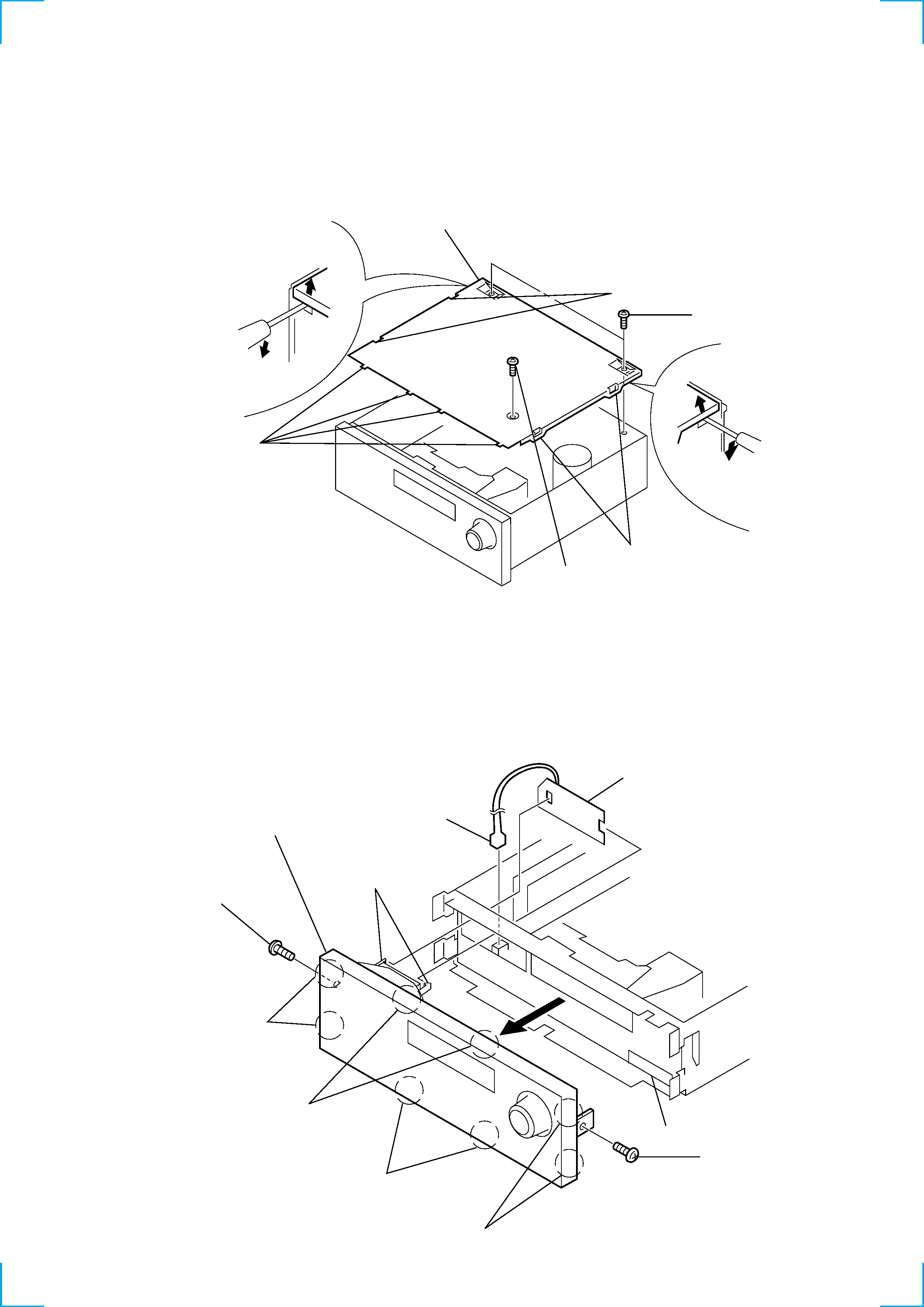
1-2. FRONT PANEL ASSY
Note : When removing the LAMP board from the holder (B), take
care not to bend or break the claw of the holder.
SECTION 1
DISASSEMBLY
Note : Follow the disassembly procedure in the numerical order given.
1-1. COVER
4
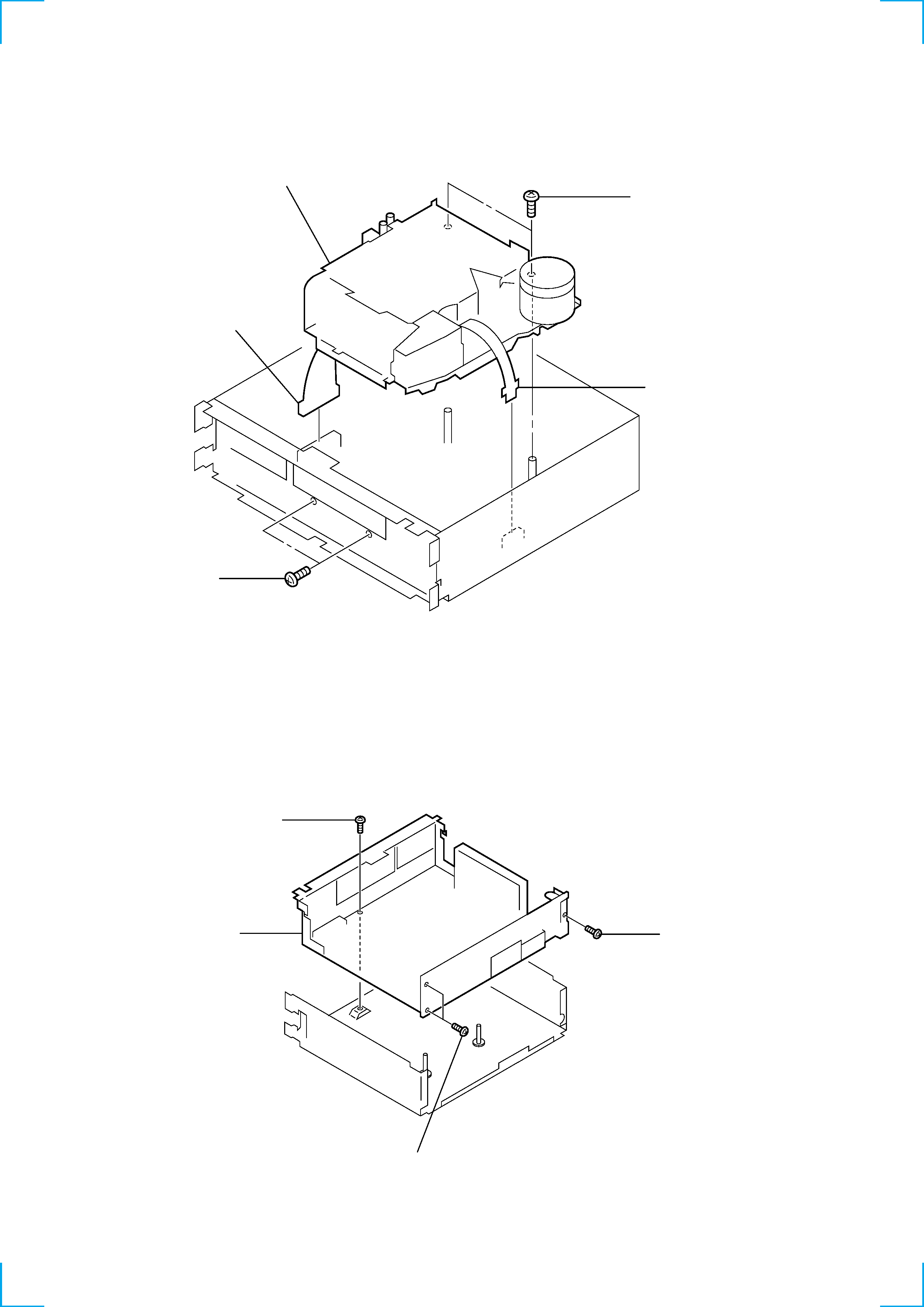
1-3. MECHANISM DECK BLOCK
1-4. MAIN BOARD
1
P 2.6x6
3
CNP401
1
P 2.6x6
5
mechanism deck block
4
CNP501
1
P 2.6x6
2
P 2.6x6
3
P 2.6x6
4
MAIN board
5
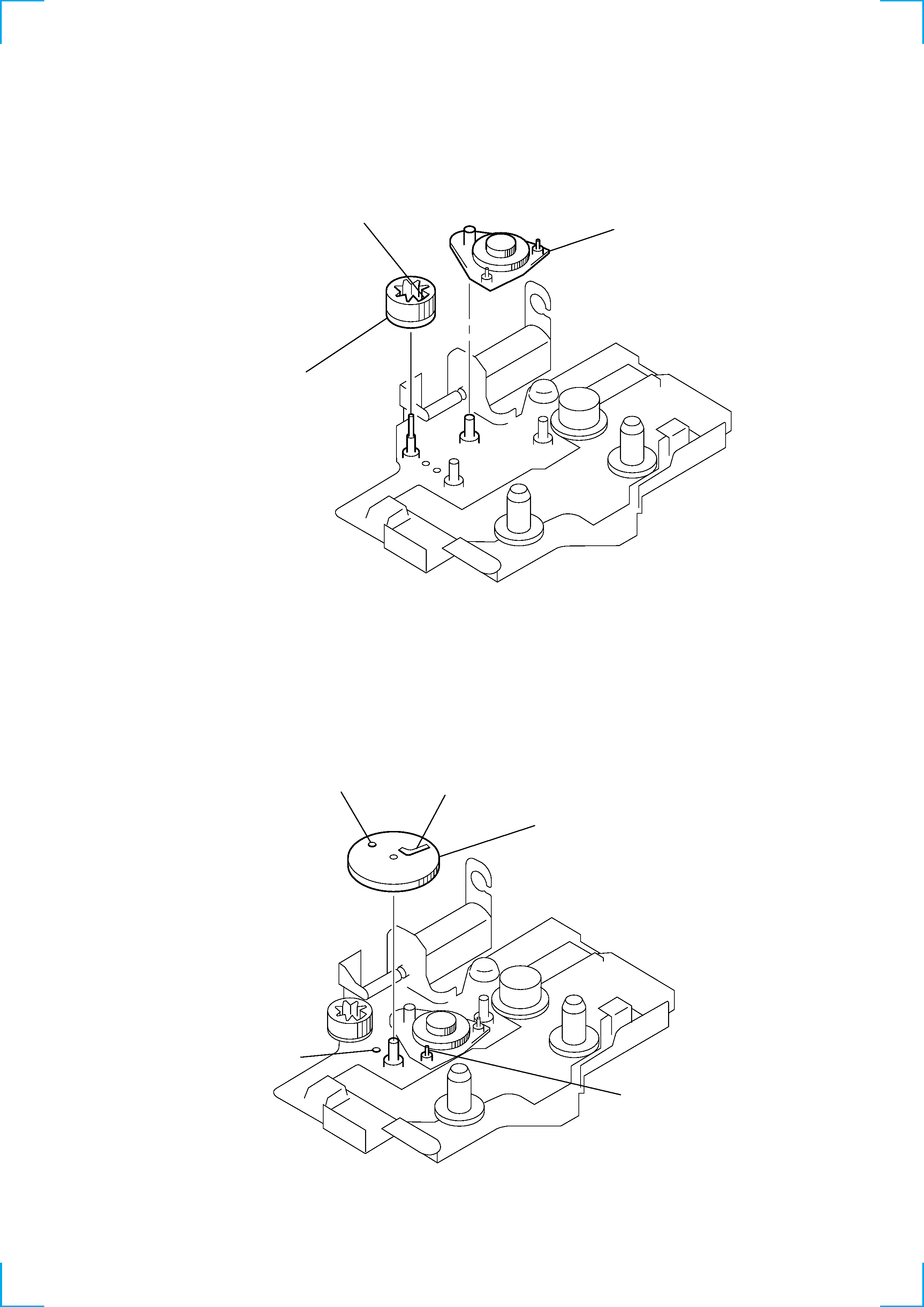
1
gear (LDG-D)
(Position A with B and C with D
and install them.)
D
C
B
A
2
gear (LDG-FB)
(Align part A as
shown in the figure.)
1
arm (drive) assy
Part A
2-2. GEAR (LDG-D)
SECTION 2
ASSEMBLY OF MECHANISM DECK
Note : Follow the assembly procedure in the numerical order given.
2-1. ARM (DRIVE) ASSY