SERVICE MANUAL
US model
FM/AM CASSETTE CAR STEREO
E model
FM/MW/SW CASSETTE CAR STEREO
US Model
E Model
SPECIFICATIONS
XR-F5100
Ver 1.0 2004.03
CA
9-877-608-01
Sony Corporation
2004C05-1
e Vehicle Company
C
2004.03
Published by Sony Engineering Corporation
Model Name Using Similar Mechanism
NEW
Tape Transport Mechanism Type
MG-25L-136
Cassette Player section
Tape track
4-track 2-channel stereo
Wow and flutter
0.08 % (WRMS)
Frequency response
30
- 18,000 Hz
Signal-to-noise ratio
Tuner section
FM
Tuning range
87.5
- 107.9 MHz
Antenna terminal
External antenna connector
Intermediate frequency
10.7 MHz/450 kHz
Usable sensitivity
9 dBf
Selectivity
75 dB at 400 kHz
Signal-to-noise ratio
67 dB (stereo),
69 dB (mono)
Harmonic distortion at 1 kHz
0.5 % (stereo),
0.3 % (mono)
Separation
35 dB at 1 kHz
Frequency response
30
- 15,000 Hz
AM (US model)
Tuning range
530
- 1,710 kHz
Antenna terminal
External antenna connector
Intermediate frequency
10.7 MHz/450 kHz
Sensitivity
30
µV
Power amplifier section
Outputs
Speaker outputs
(sure seal connectors)
Speaker impedance
4
- 8 ohms
Maximum power output
52 W
× 4 (at 4 ohms)
General
Outputs
Audio output terminals
(rear/sub switchable)
Power antenna relay control
terminal
Power amplifier control
terminal
Inputs
Telephone ATT control
terminal
Remote controller input
terminal
BUS control input terminal
BUS audio input terminal
Antenna input terminal
Tone controls
Low:
±10 dB at 60 Hz (XPLOD)
Mid:
±10 dB at 1 kHz (XPLOD)
High:
±10 dB at 10 kHz (XPLOD)
Power requirements
12 V DC car battery
(negative ground)
Dimensions
Approx. 178
× 50 × 177 mm
(7 1/8
× 2 × 7 in)
(w/h/d)
Mounting dimensions
Approx. 182
× 53 × 161 mm
(7 1/4
× 21/8 × 63/8 in)
(w/h/d)
Mass
Approx. 1.2 kg
(2 lb 10 oz)
Supplied accessories
Card remote commander
RM-X115
Parts for installation and
connections (1 set)
Front panel case (1)
Note
This unit cannot be connected to a digital preamplifier
or an equalizer which is Sony BUS system compatible.
Design and specifications are subject to change
without notice.
POWER OUTPUT AND TOTAL HARMONIC DISTORTION
23.2 watts per channel minimum continuous average power into 4 ohms, 4 channels driven from 20 Hz to 20 kHz with no more than 5% total
harmonic distortion.
AUDIO POWER SPECIFICATIONS (US model only)
Cassette type
TYPE II, IV
61 dB
TYPE I
58 dB
Except US model:
US model:
FM tuning interval:
50 kHz/200 kHz switchable
87.5
- 108.0 MHz
(at 50 kHz step)
87.5
- 107.9 MHz
(at 200 kHz step)
MW (Except US model)
Tuning range
MW tuning interval:
9 kHz/10 kHz switchable
531
- 1,602 kHz
(at 9 kHz step)
530
- 1,710 kHz
(at 10 kHz step)
Sensitivity
30
µV
SW (Except US model)
Tuning range
SW tuning interval:
SW1: 2,940
- 7,735 kHz
SW2: 9,500
- 18,135 kHz
(except for
10,140
- 11,575 kHz)
Aerial terminal
External aerial connector
Intermediate frequency
10.7 MHz/450 kHz
Sensitivity
30
µV
2
XR-F5100
Flexible Circuit Board Repairing
· Keep the temperature of the soldering iron around 270 °C dur-
ing repairing.
· Do not touch the soldering iron on the same conductor of the
circuit board (within 3 times).
· Be careful not to apply force on the conductor when soldering
or unsoldering.
Notes on chip component replacement
· Never reuse a disconnected chip component.
· Notice that the minus side of a tantalum capacitor may be dam-
aged by heat.
TABLE OF CONTENTS
SERVICING NOTES ......................................................... 2
1.
GENERAL
Location of Controls .......................................................
3
Setting the Clock .............................................................
3
2.
DISASSEMBLY
2-1. Disassembly Flow ...........................................................
8
2-2. Sub Panel Section ............................................................
8
2-3. Mechanism Deck (MG-25L-136) ...................................
9
2-4. MAIN Board ...................................................................
9
3.
ASSEMBLY
3-1. Assembly Flow ................................................................ 10
3-2. Housing ........................................................................... 11
3-3. Arm (Suction) ................................................................. 11
3-4. Lever (LDG-A)/(LDG-B) ............................................... 12
3-5. Gear (LDG-FT) ............................................................... 12
3-6. Guide (C) ......................................................................... 13
3-7. Mounting Position of Capstan/Reel Motor (M901) ....... 13
4.
MECHANICAL ADJUSTMENTS ....................... 14
5.
ELECTRICAL ADJUSTMENTS
Tape Deck Section .......................................................... 14
Tuner Section .................................................................. 15
6.
DIAGRAMS
6-1. Note for Printed Wiring Boards and
Schematic Diagrams ....................................................... 16
6-2. Printed Wiring Board MAIN Board ........................ 17
6-3. Schematic Diagram MAIN Board (1/3) .................. 18
6-4. Schematic Diagram MAIN Board (2/3) .................. 19
6-5. Schematic Diagram MAIN Board (2/3) .................. 20
6-6. Printed Wiring Board SUB Board ........................... 21
6-7. Schematic Diagram SUB Board .............................. 21
6-8. Printed Wiring Board DISPLAY Board .................. 22
6-7. Schematic Diagram DISPLAY Board ..................... 23
7.
EXPLODED VIEWS
7-1. Shassis Section ................................................................ 27
7-2. Front Panel Section ......................................................... 28
7-3. Mechanism Deck Section (MG-25L-136) ...................... 29
8.
ELECTRICAL PARTS LIST ............................... 30
SERVICING NOTES
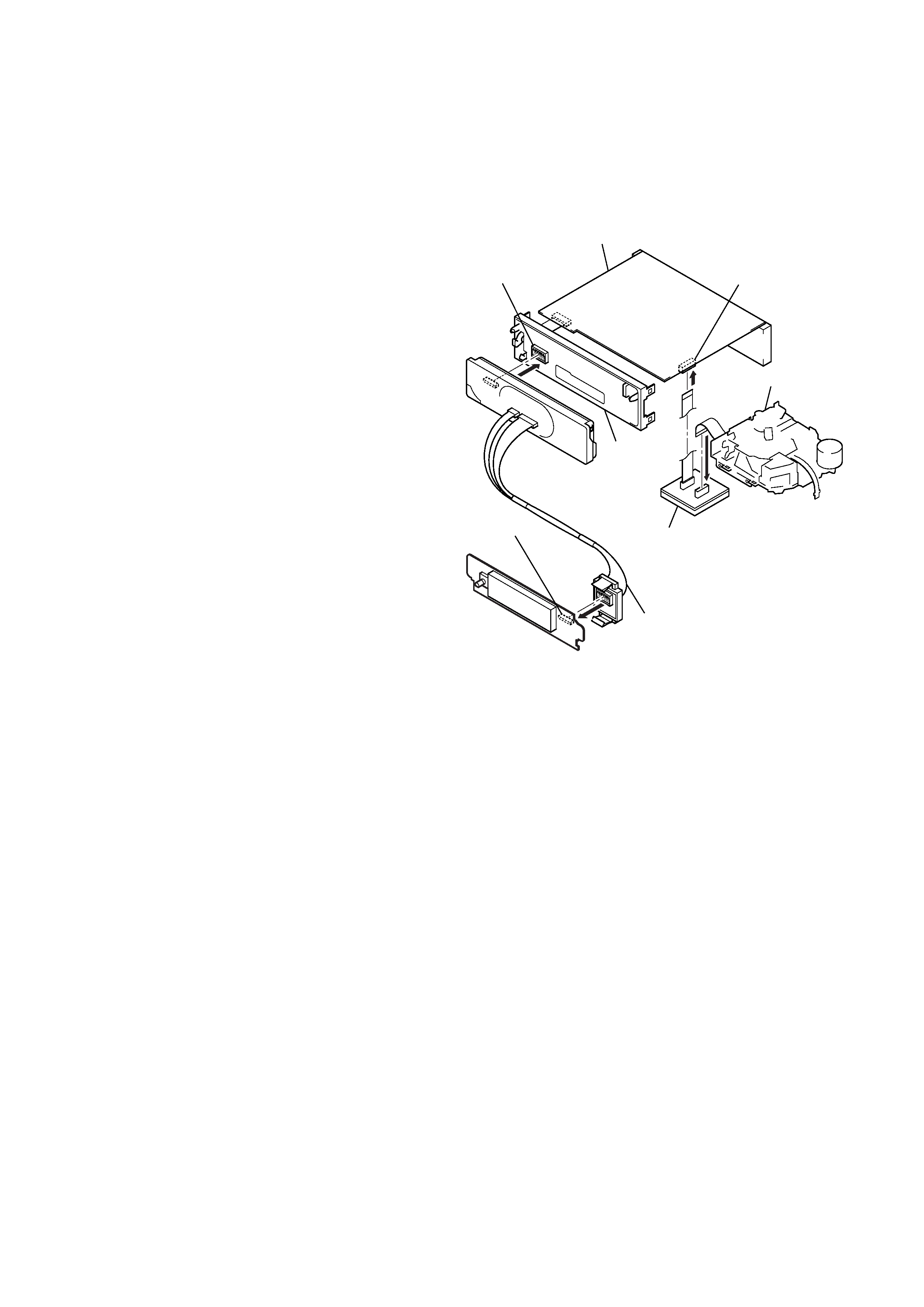
SERVICE POSITION
In checking the control board and main board, prepare two jigs
(extension (MD) cord J-2502-060-1 and
connection cable for F/P to main J-2502-072-1).
MAIN board
SUB board
(CNP801)
mechanism deck
MAIN board (CN351)
DISPLAY board
(CN901)
connect jig
(connection cable
for F/P to MAIN J-2502-071-1)
to the DISPLAY board (CN901) and
SUB board (CNP801).
connect jig
(connection cable J-2502-066-2)
to the MAIN board (CN351) and
mechanism deck.
sub panel
assy
3
XR-F5100
SECTION 1
GENERAL
This section is extracted from
instruction manual.
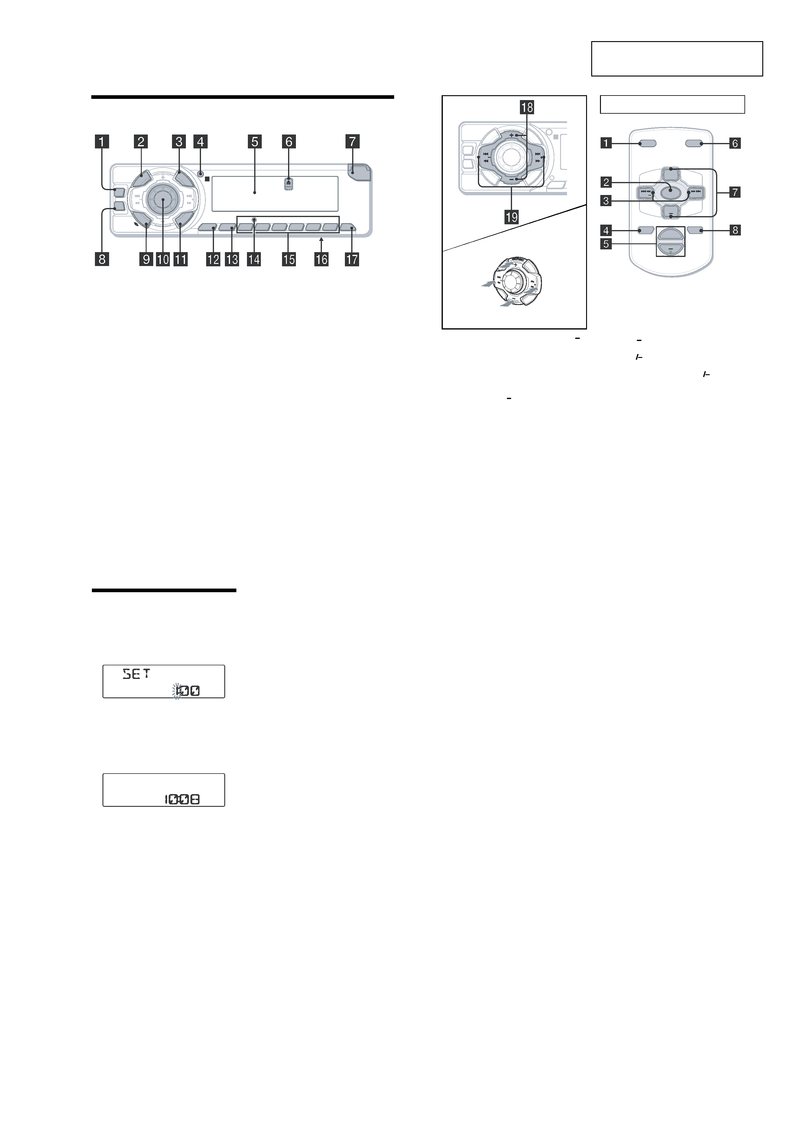
Location of controls
a DSO button
b SOURCE (Power on/Radio/Tape/CD*1/
MD*1) button
To select the source.
c LIST button
d Receptor for the card remote
commander
e Display window
f Z (eject) button (located on the front side
of the unit, behind the front panel)
g OPEN button
h EQ3 button
i MODE (o) button
To change operation.
j Volume control dial/Select button
Rotate to:
- Adjust the volume.
- Adjust settings.
Press to:
- Select items.
k DSPL (display mode change) button
l SENS/MTL button
m BTM button
n RESET button (located on the front side of
the unit, behind the front panel)
o Number buttons
Tape:
(3): REP
(5): BL SKIP
(6): ATA
Radio:
To store stations/receive stored stations.
CD/MD:
(3): REP
(4): SHUF
p Frequency select switch (located on the
bottom of the unit) (Except US)
See "Frequency select switch" in the
Installation/Connections manual.
q OFF (Stop/Power off) button*2
*2
Warning when installing in a car without
an ACC (accessory) position on the
ignition switch
After turning off the ignition, be sure to press
and hold (OFF) on the unit until the display
disappears.
Otherwise, the display does not turn off and this
causes battery drain.
PU
SH
DIA
L
SE
LE
C
T
SO
UR
CE
DISC/PRESET
OPEN
6
5
4
3
BBE
SHUF
ATA
BL SKIP
REP
MTL
2
1
BTM
SENS
EQ3
DS
PL
M
OD
E
DSO
SEEK
SEEK
LIS
T
OFF
r DISC (ALBUM)/PRESET buttons (+/ )
To receive preset stations/change the disc*1,
skip albums*2.
*1 When an optional CD/MD unit is connected.
*2 Available only when an optional CD unit with the
MP3 file control function is connected, and MP3
file is played.
s SEEK buttons ( /+)
To skip tracks/fast-forward, reverse a track/
tune in stations automatically, find a station
manually/select a setting.
The corresponding buttons of the card
remote commander control the same
functions as those on this unit.
a DSPL button
b SOURCE button
c SEEK ( /+) buttons
d OFF button
e VOL (+ ) buttons
f MODE button
g PRESET (DISC/ALBUM) (+ ) buttons
h ATT button
Note
If the display disappears by pressing (OFF), it cannot
be operated with the card remote commander unless
(SOURCE) on the unit is pressed, or a cassette tape is
inserted to activate the unit first.
SEEK
SEEK
PU
SH
DIA
L
SE
LE
C
T
SO
UR
CE
DISC/PRESET
SENS
EQ3
DS
PL
M
OD
E
DSO
SEEK
SEEK
LIS
T
CA
T
(SEEK)
(
-): to select
leftwards/
.
(SEEK)
(+): to select
rightwards/
>
(DISC/PRESET)
(+): to select upwards
(DISC/PRESET)
(
-): to select downwards
Card remote commander RM-X115
ATT
OFF
DSPL
MODE
SOURCE
VOL
+
PRESET
+
PRESET
SEEK
SEEK+
Setting the clock
The clock uses a 12-hour digital indication.
Example: To set the clock to 10:08
1 Press (DSPL) for 2 seconds.
The hour indication flashes.
1 Rotate the volume control dial to set
the hour.
2 Press the select button.
The minute indication flashes.
3 Rotate the volume control dial to set
the minute.
2 Press (DSPL).
The clock starts. After the clock setting is
complete, the display returns to normal play
mode.
4
XR-F5100
Cautions
· This unit is designed for negative ground 12 V
DC operation only.
· Do not get the leads under a screw, or caught
in moving parts (e.g. seat railing).
· Before making connections, turn the car
ignition off to avoid short circuits.
· Connect the yellow and red power input leads
only after all other leads have been connected.
· Run all ground leads to a common ground
point.
· Be sure to insulate any loose unconnected
leads with electrical tape for safety.
Notes on the power supply lead (yellow)
· When connecting this unit in combination with
other stereo components, the connected car
circuit's rating must be higher than the sum of
each component's fuse.
· When no car circuits are rated high enough,
connect the unit directly to the battery.
Parts Iist (1)
· The numbers in the list are keyed to those in
the instructions.
· The bracket 1 and the protection collar 3 are
attached to the unit before shipping. Before
mounting the unit, use the release keys 5 to
remove the bracket 1 and the protection collar
3
from the unit. For details, see "Removing
the protection collar and the bracket (4)" on
the reverse side of the sheet.
· Keep the release keys 5 for future use as
they are also necessary if you remove the
unit from your car.
Caution
Handle the bracket 1 carefully to avoid injuring
your fingers.
Note
Before installing, make sure that the catches on
both sides of the bracket 1 are bent inwards 2 mm
(3/32 in). If the catches are straight or bent outwards,
the unit will not be installed securely and may spring
out.
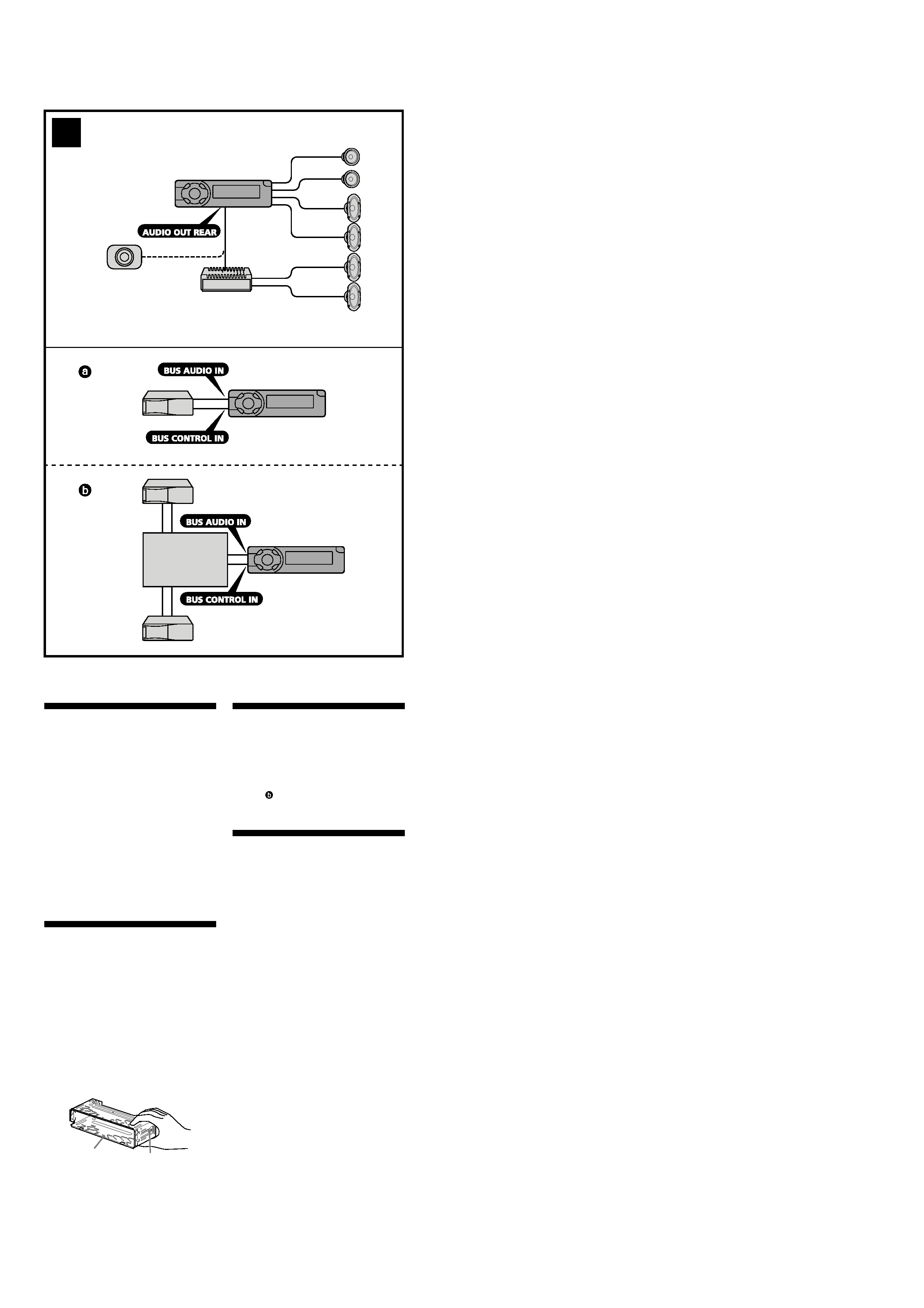
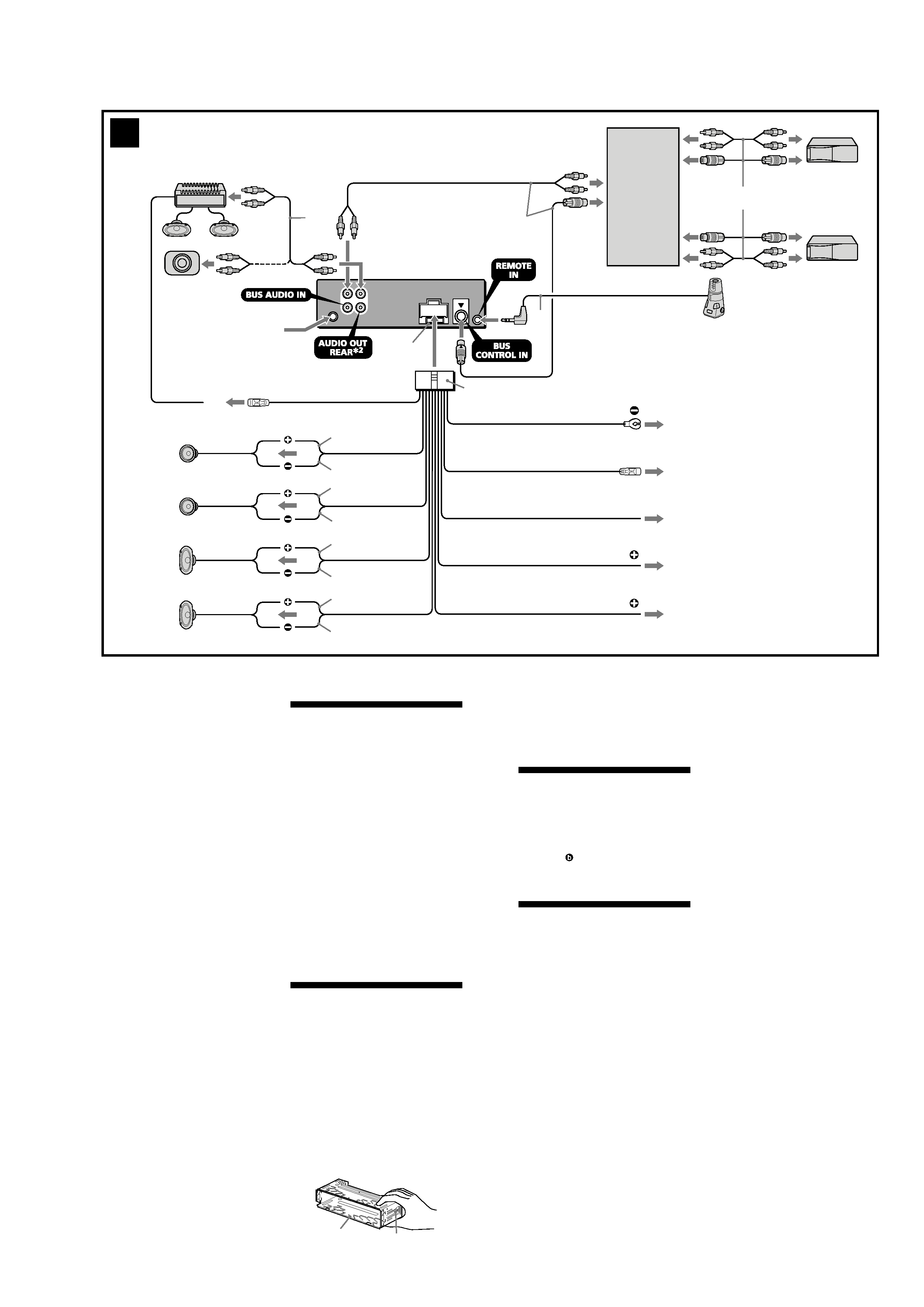
Connection example (2)
Notes (2-A)
· Be sure to connect the ground lead before
connecting the amplifier.
· If you connect an optional power amplifier and do
not use the built-in amplifier, the beep sound will
be deactivated.
Tip (2-B-
)
For connecting two or more CD/MD changers, the
source selector XA-C30 (optional) is necessary.
Connection diagram (3)
1 To a metal surface of the car
First connect the black ground lead, then
connect the yellow and red power input leads.
2 To the power antenna control lead or power
supply lead of antenna booster amplifier
Notes
· It is not necessary to connect this lead if there
is no power antenna or antenna booster, or
with a manually-operated telescopic antenna.
· When your car has a built-in FM/AM antenna in
the rear/side glass, see "Notes on the control
and power supply leads."
3 To AMP REMOTE IN of an optional power
amplifier
This connection is only for amplifiers. Connecting
any other system may damage the unit.
4 To the interface cable of a car telephone
5 To the +12 V power terminal which is energized
in the accessory position of the ignition key
switch
Notes
· If there is no accessory position, connect to the
+12 V power (battery) terminal which is
energized at all times.
Be sure to connect the black ground lead to a
metal surface of the car first.
· When your car has a built-in FM/AM antenna in
the rear/side glass, see "Notes on the control
and power supply leads."
6 To the +12 V power terminal which is energized
at all times
Be sure to connect the black ground lead to a
metal surface of the car first.
Catch
1
Source selector*
Sélecteur de source*
XA-C30
* not supplied
non fourni
2
A
B
5
XR-F5100
L
R
Précautions
· Cet appareil est exclusivement conçu pour
fonctionner sur une tension de 12 V CC avec
masse négative.
· Évitez de fixer des vis sur les câbles ou de
coincer ceux-ci dans des pièces mobiles (par
exemple, armature de siège).
· Avant d'effectuer les raccordements, éteignez
le moteur pour éviter un court-circuit.
· Raccordez les fils d'entrée d'alimentation
jaune et rouge seulement après avoir terminé
tous les autres raccordements.
· Rassemblez tous les fils de terre en un point
de masse commun.
· Pour des raisons de sécurité, veillez à isoler
avec du ruban isolant tout fil lâche non
raccordé.
Remarques sur le cordon d'alimentation
(jaune)
· Lorsque cet appareil est raccordé à d'autres
éléments stéréo, la valeur nominale du circuit
utilisé de la voiture raccordée doit être
supérieure à la somme des fusibles de chaque
élément.
· Si aucun circuit de la voiture n'est assez
puissant, raccordez directement l'appareil à la
batterie.
Liste des composants (1)
· Les numéros de la liste correspondent à ceux
des instructions.
· Le support 1 et le tour de protection 3 sont
fixés à l'appareil avant de quitter l'usine.
Avant le montage de l'appareil, utilisez les clés
de déblocage 5 pour détacher le support 1 et
le tour de protection 3 de l'appareil. Pour de
plus amples informations, reportez-vous à la
section « Retrait du tour de protection et du
support (4) » au verso.
· Conservez les clés de déblocage 5 pour une
utilisation ultérieure car vous en aurez
également besoin pour retirer l'appareil de
votre véhicule.
Attention
Manipulez précautionneusement le support 1
pour éviter de vous blesser aux doigts.
Remarque
Avant l'installation, assurez-vous que les loquets des
deux côtés du support 1 sont bien pliés de 2 mm
(3/32 po) vers l'intérieur. Si les loquets sont droits ou
pliés vers l'extérieur, l'appareil ne peut pas être fixé
solidement et peut se détacher.
Exemple de raccordement (2)
Remarques (2-A)
· Raccordez d'abord le fil de masse avant de
raccorder l'amplificateur.
· Si vous raccordez un amplificateur de puissance en
option et que vous n'utilisez pas l'amplificateur
intégré, le bip sonore est désactivé.
Conseil (2-B-
)
Dans le cas du raccordement de deux changeurs de
CD/MD ou plus, le sélecteur de source XA-C30 (en
option) est requis.
Schéma de raccordement (3)
1 À un point métallique de la voiture
Branchez d'abord le fil de masse noir et, ensuite,
les fils d'entrée d'alimentation jaune et rouge.
2 Vers le fil de commande de l'antenne électrique
ou le fil d'alimentation de l'amplificateur
d'antenne
Remarques
· Il n'est pas nécessaire de raccorder ce fil s'il n'y a
pas d'antenne électrique ni d'amplificateur
d'antenne, ou avec une antenne télescopique
manuelle.
· Si votre voiture est équipée d'une antenne FM/
AM intégrée dans la vitre arrière/latérale, voir
« Remarques sur les fils de commande et
d'alimentation ».
3 Au niveau du AMP REMOTE IN de l'amplificateur
de puissance en option
Ce raccordement s'applique uniquement aux
amplificateurs. Le branchement de tout autre
système risque d'endommager l'appareil.
4 Vers le cordon de liaison d'un téléphone de
voiture
5 À la borne +12 V qui est alimentée quand la clé
de contact est sur la position accessoires
Remarques
· S'il n'y a pas de position accessoires, raccordez la
borne d'alimentation (batterie) +12 V qui est
alimentée en permanence.
Raccordez d'abord le fil de masse noir à un
point métallique du véhicule.
· Si votre voiture est équipée d'une antenne FM/
AM intégrée dans la vitre arrière/latérale, voir
« Remarques sur les fils de commande et
d'alimentation ».
1
Loquet
6 À la borne +12 V qui est alimentée en
permanence
Raccordez d'abord le fil de masse noir à un point
métallique du véhicule.
Remarques sur les fils de commande et
d'alimentation
· Le fil de commande de l'antenne électrique (bleu)
fournit une alimentation de +12 V CC lorsque vous
mettez la radio sous tension.
· Lorsque votre voiture est équipée d'une antenne
FM/AM intégrée dans la vitre arrière/latérale,
raccordez le fil de commande de l'antenne (bleu)
ou l'entrée d'alimentation des accessoires (rouge) à
la borne d'alimentation de l'amplificateur
d'antenne existant. Pour plus de détails, consultez
votre détaillant.
· Une antenne électrique sans boîtier de relais ne
peut pas être utilisée avec cet appareil.
Raccordement pour la conservation de la mémoire
Lorsque le fil d'entrée d'alimentation jaune est
raccordé, le circuit de la mémoire est alimenté en
permanence même si la clé de contact est sur la
position d'arrêt.
Remarques sur le raccordement des haut-parleurs
· Avant de raccorder les haut-parleurs, mettez
l'appareil hors tension.
· Utilisez des haut-parleurs ayant une impédance de
4 à 8 ohms avec une capacité électrique adéquate
pour éviter de les endommager.
· Ne raccordez pas les bornes du système de haut-
parleurs au châssis de la voiture et ne raccordez pas
les bornes des haut-parleurs droit à celles du haut-
parleur gauche.
· Ne raccordez pas le câble de masse de cet appareil à
la borne négative (
-) de l'enceinte.
· N'essayez pas de raccorder les haut-parleurs en
parallèle.
· Raccordez uniquement des haut-parleurs passifs. Le
raccordement de haut-parleurs actifs (avec
amplificateurs intégrés) aux bornes des haut-
parleurs peut endommager l'appareil.
· Pour éviter tout dysfonctionnement, n'utilisez pas
les fils des haut-parleurs intégrés installés dans
votre voiture si l'appareil partage un fil négatif
commun (
-) pour les haut-parleurs droit et gauche.
· Ne raccordez pas entre eux les cordons des haut-
parleurs de l'appareil.
Remarque sur le raccordement
Si les haut-parleurs et l'amplificateur ne sont pas
raccordés correctement, le message « FAILURE »
s'affiche. Dans ce cas, assurez-vous que les haut-
parleurs et l'amplificateur sont bien raccordés.
Notes on the control and power supply leads
· The power antenna control lead (blue) supplies
+12 V DC when you turn on the tuner.
· When your car has built-in FM/AM antenna in the
rear/side glass, connect the power antenna control
lead (blue) or the accessory power input lead (red)
to the power terminal of the existing antenna
booster. For details, consult your dealer.
· A power antenna without a relay box cannot be
used with this unit.
Memory hold connection
When the yellow power input lead is connected,
power will always be supplied to the memory circuit
even when the ignition switch is turned off.
Notes on speaker connection
· Before connecting the speakers, turn the unit off.
· Use speakers with an impedance of 4 to 8 ohms,
and with adequate power handling capacities to
avoid its damage.
· Do not connect the speaker terminals to the car
chassis, or connect the terminals of the right
speakers with those of the left speaker.
· Do not connect the ground lead of this unit to the
negative (
-) terminal of the speaker.
· Do not attempt to connect the speakers in parallel.
· Connect only passive speakers. Connecting active
speakers (with built-in amplifiers) to the speaker
terminals may damage the unit.
· To avoid a malfunction, do not use the built-in
speaker leads installed in your car if the unit shares
a common negative (
-) lead for the right and left
speakers.
· Do not connect the unit's speaker leads to each
other.
Note on connection
If speaker and amplifier are not connected correctly,
"FAILURE" appears in the display. In this case, make
sure the speaker and amplifier are connected
correctly.
3
Supplied with XA-C30
Fourni avec le XA-C30
Source selector
(not supplied)
Sélecteur de source
(non fourni)
XA-C30
AMP REM
Max. supply current 0.3 A
Courant max. fourni 0,3 A
Fuse (10 A)
Fusible (10 A)
Blue/white striped
Rayé bleu/blanc
White
Blanc
Green
Vert
Purple
Mauve
White/black striped
Rayé blanc/noir
Gray/black striped
Rayé gris/noir
Green/black striped
Rayé vert/noir
Purple/black striped
Rayé mauve/noir
Gray
Gris
Supplied with the CD/MD changer
Fourni avec le changeur de CD/MD
3
*3
from car antenna
à partir de l'antenne de la voiture
Left
Gauche
Right
Droit
Left
Gauche
Right
Droit
2
5
6
4
ANT REM
4
Red
Rouge
Yellow
Jaune
Black
Noir
Blue
Bleu
Light blue
Bleu ciel
Max. supply current 0.1 A
Courant max. fourni 0,1 A
ATT
1
*1
*1 RCA pin cord (not supplied)
*2 AUDIO OUT can be switched to REAR
or SUB.
For details, see the supplied operating
instructions.
*3 Insert with the cord upwards.
*1 Cordon à broche RCA (non fourni)
*2 AUDIO OUT peut être commuté sur
REAR ou SUB.
Pour obtenir plus de détails, reportez-
vous au mode d'emploi fourni.
*3 Insérez avec le câble vers le haut.