SERVICE MANUAL
FM/AM CASSETTE CAR STEREO
US Model
Canadian Model
SPECIFICATIONS
XR-CA430X
Ver 1.1 2003.01
9-873-495-02
Sony Corporation
2003A0500-1
e Vehicle Company
C
2003.01
Published by Sony Engineering Corporation
Model Name Using Similar Mechanism
XR-CA400
Tape Transport Mechanism Type
MG-25F-136
Cassette Player section
Tape track
4-track 2-channel stereo
Wow and flutter
0.08 % (WRMS)
Frequency response
30 18,000 Hz
Signal-to-noise ratio
Tuner section
FM
Tuning range
87.5 107.9 MHz
Antenna terminal
External antenna connector
Intermediate frequency
10.7 MHz
Usable sensitivity
11 dBf
Selectivity
75 dB at 400 kHz
Signal-to-noise ratio
65 dB (stereo),
68 dB (mono)
Harmonic distortion at 1 kHz
0.7 % (stereo),
0.5 % (mono)
Separation
33 dB at 1 kHz
Frequency response
30 15,000 Hz
AM
Tuning range
530 1,710 kHz
Antenna terminal
External antenna connector
Intermediate frequency
10.7 MHz/450 kHz
Sensitivity
30
µV
Power amplifier section
Outputs
Speaker outputs
(sure seal connectors)
Speaker impedance
4 8 ohms
Maximum power output 50 W
× 4 (at 4 ohms)
General
Outputs
Audio outputs (1)
Power antenna relay control
terminal
Power amplifier control
terminal
Inputs
BUS control input terminal
BUS audio input terminal
Antenna input terminal
Tone controls
Bass
±10 dB at 20 Hz
Treble
±10 dB at 20 kHz
Power requirements
12 V DC car battery
(negative ground)
Dimensions
Approx. 178
× 50 × 178
mm (71/8
× 2 × 71/8 in.)
(w/h/d)
Mounting dimensions
Approx. 182
× 53 × 161
mm (71/4
× 21/8 × 63/8 in.)
(w/h/d)
Mass
Approx. 1.2 kg (2 lb 10 oz)
Supplied accessories
Parts for installation and
connections (1 set)
Front panel case (1)
Note
This unit cannot be connected to a digital preamplifier
or an equalizer.
Design and specifications are subject to change
without notice.
POWER OUTPUT AND TOTAL HARMONIC DISTORTION
23 watts per channel minimum continuous average power into 4 ohms,
4 channels driven from 20 Hz to 20 kHz with no more than 5% total harmonic distortion.
AUDIO POWER SPECIFICATIONS (US model)
Cassette type
TYPE II, IV
61 dB
TYPE I
58 dB

2
XR-CA430X
TABLE OF CONTENTS
1.
GENERAL
Location of Controls .......................................................
3
Setting the clock ..............................................................
3
Installation/Connections .................................................
4
2.
DISASSEMBLY
2-1. Disassembly Flow ...........................................................
8
2-2. Cover ...............................................................................
8
2-3. Mechanism Deck (MG-25F-136) ...................................
9
2-4. MAIN Board ...................................................................
9
2-5. Heat Sink ......................................................................... 10
3.
ASSEMBLY OF MECHANISM DECK
3-1. Assembly Flow ................................................................ 11
3-2. Housing ........................................................................... 12
3-3. Arm (Suction) ................................................................. 12
3-4. Lever (LDG-A)/(LDG-B) ............................................... 13
3-5. Gear (LDG-FT) ............................................................... 13
3-6. Guide (C) ......................................................................... 14
3-7. Mounting Position of Capstan/Reel Motor (M901) ....... 14
4.
MECHANICAL ADJUSTMENTS ....................... 15
5.
ELECTRICAL ADJUSTMENTS
Tape Deck Section .......................................................... 15
Tuner Section .................................................................. 15
6.
DIAGRAMS
6-1. Note for Printed Wiring Boards and
Schematic Diagrams ....................................................... 15
6-2. Printed Wiring Board MAIN Board ......................... 16
6-3. Schematic Diagram MAIN Board (1/3) ................... 17
6-4. Schematic Diagram MAIN Board (2/3) ................... 18
6-5. Schematic Diagram MAIN Board (3/3) ................... 19
6-6. Printed Wiring Board KEY Board ............................ 20
6-7. Schematic Diagram KEY Board .............................. 21
6-8. IC Pin Function Description ........................................... 24
7.
EXPLODED VIEWS
7-1. Chassis Section ............................................................... 27
7-2. Front Panel Section ......................................................... 28
7-3. Main Board Section ........................................................ 29
7-4. Mechanism Deck Section (MG-25F-136) ...................... 30
8.
ELECTRICAL PARTS LIST ............................... 31
Notes on chip component replacement
· Never reuse a disconnected chip component.
· Notice that the minus side of a tantalum capacitor may be dam-
aged by heat.
Flexible Circuit Board Repairing
· Keep the temperature of the soldering iron around 270 °C dur-
ing repairing.
· Do not touch the soldering iron on the same conductor of the
circuit board (within 3 times).
· Be careful not to apply force on the conductor when soldering
or unsoldering.
3
XR-CA430X
SECTION 1
GENERAL
This section is extracted from
instruction manual.
4
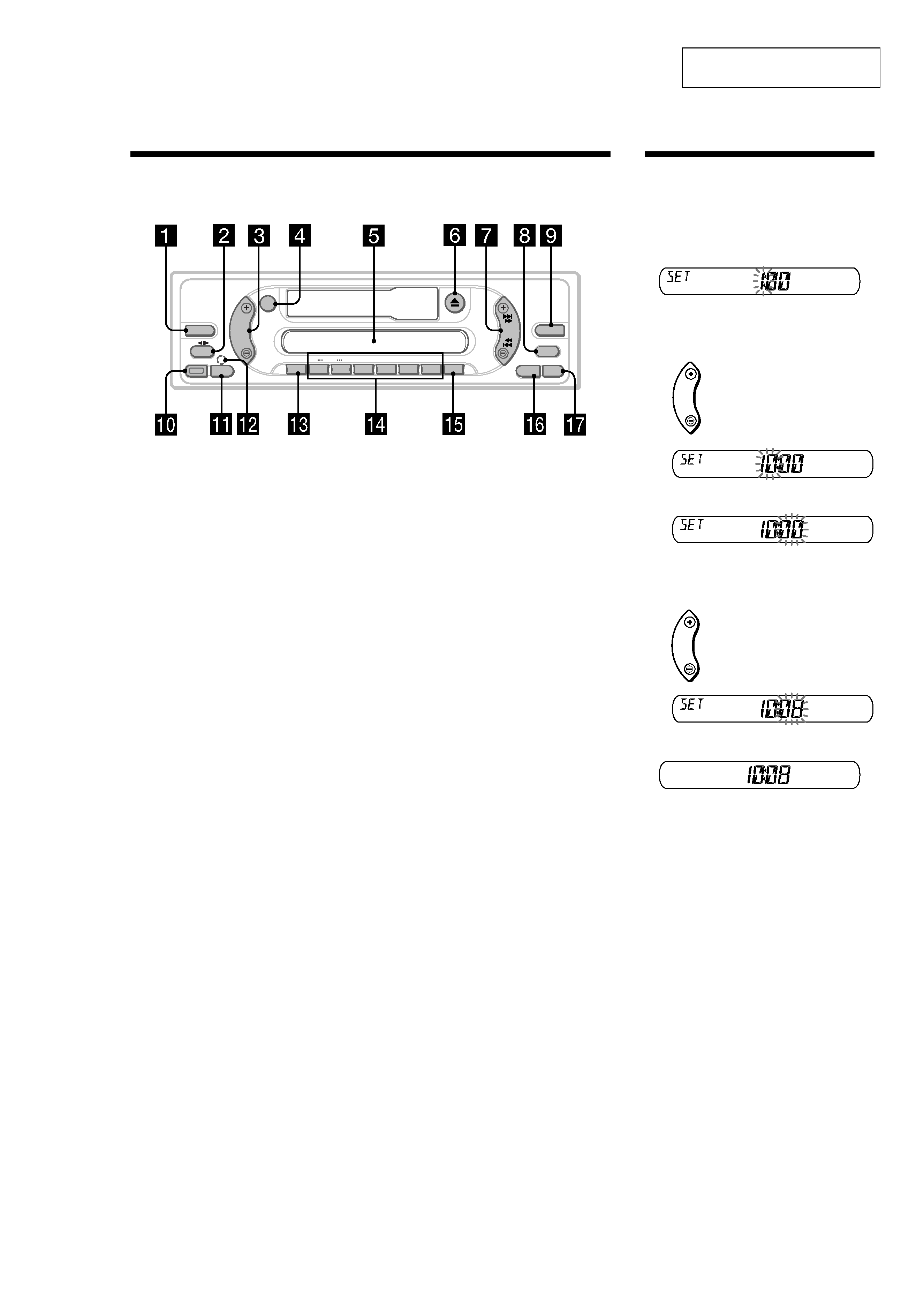
Location of controls
Refer to the pages listed for details.
a SOURCE (Power on/Tape/Radio/CD/
MD) select button
b MODE (
o) button
Selecting the source.
c VOL +/ button
d ATT (attenuate) button
e Display window
f
Z (eject) button 8
g SEEK/AMS button
Tape:
Fast-forwarding, reversing a tape.
Radio:
Tuning in stations automatically.
Finding a station manually.
CD (MP3 files)/MD:
Skipping tracks.
h MBP (My Best sound Position) button
12
i D-BASS button 12
j RELEASE (front panel release) button
k SEL (select) button
Selecting items.
l RESET button (located on the front side of
the unit, behind the front panel)
6
m SENS button
Storing the stations with the strongest
signals.
n Number buttons
Tape:
(3): REP (Repeat)
(5): BL SKIP (Blank Skip)
(6): ATA (Automatic Tuner Activation)
Radio:
Storing the desired station on each number
button.
CD (MP3 files)/MD:
(1): DISC
(2): DISC +
(3): REP (Repeat)
(4): SHUF (Shuffle)
MP3 files:
(5): ALBM
(6): ALBM +
o BTM/MTL (Best Tuning Memory/Metal)
button
9
p DSPL (display mode change) button
q OFF (Stop/Power off) button*
*
Warning when installing in a car without
an ACC (accessory) position on the
ignition switch
After turning off the ignition, be sure to press
(OFF) on the unit for 2 seconds to turn off
the clock display.
Otherwise, the clock display does not turn off
and this causes battery drain.
XR-CA430X
SOURCE
ATT
VOL
SENS
DISC
REP
SHUF BL SKIP/ ALBM
-
+/ATA MTL
+
MODE
SEL
RELEASE
12
3
4
5
6
D-BASS
SEEK
AMS
BTM
MBP
OFF
DSPL
Setting the clock
The clock uses a 12-hour digital indication.
Example: To set the clock to 10:08
1 Press (DSPL) for 2 seconds.
The hour indication flashes.
1Press either side of (VOL) to set the
hour.
2Press (SEL).
The minute indication flashes.
3Press either side of (VOL) to set the
minute.
2 Press (DSPL).
The clock starts.
After the clock setting is completed, the
display returns to normal play mode.
VOL
to go forward
to go back
VOL
to go forward
to go back
4
XR-CA430X
2
B
BUS AUDIO IN
BUS CONTROL IN
AUDIO OUT REAR
BUS CONTROL IN
BUS AUDIO IN
A
*
not supplied
non fourni
Source selector
*
Sélecteur de source
Cautions
· This unit is designed for negative ground 12 V
DC operation only.
· Do not get the wires under a screw, or caught
in moving parts (e.g., seat railing).
· Before making connections, turn the car
ignition off to avoid short circuits.
· Connect the yellow and red power input leads
only after all other leads have been connected.
· Run all ground wires to a common ground
point.
· Be sure to insulate any loose unconnected
wires with electrical tape for safety.
Notes on the power supply cord (yellow)
· When connecting this unit in combination with
other stereo components, the connected car
circuit's rating must be higher than the sum of
each component's fuse.
· When no car circuits are rated high enough,
connect the unit directly to the battery.
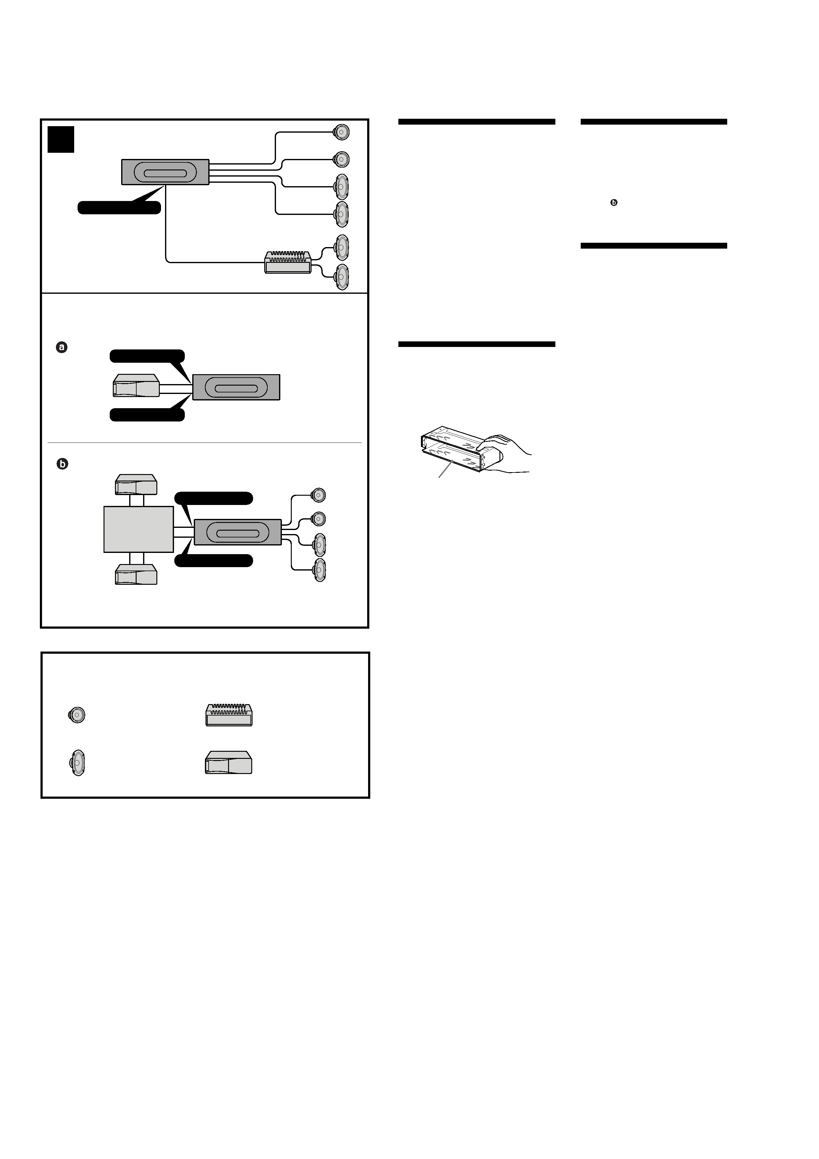
Parts Iist (
1)
The numbers in the list are keyed to those in the
instructions.
Caution
Handle the bracket
1 carefully to avoid injuring
your fingers.
Connection example (
2)
Notes (
2-A)
· Be sure to connect the ground cord before
connecting the amplifier.
· If you connect an optional power amplifier and
do not use the built-in amplifier, the beep
sound will be deactivated.
Tip (
2-B- )
For connecting two or more CD/MD changers,
the source selector XA-C30 (optional) is
necessary.
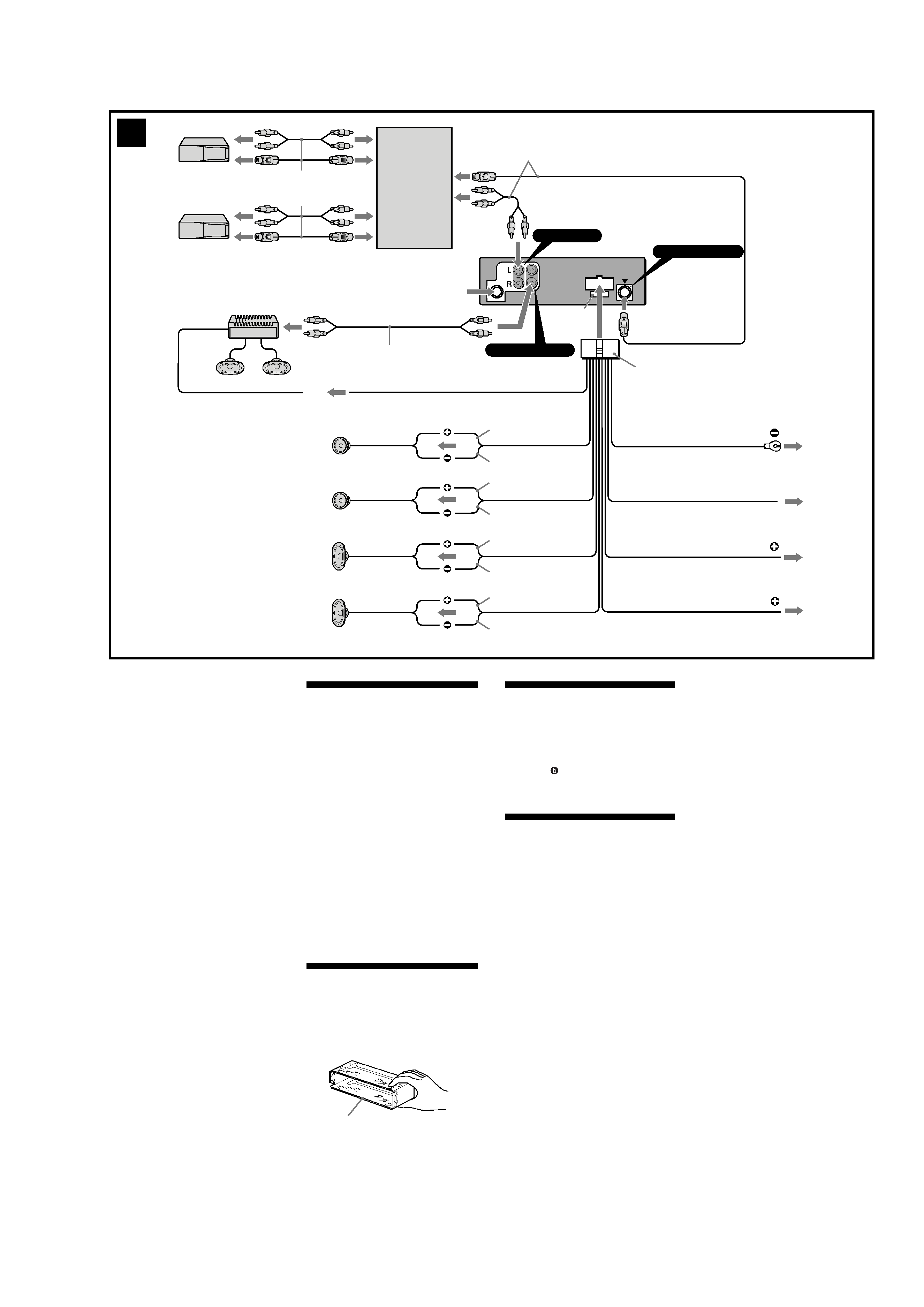
Connection diagram (
3)
1 To a metal surface of the car
First connect the black ground lead, then
connect the yellow and red power input
leads.
2 To the power antenna control lead or power
supply lead of antenna booster amplifier
Notes
· It is not necessary to connect this lead if
there is no power antenna or antenna
booster, or with a manually-operated
telescopic antenna.
· When your car has a built-in FM/AM
antenna in the rear/side glass, see "Notes
on the control and power supply leads."
3 To AMP REMOTE IN of an optional power
amplifier
This connection is only for amplifiers.
Connecting any other system may damage
the unit.
4 To the +12 V power terminal which is
energized in the accessory position of the
ignition key switch
Notes
· If there is no accessory position, connect to
the +12 V power (battery) terminal which is
energised at all times.
Be sure to connect the black ground to it
first.
· When your car has a built-in FM/AM
antenna in the rear/side glass, see "Notes
on the control and power supply leads."
5 To the +12 V power terminal which is
energised at all times
Be sure to connect the black ground to it
first.
1
Equipment used in illustrations (not supplied)
Appareils utilisés dans les illustrations (non fournis)
Power amplifier
Amplificateur de puissance
CD/MD changer
Changeur de CD/MD
Front speaker
Haut-parleur frontal
Rear speaker
Haut-parleur arrière
Installation/Connections
5
XR-CA430X
Précautions
·Cet appareil est exclusivement conçu pour
fonctionner sur une tension de 12 V CC avec
masse négative.
·Évitez de fixer des vis sur les câbles ou de
coincer ceux-ci dans des pièces mobiles (par
exemple, armature de siège).
·Avant d'effectuer des raccordements, éteignez
le moteur pour éviter les courts-circuits.
·Brancher les fils d'entrée d'alimentation jaune
et rouge seulement après avoir terminé tous les
autres branchements.
·Rassembler tous les fils de terre en un point
de masse commun.
·Veillez à fixer avec du ruban isolant tout fil
lâche non raccordé.
Remarques sur le cordon d'alimentation
(jaune)
·Lorsque cet appareil est raccordé à d'autres
éléments stéréo, la valeur nominale du circuit
raccordé de la voiture doit être supérieure à la
somme des fusibles de chaque élément.
·Si aucun circuit de la voiture n'est assez
puissant, raccordez directement l'appareil à la
batterie.
Liste des composants (
1)
Les numéros de l'illustration correspondent à
ceux des instructions.
Attention
Manipulez avec précaution le support
1 pour
éviter de vous blesser aux doigts.
3
Notes on the control and power supply leads
· The power antenna control lead (blue) supplies
+12 V DC when you turn on the tuner.
· When your car has built-in FM/AM antenna in the
rear/side glass, connect the power antenna control
lead (blue) or the accessory power input lead (red)
to the power terminal of the existing antenna
booster. For details, consult your dealer.
· A power antenna without relay box cannot be
used with this unit.
Memory hold connection
When the yellow power input lead is connected,
power will always be supplied to the memory circuit
even when the ignition key is turned off.
Notes on speaker connection
· Before connecting the speakers, turn the unit off.
· Use speakers with an impedance of 4 to 8 ohms,
and with adequate power handling capacities to
avoid its damage.
· Do not connect the speaker terminals to the car
chassis, or connect the terminals of the right
speakers with those of the left speaker.
· Do not connect the ground lead of this unit to the
negative () terminal of the speaker.
· Do not attempt to connect the speakers in parallel.
· Connect only passive speakers. Connecting active
speakers (with built-in amplifiers) to the speaker
terminals may damage the unit.
· To avoid a malfunction, do not use the built-in
speaker wires installed in your car if the unit
shares a common negative () lead for the right
and left speakers.
· Do not connect the unit's speaker cords to each
other.
Exemple de raccordement (
2)
Remarques (
2-A)
· Raccordez d'abord le fil de masse avant de
connecter l'amplificateur.
· Si vous raccordez un amplificateur de puissance et
que vous n'utilisez pas l'amplificateur intégré, le
bip sonore est désactivé.
Conseil (
2-B- )
Dans le cas du raccordement de deux changeurs de
CD/MD ou plus, le sélecteur de source XA-C30
(optionnel) est indispensable.
Schémas de connexion (
3)
1 à un point métallique de la voiture
Branchez d`abord le fil de masse noir et, ensuite,
les fils d`entrée d`alimentation jaune et rouge.
2 vers le fil de commande de l`antenne électrique
ou le fil d`alimentation de l`amplificateur
d`antenne
Remarque
· Il n'est pas nécessaire de raccorder ce fil s'il n'y
a pas d'antenne électrique ni d'amplificateur
d'antenne, ou avec une antenne télescopique
manuelle.
· Si votre voiture est équipée d'une antenne FM/
AM intégrée dans la vitre arrière/latérale, voir
"Remarques sur les fils de commande et
d'alimentation".
3 pour effectuer le raccordement à AMP REMOTE
IN de l'amplificateur de puissance en option
Cette connexion s'applique uniquement aux
amplificateurs. Le branchement de tout autre
système risque d'endommager l'appareil.
4 à la borne +12 V qui est alimentée quand la clé
de contact est sur la position accessoires
Remarque
· S'il n'y a pas de position accessoires, raccordez
la borne d'alimentation (batterie) +12 V qui est
toujours sous tension.
Raccordez d`abord le fil de masse noir.
· Si votre voiture est équipée d'une antenne FM/
AM intégrée dans la vitre arrière/latérale, voir
"Remarques sur les fils de commande et
d'alimentation".
5 à la borne +12 V qui est alimentée en
permanence
Ra
ccordez d`abord le fil de masse noir.
BUS
AUDIO IN
AUDIO
OUT
1
2
4
5
Supplied with XA-C30
Fourni avec le XA-C30
Blue
Bleu
Red
Rouge
Yellow
Jaune
5
Black
Noir
RCA pin cord (not supplied)
Cordon à broche RCA (non fourni)
Max. supply current 0.1 A
Courant max. fourni 0,1 A
from car antenna
de l'antenne de la voiture
Fuse (10 A)
Fusible (10 A)
BUS AUDIO IN
AUDIO OUT REAR
AMP REM
ANT REM
BUS CONTROL IN
XR-CA430X
Blue/white striped
Rayé bleu/blanc
Max. supply current 0.3 A
Courant max. fourni 0,3 A
White
Blanc
Gray
Gris
Green
Vert
Purple
Mauve
White/black striped
Rayé blanc/noir
Gray/black striped
Rayé gris/noir
Green/black striped
Rayé vert/noir
Purple/black striped
Rayé mauve/noir
Remarques sur les fils de commande et
d'alimentation
· Le fil de commande de l'antenne électrique (bleu)
fournit une alimentation de + 12 V CC lorsque vous
mettez l'appareil sous tension.
· Si votre voiture est équipée d'une antenne FM/AM
intégrée dans la vitre arrière latérale, vous devez
raccorder le fil de commande d'antenne électrique
(bleu) ou le fil d'entrée d'alimentation d'accessoire
(rouge) à la borne d'alimentation de l'amplificateur
d'antenne existant. Pour plus de détails, consultez
votre détaillant.
· Une antenne électrique sans boitier de relais ne
peut pas être utilisée avec cet appareil.
Connexion pour la conservation de la mémoire
Lorsque le fil d'entrée d'alimentation jaune est
raccordé, le circuit de la mémoire est alimenté en
permanence même si la clé de contact est sur la
position d'arrêt.
Remarques sur le raccordement des haut-parleurs
· Avant de raccorder les haut-parleurs, mettez
l'appareil hors tension.
· Utilisez des haut-parleurs ayant une impédance de
4 à 8 ohms et une capacité adéquate pour éviter de
les endommager.
· Ne raccordez pas les bornes du système de haut-
parleur au châssis de la voiture et ne raccordez pas
les bornes du haut-parleur droit à celles du haut-
parleur gauche.
· Ne raccordez pas le câble de masse de cet appareil à
la borne négative () de l'enceinte.
· N'essayez pas de raccorder les haut-parleurs en
parallèle.
· Raccordez uniquement des haut-parleurs passifs. Le
raccordement de haut-parleurs actifs (avec
amplificateurs intégrés) aux bornes des haut-
parleurs peut endommager l'appareil.
· Pour éviter tout dysfonctionnement, n'utilisez pas
les fils des haut-parleurs intégrés installés dans
votre voiture si l'appareil partage un fil négatif
commun () pour les haut-parleurs droit et gauche.
· Ne raccordez pas entre eux les fils des haut-parleurs
de l'appareil.
Supplied with the CD/MD changer
Fourni avec le changeur de CD/MD
Source selector
Sélecteur de source
XA-C30
Left
Gauche
Right
Droit
Left
Gauche
Right
Droit
3
1