1
Model Name Using Similar Mechanism
XR-C8100R
Tape Transport Mechanism Type
MG-25D-136
SERVICE MANUAL
AEP Model
UK Model
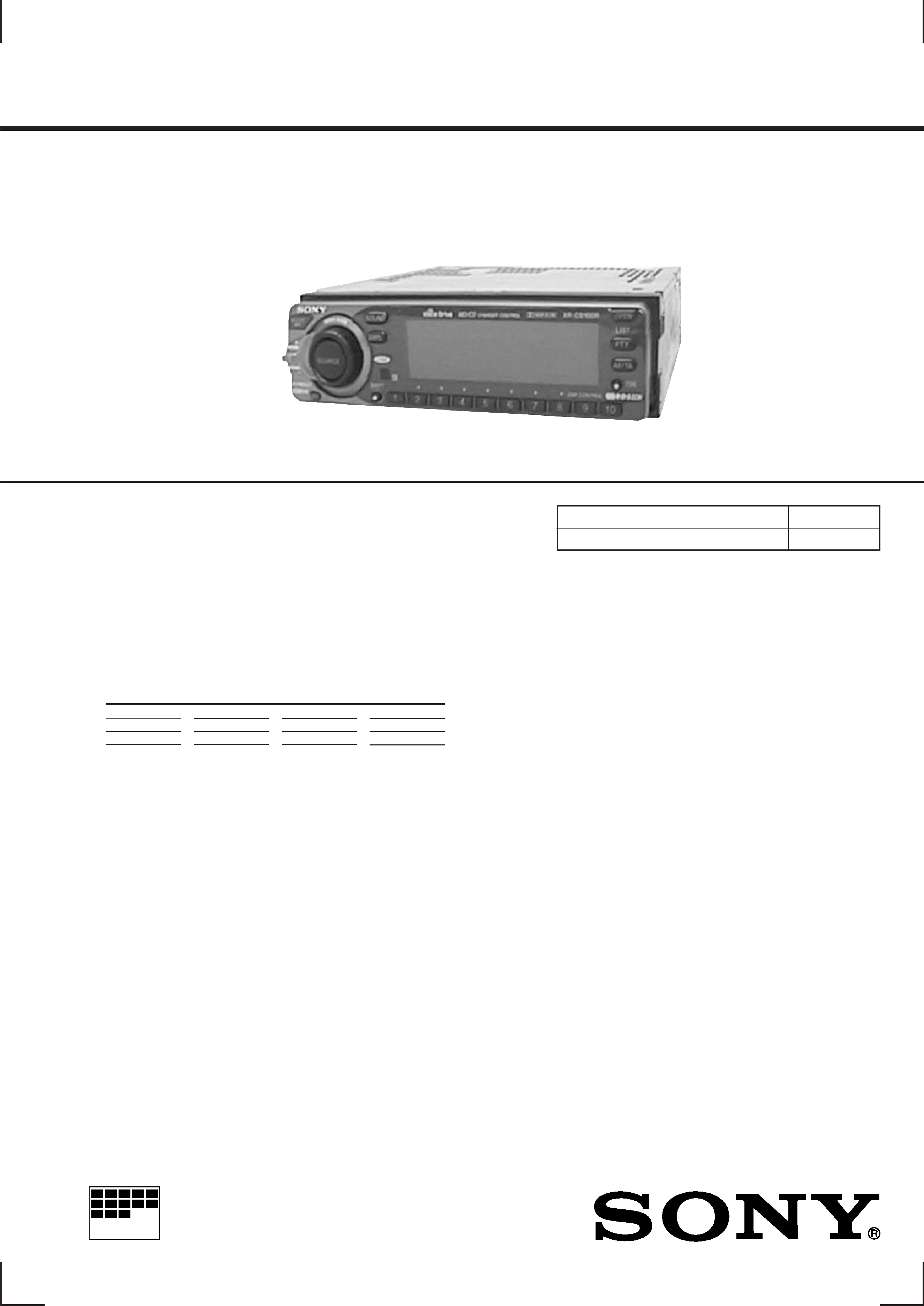
XR-C9100R
FM/MW/LW CASSETTE CAR STEREO
AEP, UK Model
FM/MW/SW CASSETTE CAR STEREO
German Model
Cassette player section
Tape track
4-track 2-channel stereo
Wow and flutter
0.08 % (WRMS)
Frequency response
30 - 20,000 Hz
Signal-to-noise ratio
Cassette type
Dolby B NR
Dolby C NR
Dolby NR off
TYPE II, IV
67 dB
73 dB
61 dB
TYPE I
64 dB
70 dB
58 dB
Tuner section
FM
Tuning range
87.5 -108.0 MHz
Antenna terminal
External antenna connector
Intermediate frequency
10.7 MHz
Usable sensitivity
8 dBf
Selectivity
75 dB at 400 kHz
Signal-to-noise ratio
65 dB (stereo),
68 dB (mono)
Harmonic distortion at 1 kHz
0.7% (stereo),
0.4% (mono)
Separation
35 dB at 1 kHz
Frequency response
30 - 15,000 Hz
MW/LW (AEP, UK model)
Tuning range
MW: 531 - 1,602 kHz
LW: 153 - 281 kHz
Aerial terminal
External aerial connector
Intermediate frequency
10.71 MHz/450 kHz
Sensitivity
MW: 30
µV
LW: 50
µV
MW/SW (German model)
Tuning range
MW: 531 - 1,602 kHz
SW: 5,950 - 6,205 kHz
Aerial terminal
External aerial connector
Intermediate frequency
10.71 MHz/450 kHz
Sensitivity
MW: 30
µV
SW: 50
µV
Power amplifier section
Outputs
Speaker outputs
(sure seal connectors)
Speaker impedance
4 - 8 ohms
Maximum power output
45 W
× 4 (at 4 ohms)
Continued on next page
SPECIFICATIONS
MICROFILM

2
TABLE OF CONTENTS
1. GENERAL
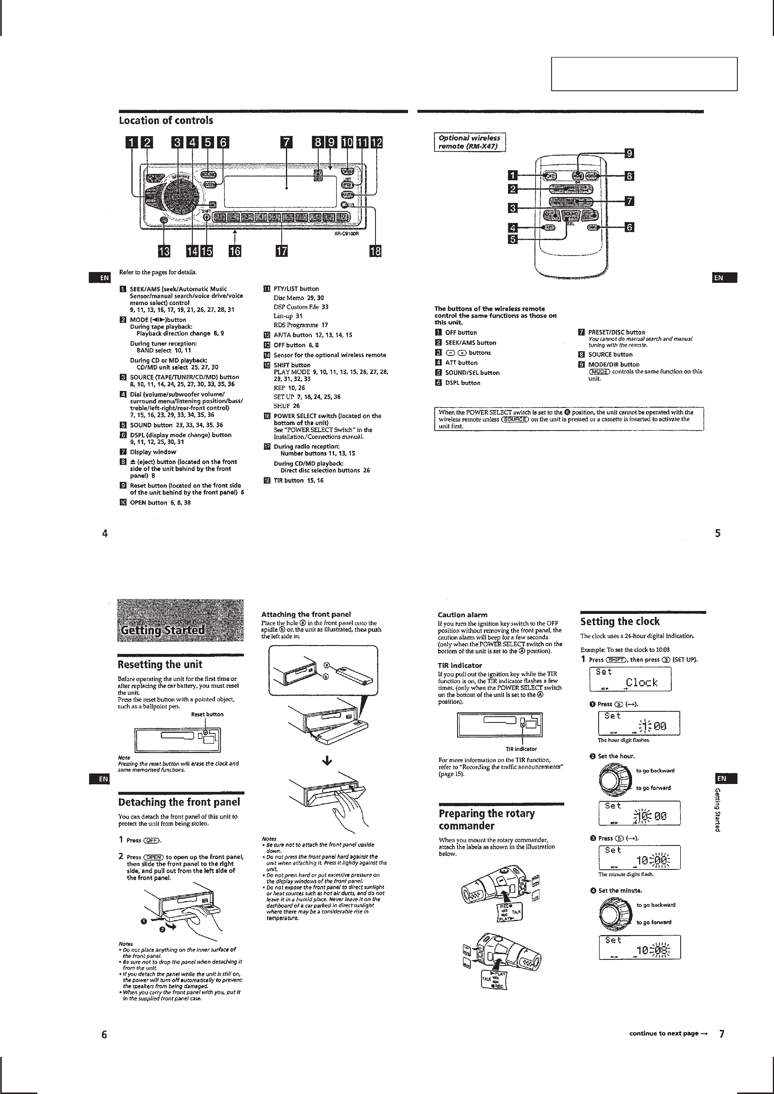
Location of Controls ............................................................... 3
Getting Started ........................................................................ 3
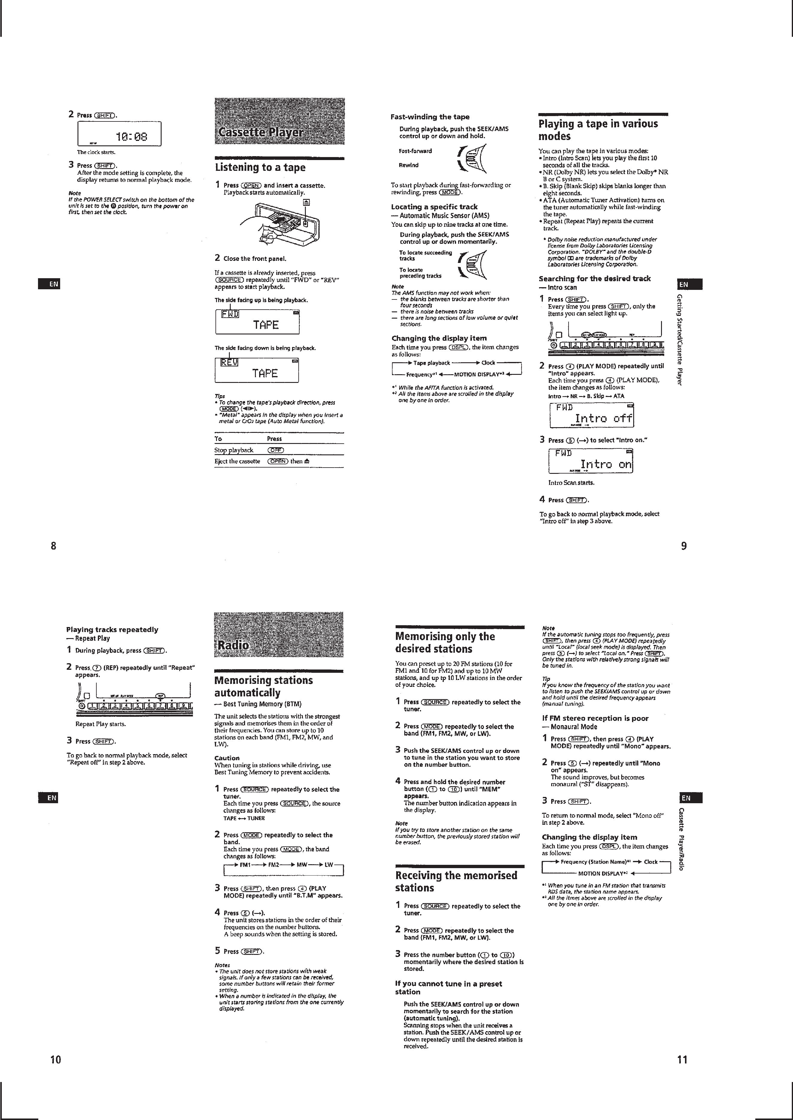
Cassette Player ....................................................................... 4
Radio ...................................................................................... 4
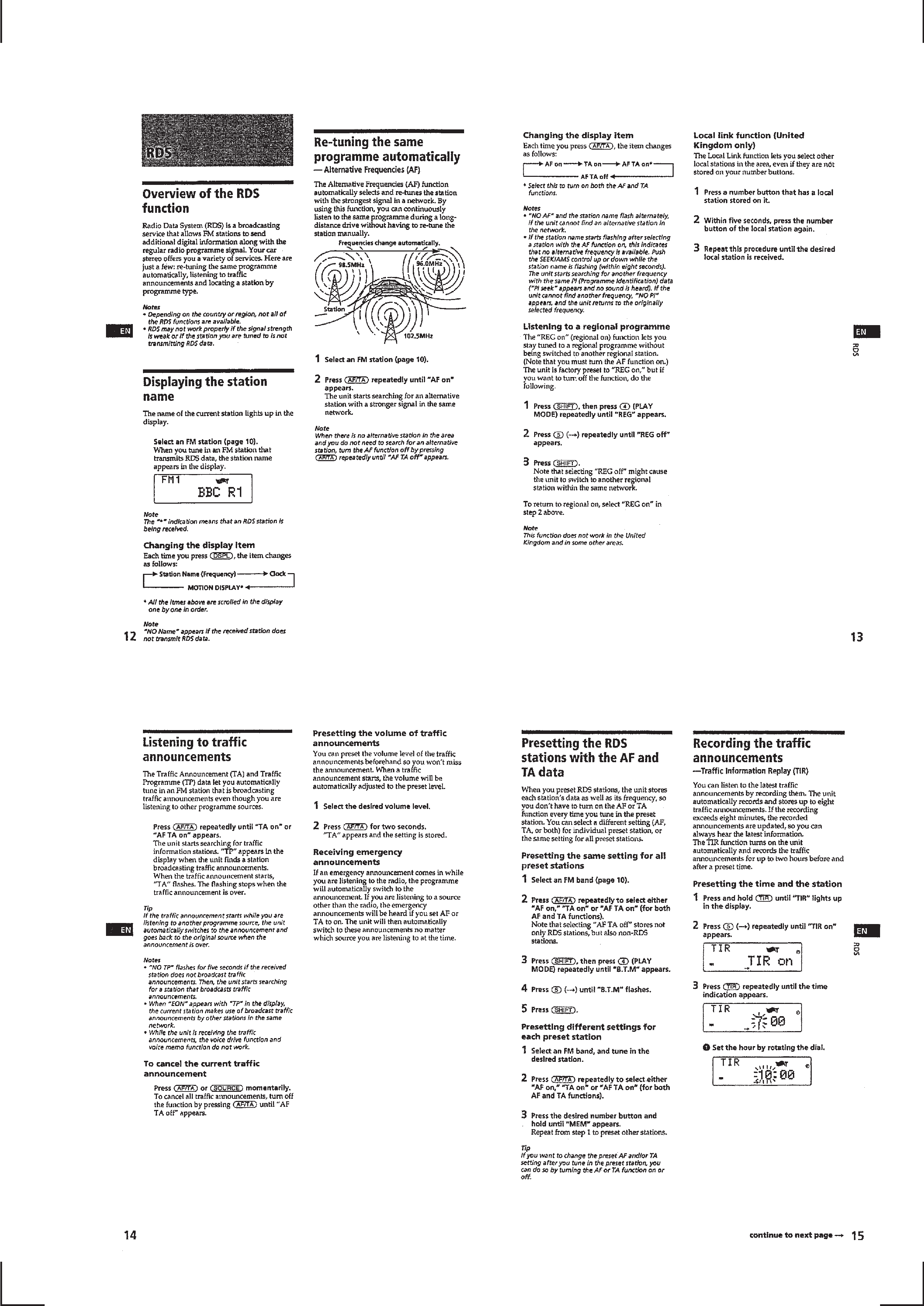
RDS ........................................................................................ 5
Voice Drive ............................................................................. 6
Voice Memo ............................................................................ 7
Other Functions ...................................................................... 7
CD/MD Unit ........................................................................... 8
DSP ....................................................................................... 10
Connections .......................................................................... 12
2. DISASSEMBLY
2-1. Cover ................................................................................ 14
2-2. Front Panel Assy .............................................................. 14
2-3. Sub Panel Assy ................................................................. 15
2-4. Mechanism Deck .............................................................. 15
2-5. Super Capacitor Board, Main Board ................................ 16
2-6. Heat Sink .......................................................................... 16
3. ASSEMBLY OF MECHANISM DECK
Housing ................................................................................ 17
Arm (Suction) ....................................................................... 17
Lever (LDG-A) / (LDG-B) ................................................... 18
Gear (Loading FT) ................................................................ 18
Guide (C) .............................................................................. 19
Mounting Position of Capstan/Reel Motor (M901) ............. 19
4. MECHANICAL ADJUSTMENTS ........................... 20
5. ELECTRICAL ADJUSTMENTS
Tape Section ......................................................................... 20
Tuner Section ........................................................................ 21
6. DIAGRAMS
6-1. Block Diagram Tape Section ....................................... 25
6-2. Block Diagram Main Section ....................................... 27
6-3. IC Pin Description ............................................................ 29
6-4. Circuit Boards Location ................................................... 32
6-5. Printed Wiring Board Main Section (Side A) .............. 33
6-6. Printed Wiring Board Main Section (Side B) .............. 35
6-7. Schematic Diagram Main Section (1/5) ....................... 37
6-8. Schematic Diagram Main Section (2/5) ....................... 39
6-9. Schematic Diagram Main Section (3/5) ....................... 41
6-10. Schematic Diagram Main Section (4/5) ....................... 43
6-11. Schematic Diagram Main Section (5/5) ....................... 45
6-12. Printed Wiring Boards Inverter/Sub Section ................ 47
6-13. Schematic Diagram Inverter/Sub Section .................... 47
6-14. Printed Wiring Board Display Section ......................... 49
6-15. Schematic Diagram Display Section ............................ 51
7. EXPLODED VIEWS
7-1. Chassis Section ................................................................ 58
7-2. Front Panel Section .......................................................... 59
7-3. Mechanism Deck Section ................................................. 60
8. ELECTRICAL PARTS LIST .................................... 61
General
Outputs
Line outputs (2)
Subwoofer output
Power antenna relay
control lead
Power amplifier control
lead
Telephone ATT control
lead
Illumination control lead
Tone controls
Bass
±8 dB at 100 Hz
Treble
±8 dB at 10 kHz
Power requirements
12 V DC car battery
(negative ground)
Dimensions
Approx. 178
× 50 × 180 mm
(w/h/d)
Mounting dimensions
Approx. 182
× 53 × 160 mm
(w/h/d)
Mass
Approx. 1.5 kg
Supplied accessories
Rotary commander RM-X4V (1)
Microphone (1)
Parts for installation and
connections (1 set)
Front panel case (1)
Design and specifications are subject to change without
notice.
Notes on Chip Component Replacement
· Never reuse a disconnected chip component.
· Notice that the minus side of a tantalum capacitor may be
damaged by heat.
Dolby noise reduction manufactured under license from Dolby Labo-
ratories Licensing Corporation.
"DOLBY" and the double-D symbol
a are trademarks of Dolby
Laboratories Licensing Corporation.
3
SECTION 1
GENERAL
This section is extracted AEP, UK
model's from instruction manual.
4
5