MICROFILM
SERVICE MANUAL
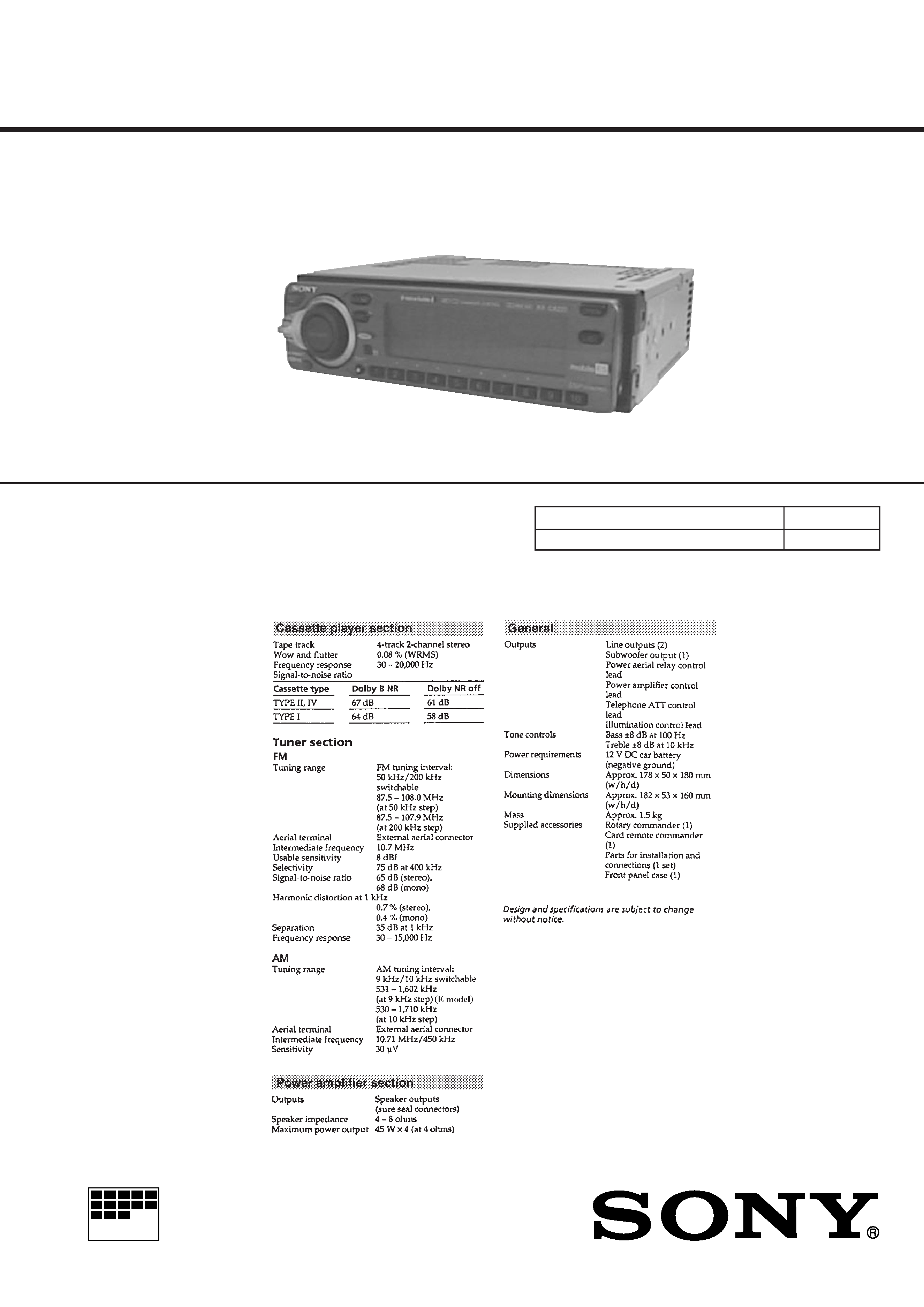
FM/AM CASSETTE CAR STEREO
US Model
E Model
SPECIFICATIONS
XR-C8220
Dolby noise reduction manufactured under license
from Dolby Laboratories Licensing Corporation.
"DOLBY" and the double-D symbol
a are trade-
marks of Dolby Laboratories Licensing Corporation.
Model Name Using Similar Mechanism
XR-C9100
Tape Transport Mechanism Type
MG-25D-136
For RM-X4S (Remote Commander),
please refer to RM-X4S Service Manual
(9-925-698-
) previously issued.

2
TABLE OF CONTENTS
1.
GENERAL
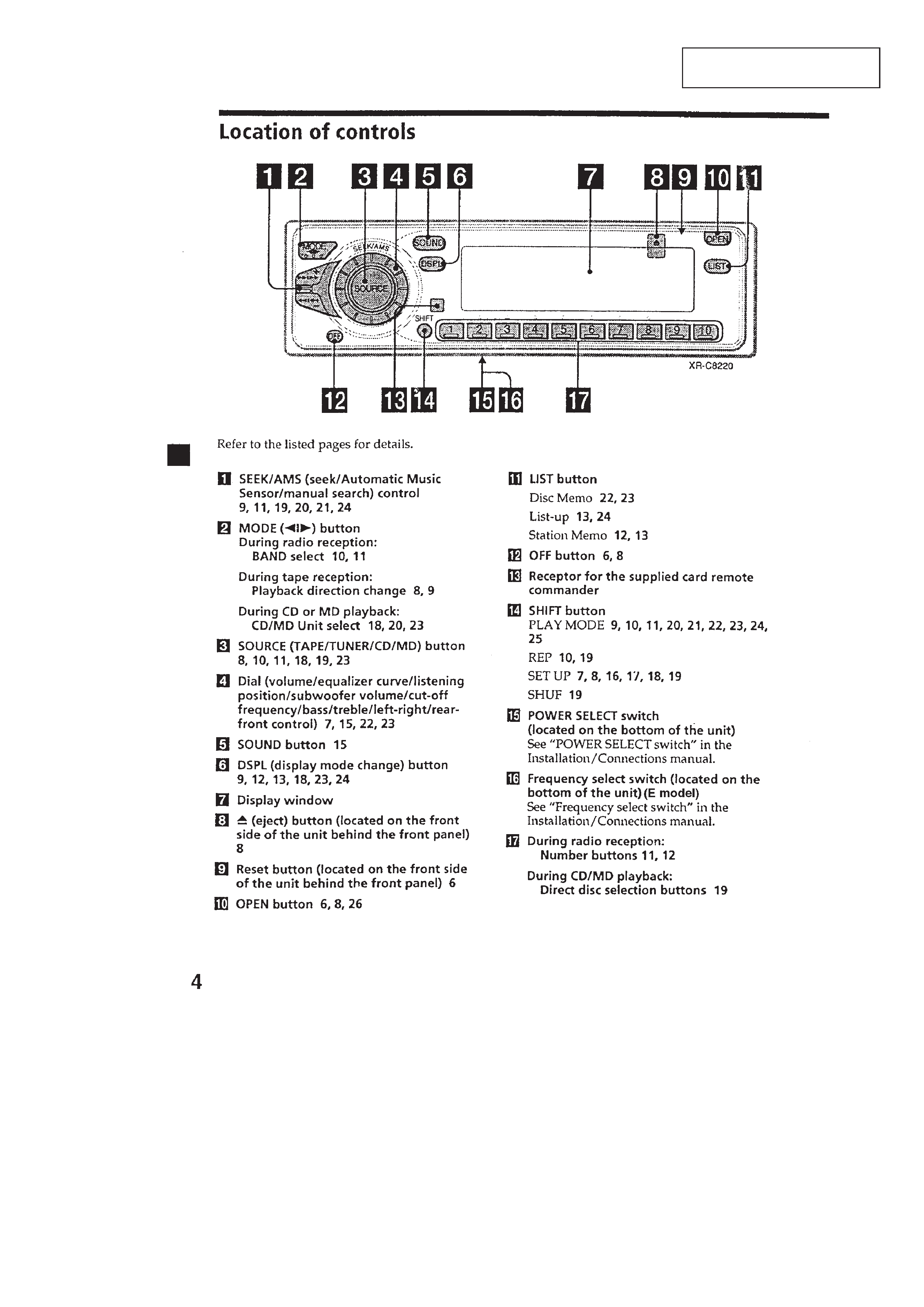
Location of controls ........................................................
3
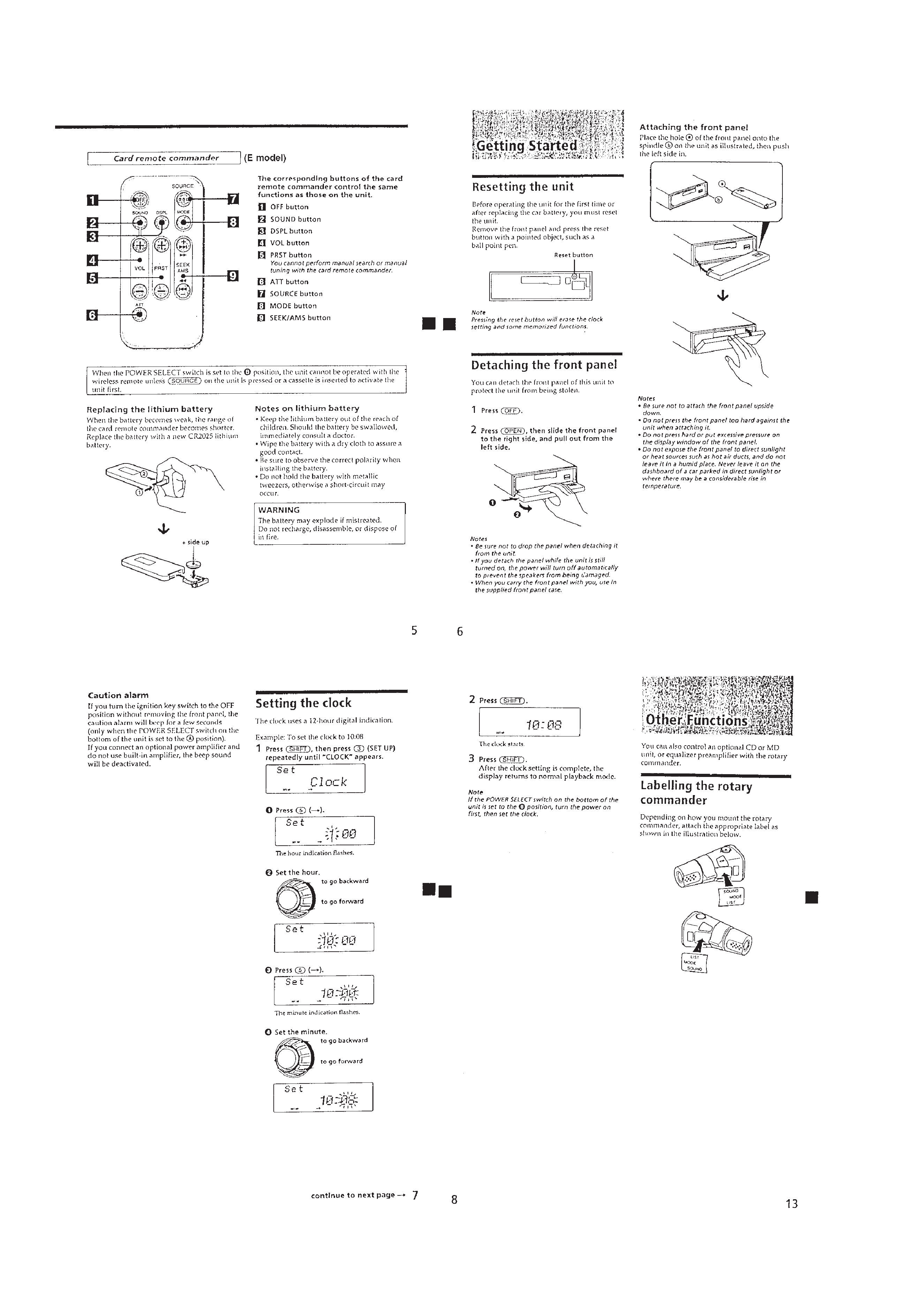
Resetting the unit ............................................................
4
Detaching the front panel ................................................
4
Setting the clock ..............................................................
4
Labelling the rotary commander .....................................
4
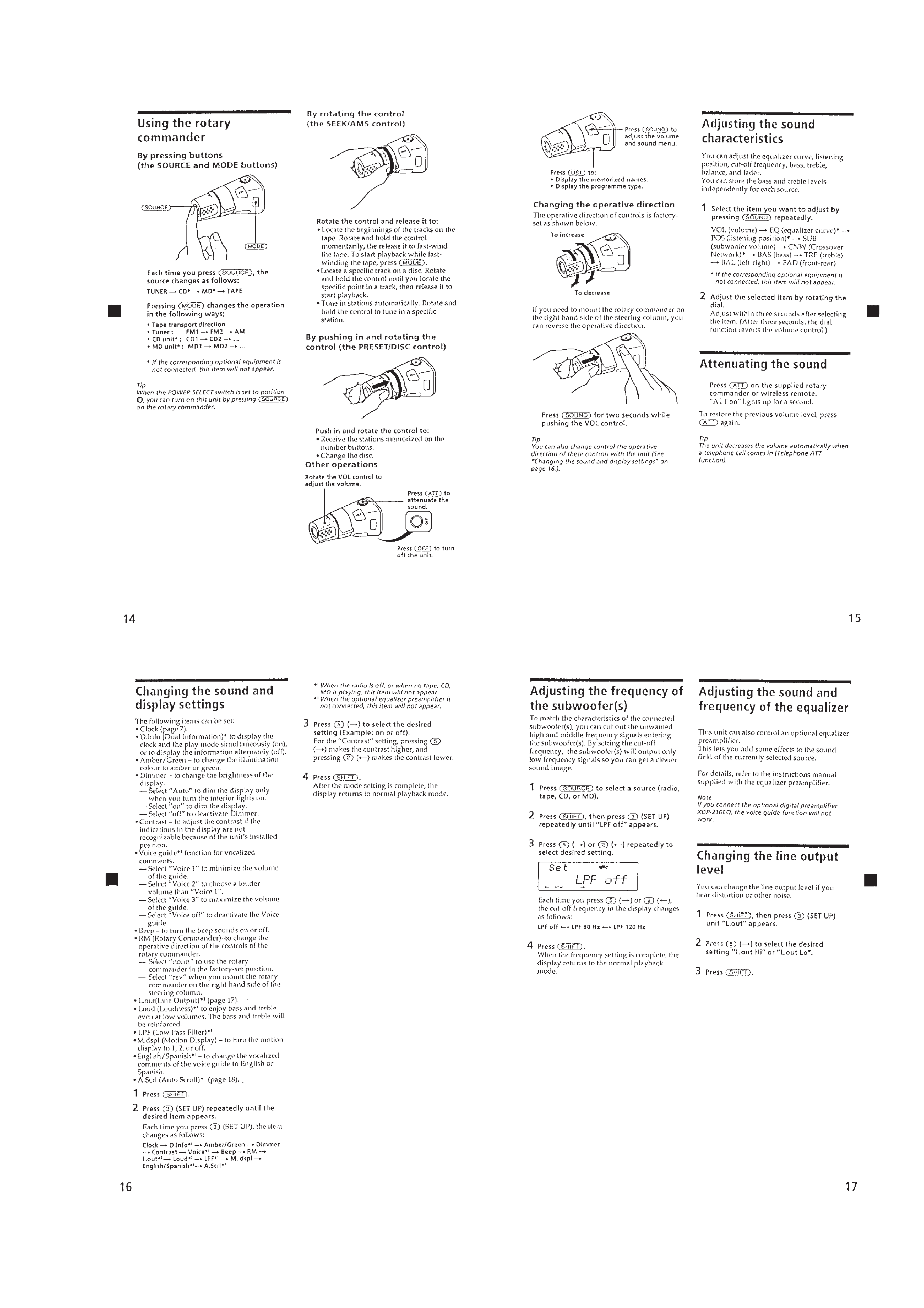
Using the rotary commander ..........................................
5
Adjusting the sound characteristics ................................
5
Attenuating the sound .....................................................
5
Changing the sound and display settings .......................
5
Adjusting the frequency of the subwoofer (S) ...............
5
Adjusting the sound and
frequency of the equalizer ..............................................
5
Changing the line output level ........................................
5
Installation .......................................................................
6
Connections .....................................................................
7
2.
DISASSEMBLY ......................................................... 9
3.
ASSEMBLY OF MECHANISM DECK ........... 11
4.
MECHANICAL ADJUSTMENTS ....................... 14
5.
ELECTRICAL ADJUSTMENTS
Test Mode ........................................................................ 14
Tape Deck Section .......................................................... 14
Tuner Section .................................................................. 15
6.
DIAGRAMS
6-1. Block Diagram TUNER/TAPE Section ................... 19
6-2. Block Diagram MAIN Section ................................. 21
6-3. Block Diagram
DISPLAY/KEY CONTROL Section ........................ 23
6-4. Block Diagram
BUS CONTROL/POWER SUPPLY Section ........... 25
6-5. Note for Printed Wiring Boards and
Schematic Diagrams ....................................................... 27
6-6. Printed Wiring Board
Main Board (Component Side) ................................ 29
6-7. Printed Wiring Board
Main Board (Conductor Side) .................................. 31
6-8. Schematic Diagram Main Section (1/4) ................... 33
6-9. Schematic Diagram Main Section (2/4) ................... 35
6-10. Schematic Diagram Main Section (3/4) ................... 37
6-11. Schematic Diagram Main Section (4/4) ................... 39
6-12. Printed Wiring Board PANEL Section .................... 41
6-13. Schematic Diagram PANEL Section ........................ 43
6-14. Printed Wiring Board
SUB/INVERTER Section ......................................... 45
6-15. Schematic Diagram SUB/INVERTER Section ........ 46
6-16. IC Pin Function Description ........................................... 50
7.
EXPLODED VIEWS ................................................ 54
8.
ELECTRICAL PARTS LIST ............................... 57
Flexible Circuit Board Repairing
· Keep the temperature of the soldering iron around 270 °C dur-
ing repairing.
· Do not touch the soldering iron on the same conductor of the
circuit board (within 3 times).
· Be careful not to apply force on the conductor when soldering
or unsoldering.
Notes on chip component replacement
· Never reuse a disconnected chip component.
· Notice that the minus side of a tantalum capacitor may be dam-
aged by heat.
3
SECTION 1
GENERAL
This section is extracted from
instruction manual.
4
5