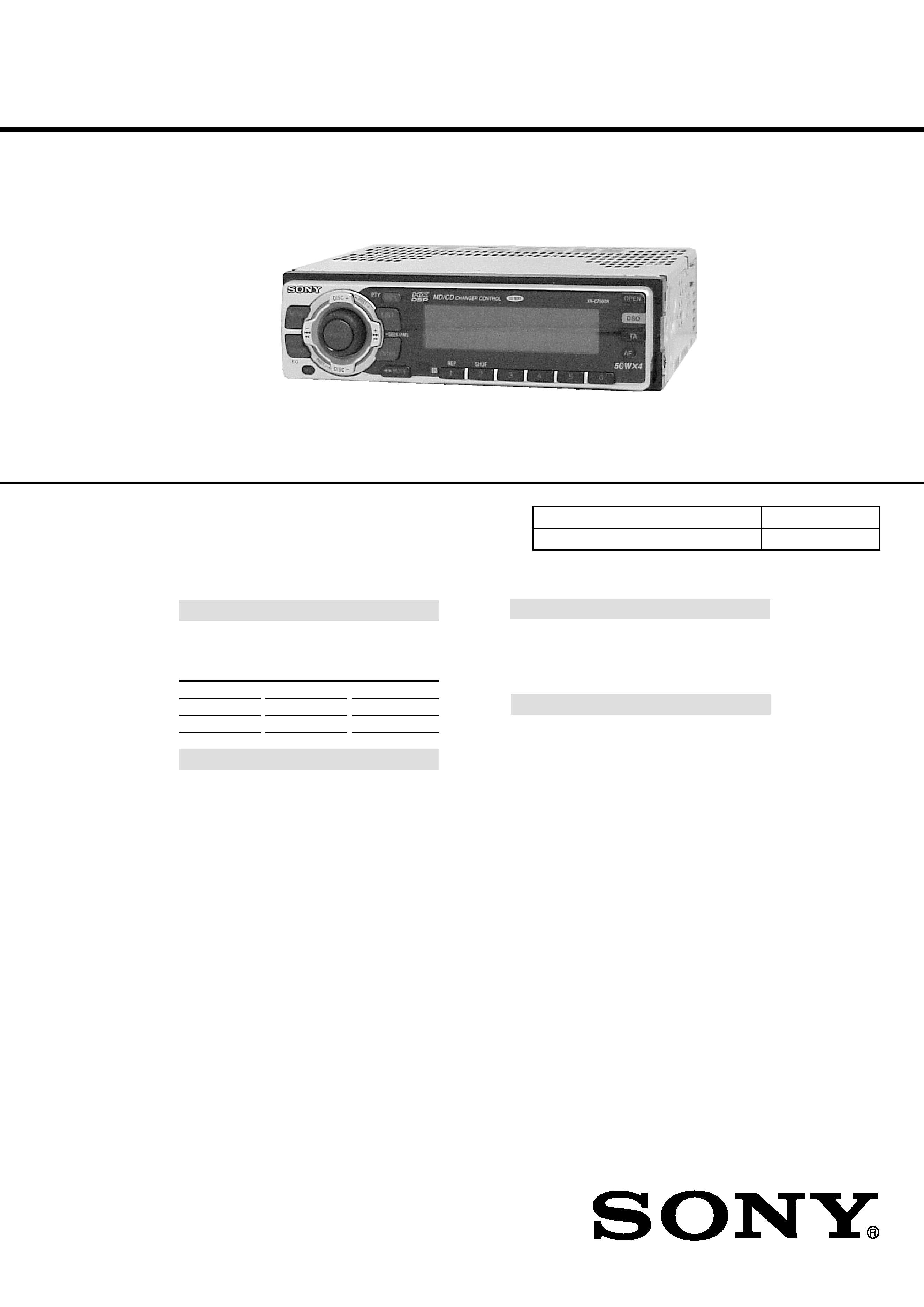
SERVICE MANUAL
FM/MW/LW CASSETTE CAR STEREO
AEP Model
UK Model
XR-C7500R/C7500RX
E Model
XR-C7500RX
Model Name Using Similar Mechanism XR-C7300/C5300R
Tape Transport Mechanism Type
MG-25G-136
SPECIFICATIONS
XR-C7500R/C7500RX
Dolby noise reduction manufactured under license
from Dolby Laboratories Licensing Corporation.
"DOLBY" and the double-D symbol ; are trade-
marks of Dolby Laboratories Licensing Corporation.
Photo: XR-C7500R
General
Outputs
Audio output
Power aerial relay control
lead
Power amplifier control
lead
Telephone ATT control
lead
Power requirements
12 V DC car battery
(negative earth)
Dimensions
Approx. 178
× 50 × 183 mm
(w/h/d)
Mounting dimensions
Approx. 182
× 53 × 162 mm
(w/h/d)
Mass
Approx. 1.2 kg
Supplied accessories
Parts for installation and
connections (1 set)
Front panel case (1)
Rotary commander
RM-X4S (XR-C7500R/
XR-C7500RX: AEP, UK)
Card remote commander
RM-X91 (XR-C7500RX: E)
Design and specifications are subject to change
without notice.
Cassette player section
Tape track
4-track 2-channel stereo
Wow and flutter
0.08 % (WRMS)
Frequency response
30 18,000 Hz
Signal-to-noise ratio
Tuner section
FM
Tuning range
87.5 108.0 MHz
Aerial terminal
External aerial connector
Intermediate frequency
10.7 MHz/450 kHz
Usable sensitivity
8 dBf
Selectivity
75 dB at 400 kHz
Signal-to-noise ratio
66 dB (stereo),
72 dB (mono)
Harmonic distortion at 1 kHz
0.6 % (stereo),
0.3 % (mono)
Separation
35 dB at 1 kHz
Frequency response
30 15,000 Hz
MW/LW
Tuning range
MW: 531 1,602 kHz
LW: 153 279 kHz
Aerial terminal
External aerial connector
Intermediate frequency
10.7 MHz/450 kHz
Sensitivity
MW: 30
µV
LW: 40
µV
Power amplifier section
Outputs
Speaker outputs
(sure seal connectors)
Speaker impedance
4 8 ohms
Maximum power output 50 W
× 4 (at 4 ohms)
Cassette type
TYPE II, IV
TYPE I
Dolby NR off
61 dB
58 dB
Dolby B NR
67 dB
64 dB
(XR-C7500R/C7500RX: AEP, UK)
For RM-X4S (Remote Commander),
please refer to RM-X4S Service Manual
(9-925-698-S) previously issued.
Ver 1.1 2001.05
9-870-124-12
Sony Corporation
2001E0500-1
e Vehicle Company
C
2001.5
Shinagawa Tec Service Manual Production Group
2
TABLE OF CONTENTS
1.
SERVICING NOTES ............................................... 2
2.
GENERAL
Location of Controls .......................................................
3
Setting the Clock .............................................................
3
Installation .......................................................................
4
Connections .....................................................................
6
3.
DISASSEMBLY ......................................................... 10
4.
ASSEMBLY OF MECHANISM DECK ........... 12
5.
MECHANICAL ADJUSTMENTS ....................... 15
6.
ELECTRICAL ADJUSTMENTS
Test Mode ........................................................................ 15
Tape Deck Section .......................................................... 16
Tuner Section .................................................................. 16
7.
DIAGRAMS
7-1. Block Diagram TUNER/TAPE Section ................... 17
7-2. Block Diagram MAIN Section ................................. 18
7-3. Block Diagram
DISPLAY/KEY CONTROL Section ........................ 19
7-4. Block Diagram
BUS CONTROL/POWER SUPPLY Section ........... 20
7-5. Note for Printed Wiring Boards and
Schematic Diagrams ....................................................... 21
7-6. Printed Wiring Board
Main Board (Component Side) ................................ 22
7-7. Printed Wiring Board
Main Board (Conductor Side) .................................. 23
7-8. Schematic Diagram Main Board (1/4) ..................... 24
7-9. Schematic Diagram Main Board (2/4) ..................... 25
7-10. Schematic Diagram Main Board (3/4) ..................... 26
7-11. Schematic Diagram Main Board (4/4) ..................... 27
7-12. Printed Wiring Board SUB Board ........................... 28
7-13. Schematic Diagram SUB Board ............................... 28
7-14. Printed Wiring Board KEY Board ........................... 30
7-15. Schematic Diagram KEY Board .............................. 31
7-16. IC Pin Function Description ........................................... 34
8.
EXPLODED VIEWS ................................................ 40
9.
ELECTRICAL PARTS LIST ............................... 43
Notes on chip component replacement
· Never reuse a disconnected chip component.
· Notice that the minus side of a tantalum capacitor may be dam-
aged by heat.
Flexible Circuit Board Repairing
· Keep the temperature of the soldering iron around 270 °C dur-
ing repairing.
· Do not touch the soldering iron on the same conductor of the
circuit board (within 3 times).
· Be careful not to apply force on the conductor when soldering
or unsoldering.
SECTION 1
SERVICING NOTES
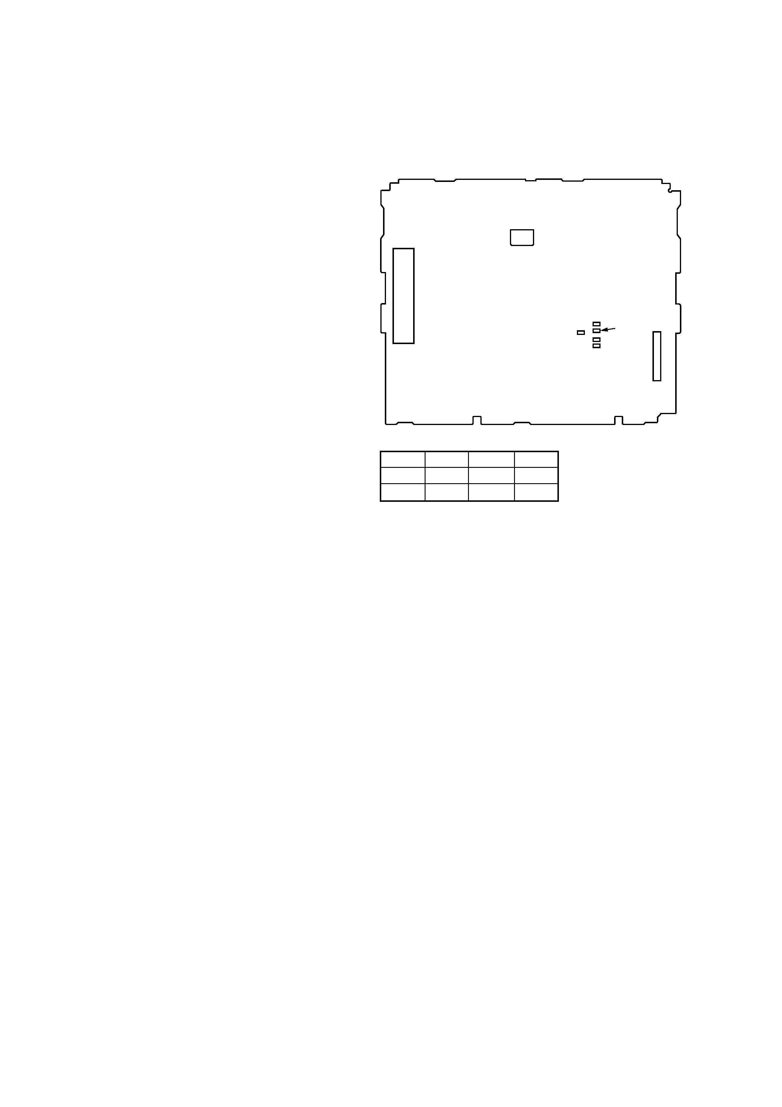
MODEL IDENTIFICATION
The XR-C7500R and XR-C7500RX have three types of MAIN
boards respectively.
TUX1
R606
R607
CN201
MAIN BOARD (Conductor Side)
TYPE A TYPE B TYPE C
R606
×
aa
R607
a
×
a
3
SECTION 2
GENERAL
This section is extracted from
instruction manual.
5
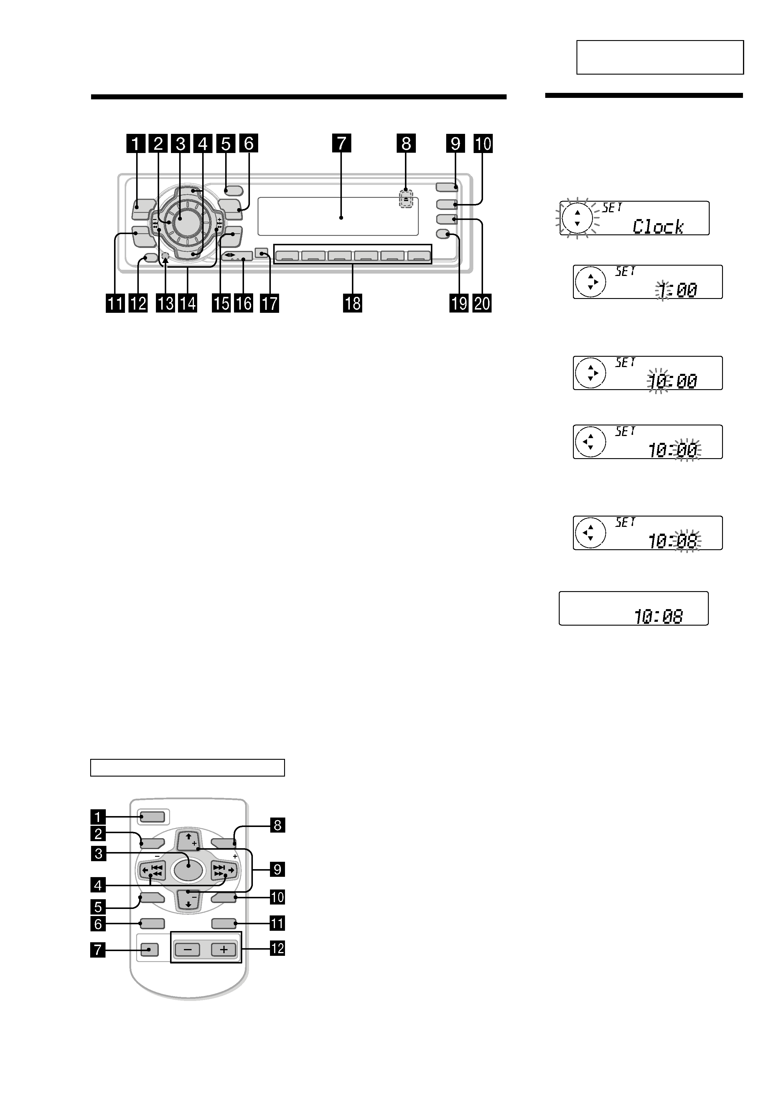
Location of controls
1 MENU button
9, 11, 12, 13, 15, 17, 18, 20, 21, 23, 24,
26, 27, 30, 31, 33, 34, 35
2 Volume control dial
3 SOURCE (TUNER/TAPE/CD/MD) button
6, 8, 10, 12, 13, 19, 20, 24, 25, 26, 27, 31,
34
4 PRST/DISC +/ (cursor up/down) buttons
8, 9, 11, 12, 13, 15, 17, 18, 19, 20, 21, 22,
23, 24, 26, 27, 30, 31, 32, 33, 34, 35
During radio reception:
Preset stations select 13
During CD/MD playback:
Disc change 32
5 DSPL/PTY (display mode change/
programme type) button
11, 18, 23, 31, 33
6 LIST button
Disc memo 33
List-up 22, 34
7 Display window
8 Z (eject) button (located on the front side
of the unit behind the front panel) 10
9 OPEN button 7, 10, 36
q; DSO button 26
qa SOUND button 24, 25, 26
qs OFF button* 6, 7, 8, 10
qd Reset button (located on the front side
of the unit behind the front panel) 7
qf SEEK/AMS /+ (cursor left/right) buttons
8, 9, 10, 11, 12, 13, 15, 17, 18, 19, 21, 23,
24, 25, 26, 27, 30, 31, 32, 33, 35
Seek 13, 15, 19
Automatic Music Sensor 10, 32
Manual search 13, 32
XR-C7500RX/XR-C7500R
D I SC +
PR
S
T+
D IS C
PR
ST-
SOURCE
DSPL
LIST
AF
OFF
PTY
ENTER
MENU
SOUND
1
2
3
4
56
-SEEK/AMS
REP
SHUF
TA
OPEN
MODE
DSO
qg ENTER button
9, 11, 12, 13, 15, 17, 18, 20, 21, 22, 23,
24, 26, 27, 30, 31, 33, 34, 35
qh MODE button 10, 11, 12, 13, 19, 20, 31,
34
During tape playback:
Playback direction change 10
During radio reception:
BAND select 12, 13
During CD/MD playback:
CD/MD unit select 31
qj Receptor for the card remote
commander
qk Number buttons
During radio reception:
Preset number select
12, 13, 16, 17, 20, 21
During tape playback:
(1) REP 11
During CD/MD playback:
(1) REP 32
(2) SHUF 32
ql AF button 15, 17
w; TA button 16, 17
* Warning when installing in a car
without ACC (accessory) position on
the ignition key switch
Be sure to press (OFF) on the unit for two
seconds to turn off the clock display after
turning off the engine.
When you press (OFF) only momentarily,
the clock display does not turn off and this
causes battery wear.
Refer to the pages listed for details.
2 Press (ENTER).
The clock starts.
After the clock setting is complete, the
display returns to normal playback mode.
Tips
· You can use the convenient CT function to set
the clock automatically (page 18).
· When the D.Info mode is set to on, the time is
always displayed (page 30).
Setting the clock
The clock uses a 24-hour digital indication.
Example: To set the clock to 10:08
1 Press (MENU), then press either side of
(PRST/DISC) repeatedly until "Clock"
appears.
1
Press (ENTER).
The hour indication flashes.
2
Press either side of (PRST/DISC) to set
the hour.
3
Press (+) side of (SEEK/AMS).
The minute indication flashes.
4
Press either side of (PRST/DISC) to set
the minute.
A unit turned off by pressing (OFF) for two seconds cannot be operated with the card remote
commander unless (SOURCE) on the unit is pressed or a casette is inserted to activate the unit first.
Card remote commander RM-X91
The corresponding buttons of the card
remote commander control the same
functions as those on this unit.
1 OFF button
2 MENU button
3 SOURCE button
4 SEEK/AMS (cursor </,) buttons
5 SOUND button
6 DSPL/PTY button
7 ATT button
8 LIST button
9 DISC/PRST (cursor M/m) buttons
q; ENTER button
qa MODE button
qs VOL buttons
OFF
SEEK
SEEK
OPEN/CLOSE
MENU
LIST
SOUND
ENTER
DISC
DISC
SOURCE
DSPL
MODE
VOL
AT T
(XR-C7500RX: E)
4
15 cm
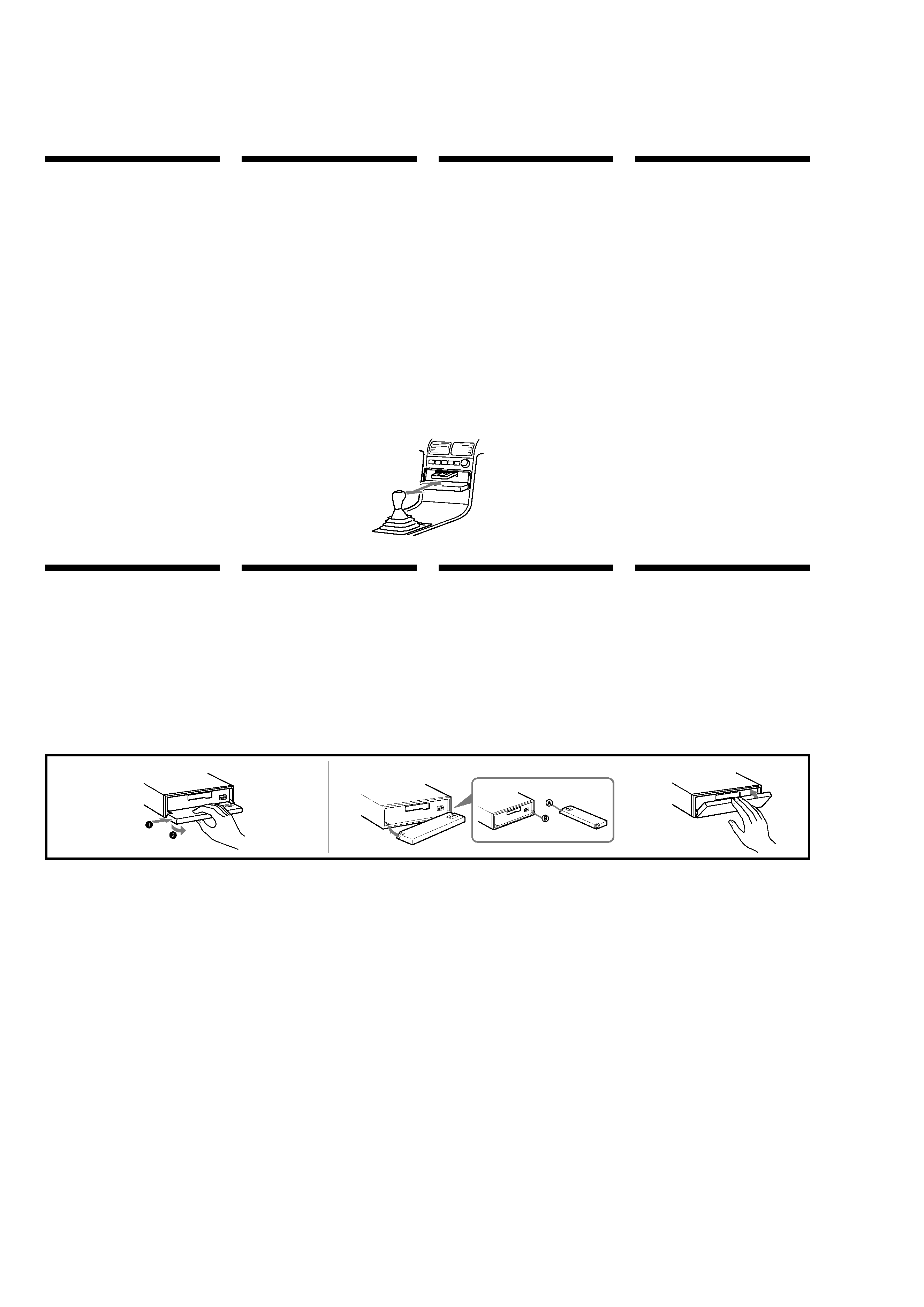
Installation
Precautions
·If you mount other Sony equipment with this
unit, it is better to mount this unit in the lower
position.
·There must be a distance of at least 15 cm
between the cassettes slot of the unit and shift
lever to insert cassette easily. Choose the
installation location carefully so the unit does
not interfere with gear shifting and other driving
operations.
·Choose the installation location carefully so that
the unit will not interfere with normal driving
operations.
·Avoid installing the unit in areas subject to dust,
dirt, excessive vibration, or high temperatures,
such as in direct sunlight or near heater ducts.
·Use only the supplied mounting hardware for a
safe and secure installation.
Mounting angle adjustment
Adjust the mounting angle to less than 20
°.
Instalación
Precauciones
·Si monta otro equipo Sony con esta unidad, es
preferible montar esta unidad en la posición más
baja.
·Para que sea posible insertar la cinta con
facilidad, debe haber una distancia de al menos
15 cm entre la ranura de inserción de cintas de la
unidad y la palanca de cambios.
Instale la unidad en un lugar que no entorpezca
las operaciones de cambio de marchas o de
conducción en general.
·Elija cuidadosamente el lugar de montaje de
forma que la unidad no dificulte las funciones
normales de conducción.
·Evite instalar la unidad donde pueda quedar
sometida a altas temperaturas, como a la luz
solar directa o al aire de calefacción, o a polvo,
suciedad o vibraciones excesivas.
·Para realizar una instalación segura y firme,
utilice solamente la ferretería de montaje
suministrada.
Ajuste del ángulo de montaje
Ajuste el ángulo de montaje a menos de 20
°.
Montering
Säkerhetsföreskrifter
·Om du monterar annan Sony-utrustning till
denna enhet är det bäst att montera denna enhet
i det undre läget.
·För att du ska kunna sätta i och ta ut bandet
måste avståndet vara minst 15 cm mellan
kassettfacket på enheten och växelspaken. När
du installerar enheten väljer du en plats så att
enheten inte är i vägen när du kör.
·Var noga när du väljer var i bilen du monterar
bilstereon, så att den inte sitter i vägen när du
kör.
·Montera inte bilstereon där den utsätts för
värme, t ex solsken eller varmluft, eller där den
utsätts för damm, smuts och/eller vibrationer.
·Använd endast de medföljande
monteringstillbehören för att vara säker på att
bilstereon monteras på ett säkert och korrekt
sätt.
Tillåten monteringsvinkel
Monteringsvinkeln får inte vara större än 20 grader.
Instalação
Precauções
·É preferível montar este aparelho na posição
mais baixa, se quiser montar simultaneamente
outros equipamentos da Sony.
·Para colocar com facilidade a cassete, deve haver
uma distância de pelo menos 15 cm entre a
ranhura de introduçäo da cassete e a alavanca
das mudanças.
Escolha o local de instalaçäo de forma a que o
aparelho näo interfira com as mudanças de
velocidade ou com as outras manobras de
conduçäo.
·Escolha com cuidado um local apropriado para
a montagem do aparelho, para que este não
interfira com as manobras necessárias à
condução do veículo.
·Evite instalar o aparelho onde possa estar sujeito
a altas temperaturas, como em locais expostos
directamente à luz do sol, ao ar quente dos
aquecimentos, ou sujeitos a pó, sujidade ou
vibração excessiva.
·Para efectuar uma instalação segura utilize
unicamente o hardware de montagem fornecido.
Ajuste do ângulo de montagem
Ajuste o ângulo de montagem a menos de 20
°.
A
How to detach and attach the
front panel
Before installing the unit, detach the front
panel.
A To detach
Before detaching the front panel, be sure to press
(OFF). Press (OPEN), then slide the front panel to
the right side, and pull out the left side.
BTo attach
Place the hole A in the front panel onto the spindle
B
on the unit as illustrated, then push the left side in.
Forma de extraer e instalar el
panel frontal
Antes de instalar la unidad, extraiga el panel
frontal.
A Para extraerlo
Antes de extraer el panel frontal, ceriórese de pulsar
(OFF). Después pulse (OPEN) para abrirlo, deslícelo
hacia la derecha, por último, tire de su parte
izquierda.
B Para instalarlo
Coloque el orificio A del panel frontal en el eje B
de la unidad, como se muestra en la ilustración, y
después presione la parte izquierda.
Ta loss/fästa frontpanelen
Ta loss frontpanelen innan du monterar
bilstereon.
A Ta loss frontpanelen
Var noga med att trycka på (OFF) innan
frontpanelen tas loss. Tryck därefter på (OPEN) för
att öppna frontpanelen. Skjut frontpanelen åt höger
och dra dess vänstra del utåt för att ta loss
frontpanelen.
B Fästa frontpanelen
Placera frontpanelen så att hålet A på frontpanelen
träs över axeln B på bilstereon enligt illustrationen.
Tryck därefter frontpanelens vänstra del inåt.
Para retirar e colocar o painel
frontal
Retire o painel frontal antes de iniciar a
instalação do aparelho.
A Para retirar
Antes de retirar o painel frontal, tem de carregar
primeiro em (OFF). A seguir, carregue em (OPEN)
para soltar o painel frontal e empurre-o para a
direita. Depois puxe o lado esquerdo do painel para
fora.
B Para colocar
Coloque o orificio A do painel frontal no eixo B do
aparelho tal como ilustrado, e depois carregue no
lado esquerdo para dentro.
B
c
5
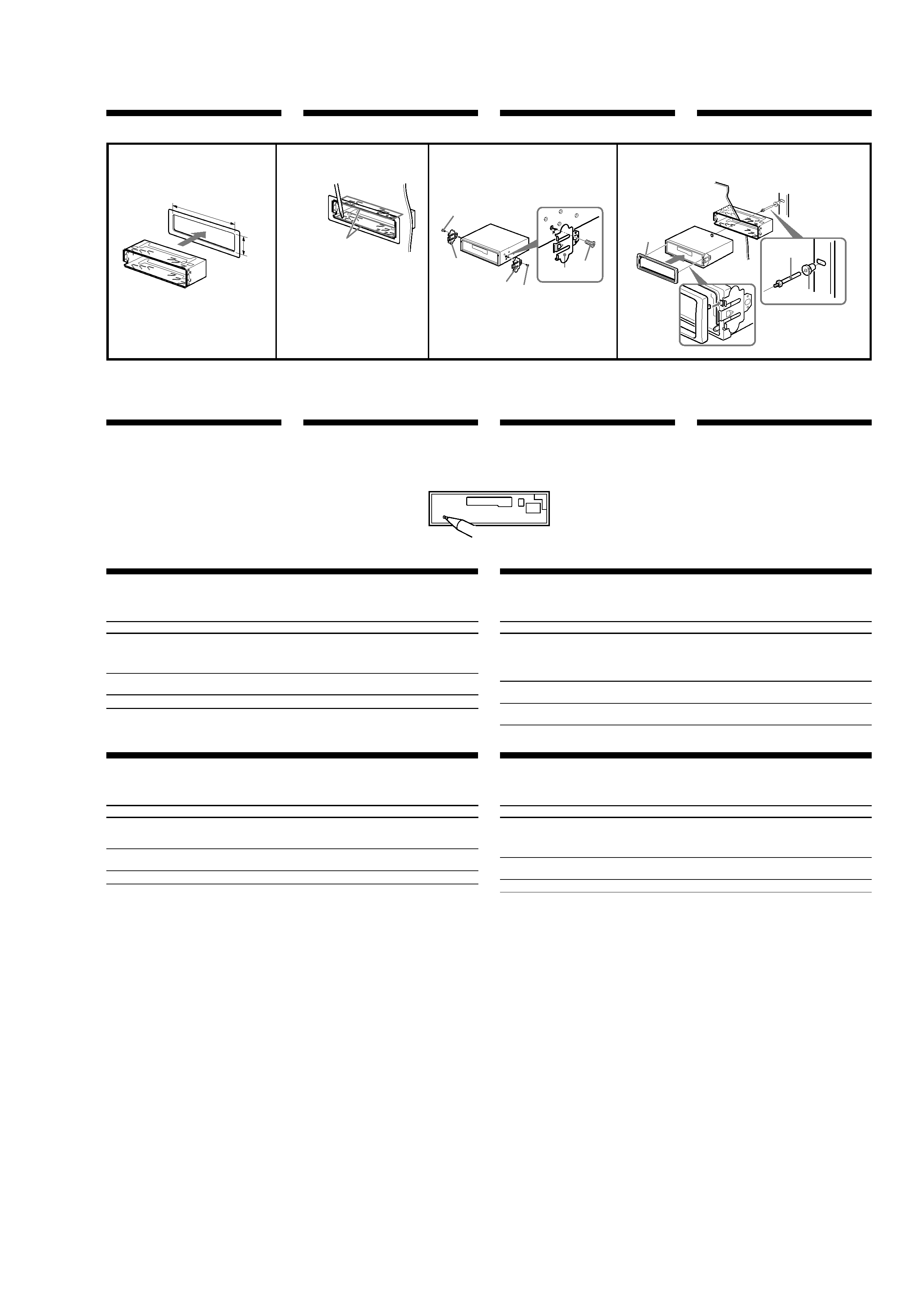
Installation in the dashboard
Instalación en el salpicadero
Montera på instrumentbrädan
Instalação no tablier
1
2
3
Fire wall
Panel cortafuegos
Brandsäker
mellanvägg
Painel corta-fogo
Dashboard
Salpicadero
Instrumentbräda
Tablier
Bend these claws outward
for a tight fit, if necessary.
Si es necesario, doble estas
uñas hacia afuera para que
encaje firmemente.
För att få en tät passning
böj dessa flikar vid behov.
Se necessário, dobre as
unhas para prender melhor.
2
3
4
4
5
7
7
5
5
7
182
mm
53 m
m
Reset button
When the installation and connections are complete,
be sure to press the reset button with a ballpoint pen,
etc.
Botón de restauración
Cuando finalice la instalación y las conexiones,
cerciórese de pulsar el botón de restauración con un
bolígrafo, etc.
Nollställningsknappen
Kom ihåg att använda en penna eller något annat
spetsigt föremål för att trycka på
nollställningsknappen när anslutningen och
monteringen är klar.
Botão de reinicialização
Quando terminar a instalação e as ligações, não se
esqueça de carregar no botão de reinicialização com a
ponta de uma caneta, esferográfica, etc.
1
1
Note
To prevent malfunction, install only with the supplied
screws 5.
Nota
Para evitar fallos de funcionamiento, realice la
instalación únicamente con los tornillos suministrados
5
.
Observera
Använd bara de medföljande skruvarna 5, så
undviker du onödiga fel.
Nota
Para evitar avarias, instale o aparelho apenas com os
parafusos fornecidos 5.
Troubleshooting guide
The following check will assist in the correction of most problems which you may encounter with your unit.
Before going through the check list below, refer to the connection and operating procedures.
Cause
Leads are not matched correctly with the car's
accessory power connector.
The car doesn't have an ACC position.
The power aerial does not have a relay box.
Problem
· Memorised stations and correct time are erased.
· The fuse has blown.
· Makes noise when the ignition key is the ON, ACC and
OFF positions.
· No power is being supplied to the unit.
· The power is continuously supplied to the unit.
The power aerial does not extend.
Felsökning
De flesta problem som kan uppstå med enheten kan åtgärdas genom att kontrollera följande. Innan du går igenom
punkterna nedan bör du läsa instruktionerna för anslutning och handhavande.
Orsak
Kablarna är inte kopplade på rätt sätt till bilens
anslutning för tillbehör.
Bilen har inte något ACC-läge.
Motorantennen har ingen relädosa.
Problem
· Minneslagrade stationer och aktuell tid har raderats.
· Säkringen har gått.
· Brus när tändningsnyckeln är i läge ON, ACC och OFF.
· Ingen ström till enheten.
· Kontinuerlig ström till enheten.
Motorantennen åker inte ut.
Guia de detecção de avarias
A verificação seguinte ajuda-o a corrigir a maioria das avarias que podem ocorrer no aparelho. Antes de utilizar a
lista de verificação abaixo, consulte as instruções de funcionamento e de ligação.
Causa
A correspondência entre os fios de ligação e o
conector de alimentação de acessórios não está
correcta.
O carro não tem posição ACC.
A antena eléctrica não tem caixa de relé.
Problema
· As estações memorizadas e a hora correcta são apagadas.
· O fusível rebentou.
· Faz ruído se a chave de ignição estiver nas posições ON,
ACC e OFF.
· O aparelho não está a receber corrente.
· O aparelho está a receber continuamente corrente.
A antena eléctrica não estica.
Guía de solución de problemas
La siguiente lista de comprobaciones le ayudará a solucionar la mayoría de los problemas que puedan surgir con
la unidad. Antes de consultar la lista, compruebe los procedimientos de conexión y funcionamiento.
Causa
Los cables no coinciden correctamente con el
conector de alimentación accesoria del automóvil.
El automóvil no dispone de posición ACC.
La antena motorizada no tiene un dispositivo de
relé.
Problema
· Se han borrado las emisoras memorizadas y la hora
correcta.
· El fusible se ha fundido.
· Se produce ruido cuando la llave de encendido se
encuentra en las posiciones ON, ACC y OFF.
· La unidad no recibe alimentación.
· La unidad recibe alimentación de forma continua.
La antena motorizada no se despliega.