MICROFILM
SERVICE MANUAL
US Model
Canadian Model
XR-C7220
E Model
XR-C7300/C7300W
Model Name Using Similar Mechanism
XR-C5100
Tape Transport Mechanism Type
MG-25G-136
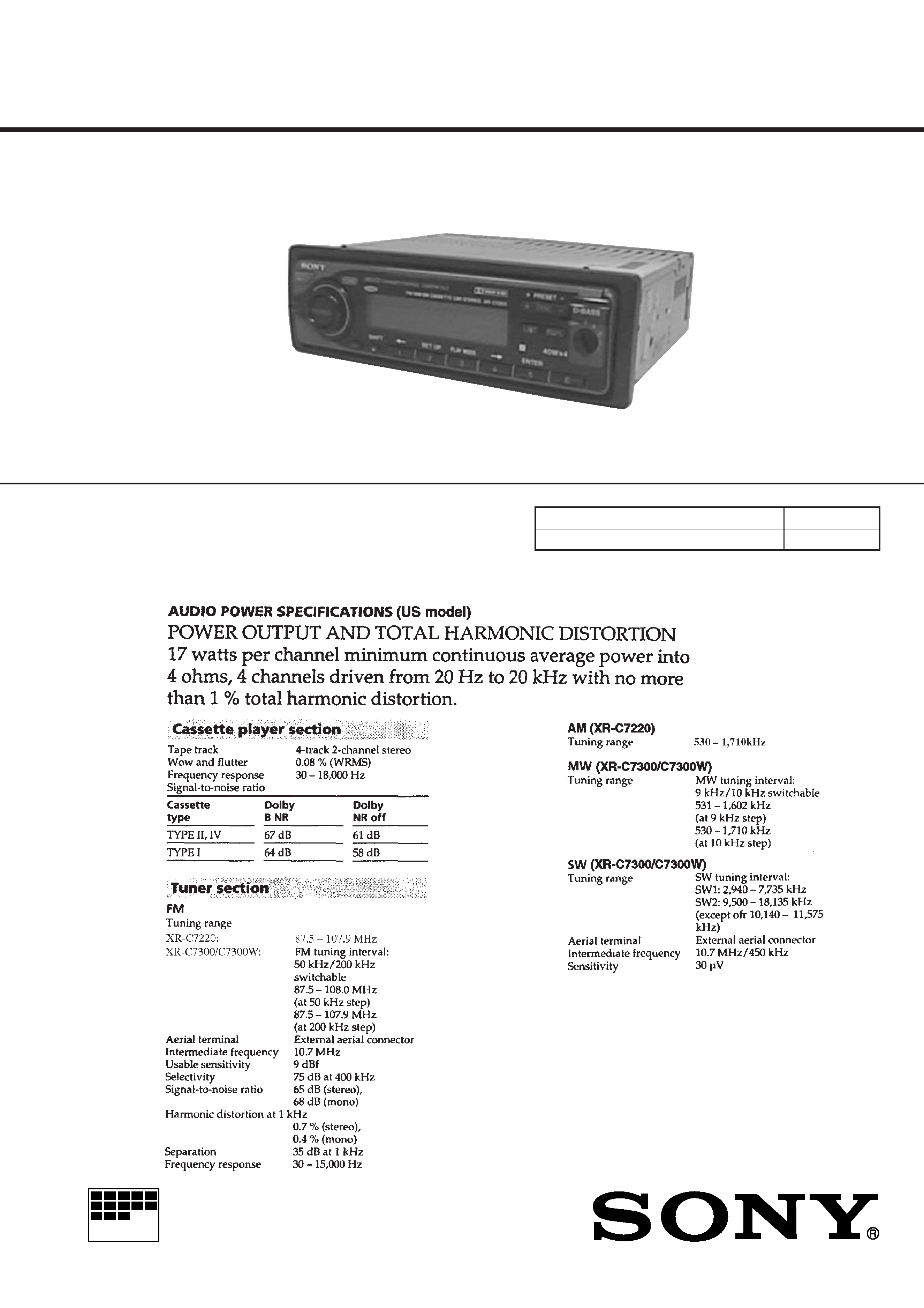
SPECIFICATIONS
XR-C7220/C7300/C7300W
For RM-X4S (Remote Commander),
please refer to RM-X4S Service Manual
(9-925-698-
) previously issued.
Continued on next page
FM/AM (MW/SW)
CASSETTE CAR STEREO
Photo: XR-C7300
Dolby noise reduction manufactured under license
from Dolby Laboratories Licensing Corporation.
"DOLBY" and the double-D symbol
a are trademarks
of Dolby Laboratories Licensing Corporation.
2
TABLE OF CONTENTS
1.
GENERAL
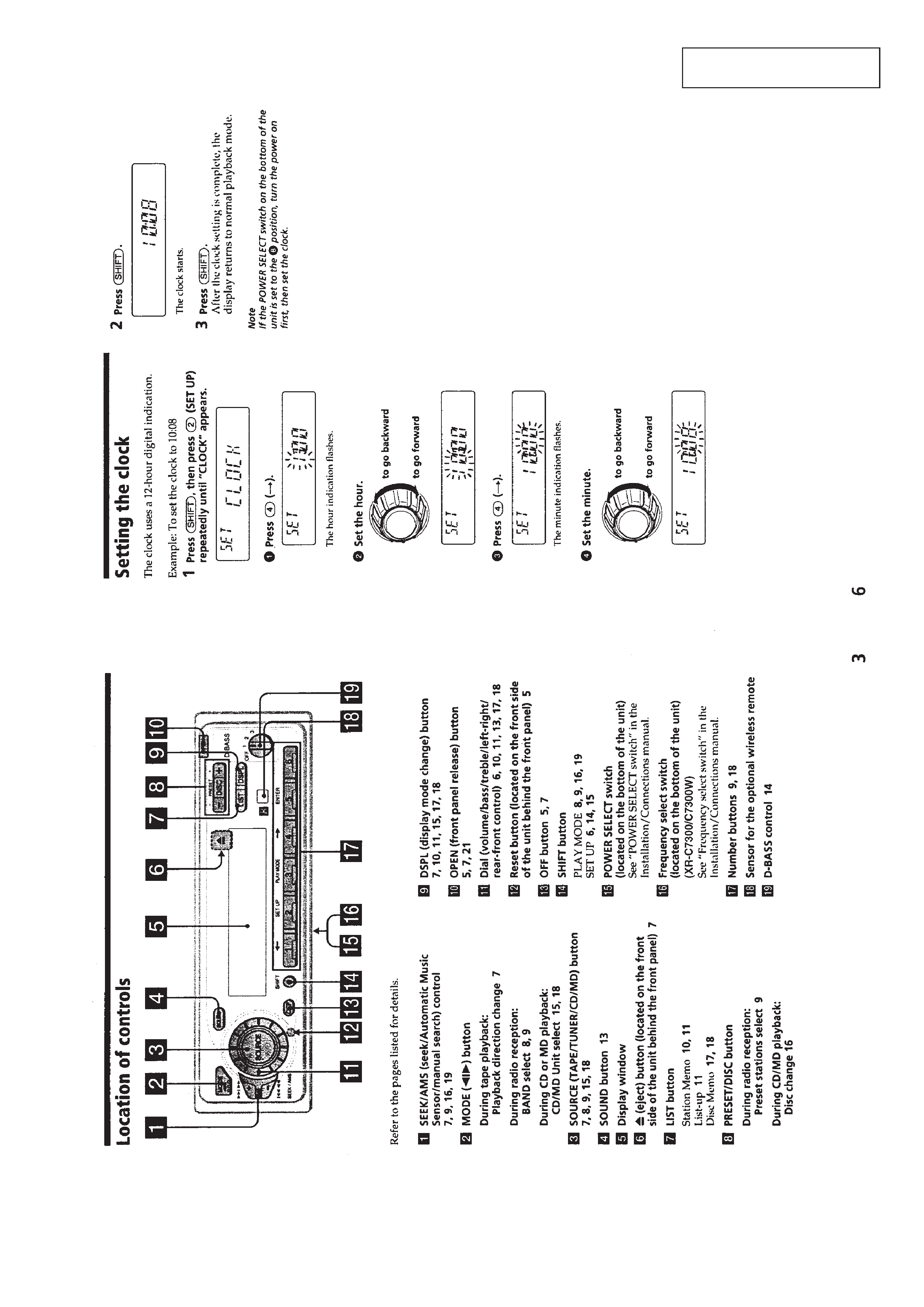
Location of Controls .......................................................
3
Setting the Clock .............................................................
3
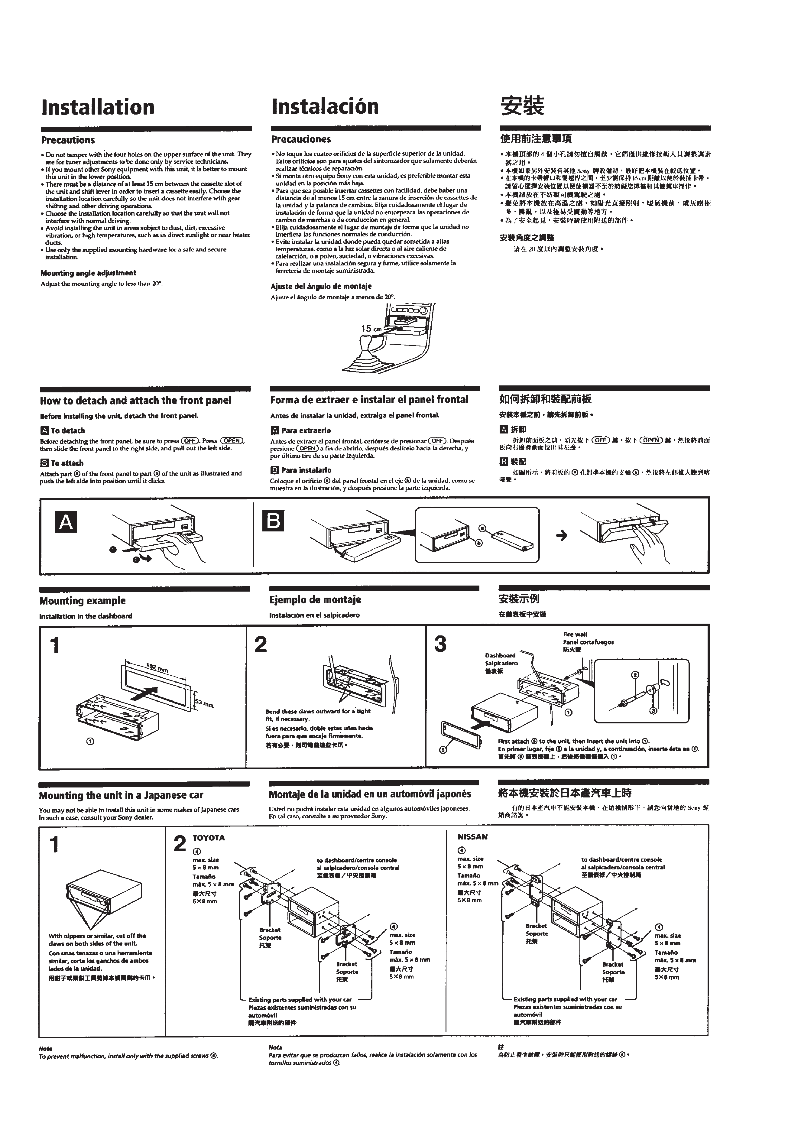
Installation .......................................................................
4
Connections .....................................................................
6
2.
DISASSEMBLY ......................................................... 8
3.
ASSEMBLY OF MECHANISM DECK ........... 10
4.
MECHANICAL ADJUSTMENTS ....................... 13
5.
ELECTRICAL ADJUSTMENTS
Test Mode ........................................................................ 13
Tape Deck Section .......................................................... 13
Tuner Section .................................................................. 14
6.
DIAGRAMS
6-1. Note for Printed Wiring Boards and
Schematic Diagrams ....................................................... 17
6-2. Schematic Diagram MAIN Section (1/3) ................. 19
6-3. Schematic Diagram MAIN Section (2/3) ................. 21
6-4. Schematic Diagram MAIN Section (3/3) ................. 23
6-5. Printed Wiring Board
MAIN Board (Component Side) .............................. 25
6-6. Printed Wiring Board
MAIN Board (Conductor Side) ................................ 27
6-7. Printed Wiring Boards PANEL Section ................... 29
6-8. Schematic Diagram PANEL Section ........................ 31
6-9. IC Pin Function Description ........................................... 35
7.
EXPLODED VIEWS ................................................ 39
8.
ELECTRICAL PARTS LIST ............................... 42
Flexible Circuit Board Repairing
· Keep the temperature of the soldering iron around 270 °C dur-
ing repairing.
· Do not touch the soldering iron on the same conductor of the
circuit board (within 3 times).
· Be careful not to apply force on the conductor when soldering
or unsoldering.
Notes on chip component replacement
· Never reuse a disconnected chip component.
· Notice that the minus side of a tantalum capacitor may be dam-
aged by heat.
3
SECTION
1
GENERAL
This
section
is
e
xtr
acted
from
instruction
manual.
4
5