MICROFILM
XR-C6090
E Model
SERVICE MANUAL
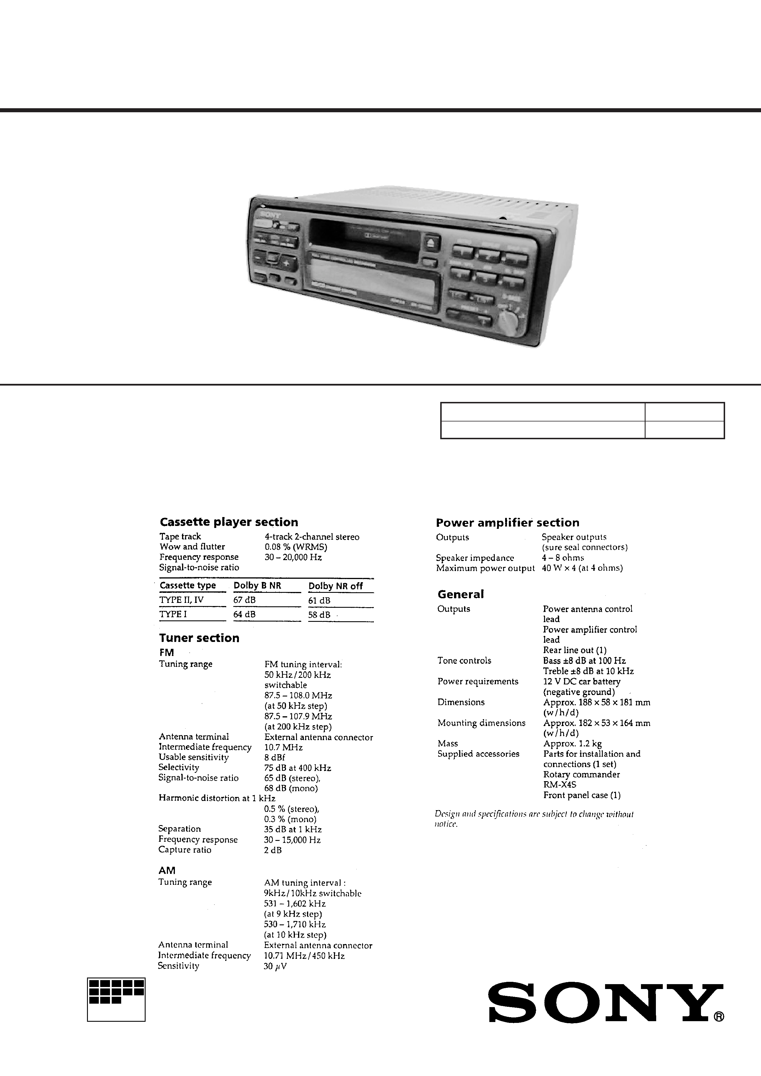
FM/AM CASSETTE CAR STEREO
SPECIFICATIONS
Model Name Using Similar Mechanism
XR-C450
Tape Transport Mechanism Type
MG-25J-136
Dolby noise reduction manufactured under license
from Dolby Laboratories Licensing Corporation.
"DOLBY" and the double-D symbol
a are trade-
marks of Dolby Laboratories Licensing Corporation.
Photo: XR-5800R
For RM-X4S (Remote Commander),
please refer to RM-X4S Service Manual
(9-925-698-
) previously issued.

2
TABLE OF CONTENTS
1.
GENERAL
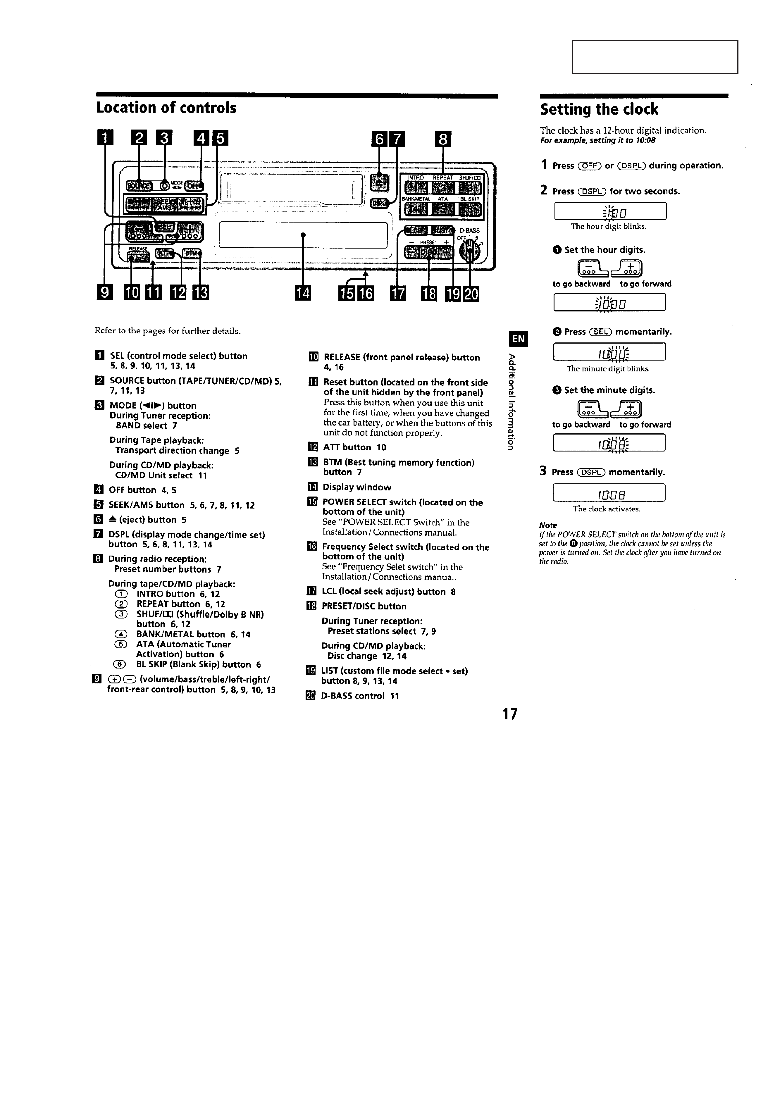
Location of Controls ....................................................... 3
Setting the Clock ............................................................. 3
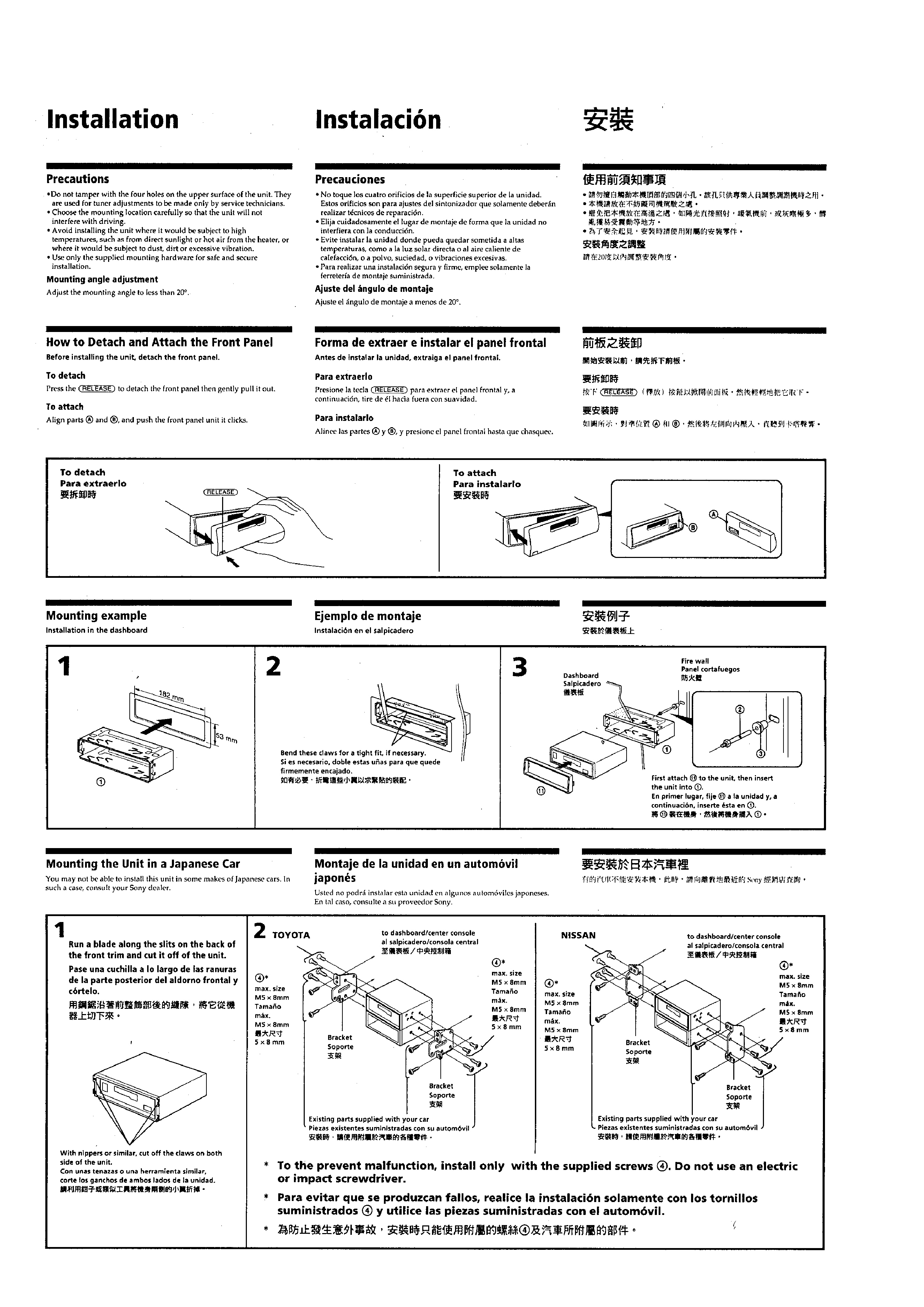
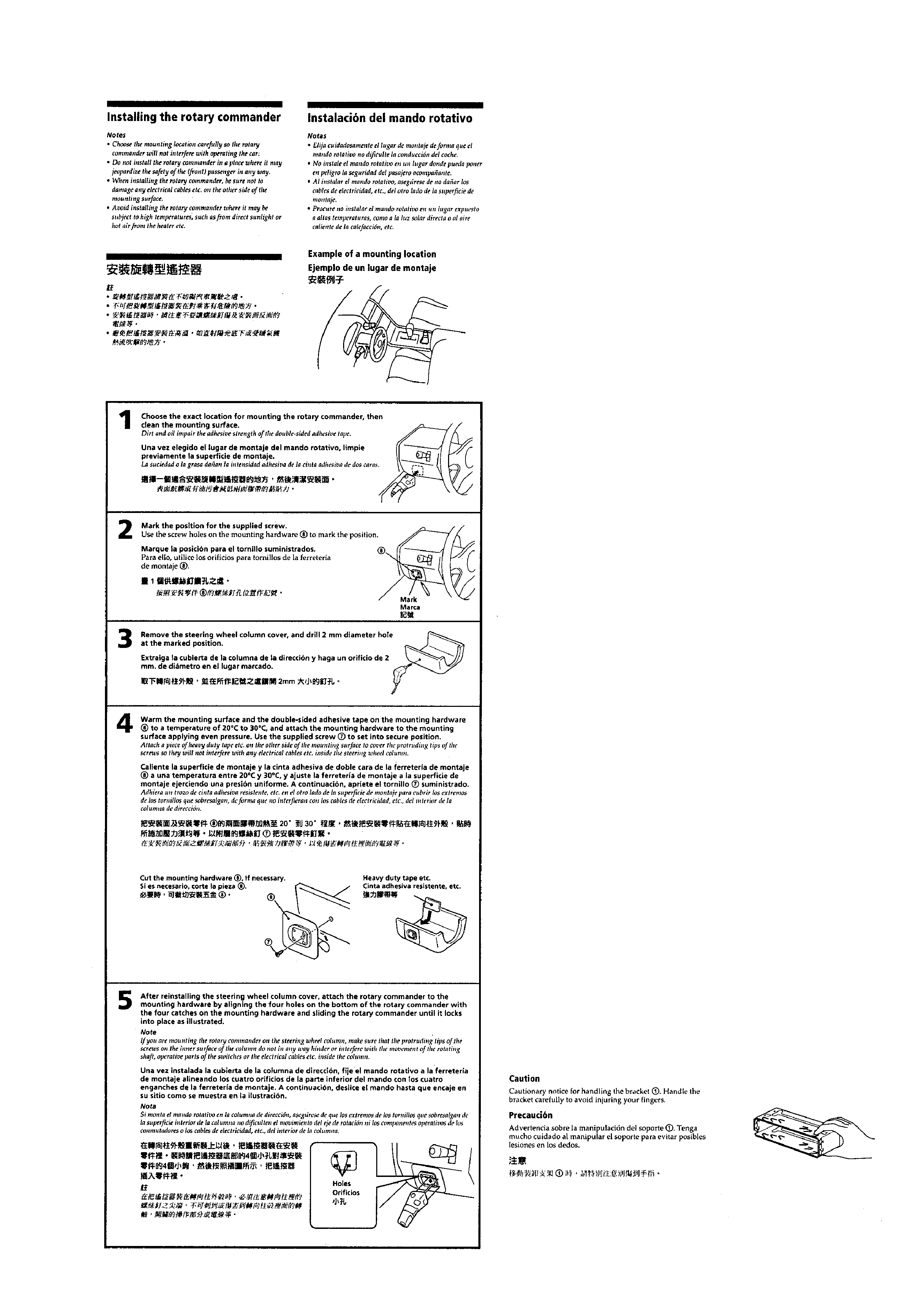
Installation ....................................................................... 4
Connection ...................................................................... 6
2.
DISASSEMBLY ......................................................... 8
3.
ASSEMBLY OF MECHANISM DECK ........... 10
4.
MECHANICAL ADJUSTMENTS ....................... 13
5.
ELECTRICAL ADJUSTMENTS
Tape Deck Section .......................................................... 13
Tuner Section .................................................................. 13
6.
DIAGRAMS
6-1. Printed Wiring Board Main Section ........................ 15
6-2. Schematic Diagram Main Section ............................ 17
6-3. Printed Wiring Board Panel Section ........................ 21
6-4. Schematic Diagram Panel Section .......................... 23
6-5. IC Pin Function Description ........................................... 27
7.
EXPLODED VIEWS ................................................ 30
8.
ELECTRICAL PARTS LIST ............................... 33
Flexible Circuit Board Repairing
· Keep the temperature of the soldering iron around 270 °C dur-
ing repairing.
· Do not touch the soldering iron on the same conductor of the
circuit board (within 3 times).
· Be careful not to apply force on the conductor when soldering
or unsoldering.
Notes on chip component replacement
· Never reuse a disconnected chip component.
· Notice that the minus side of a tantalum capacitor may be dam-
aged by heat.
3
SECTION 1
GENERAL
This section is extracted from
instruction manual.
4
5