MICROFILM
XR-C550RDS
AEP Model
UK Model
SERVICEMANUAL
FM/MW/LWCASSETTECARSTEREO
SPECIFICATIONS
Model Name Using Similar Mechanism
NEW
Tape Transport Mechanism Type
MG-25B-136
For RM-X2S (Remote Commander),
please refer to RM-X2S/X3S Service
Manual (9-960-039-
) previously issued.
Dolby noise reduction manufactured under license
from Dolby Laboratories Licensing Corporation.
"DOLBY" and the double-D symbol
aare trademarks
of Dolby Laboratories Licensing Corporation.

2
TABLE OF CONTENTS
1.
GENERAL
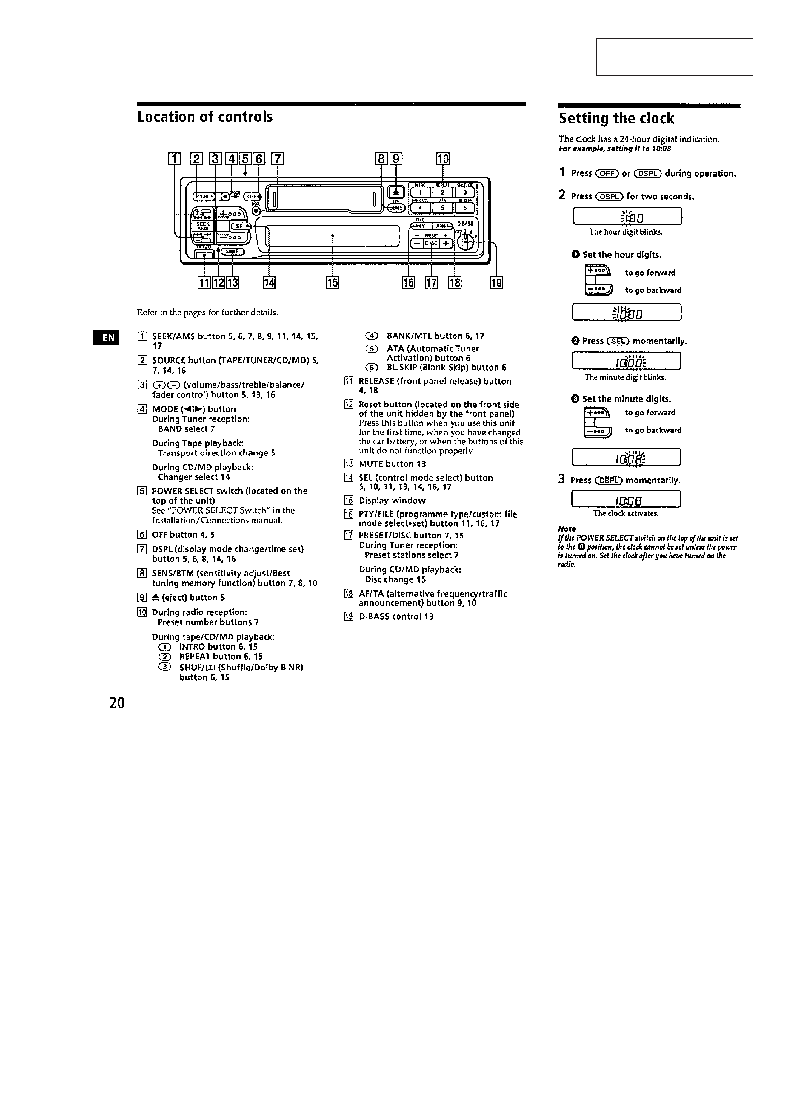
Location of Controls ........................................................ 3
Setting the Clock ............................................................. 3
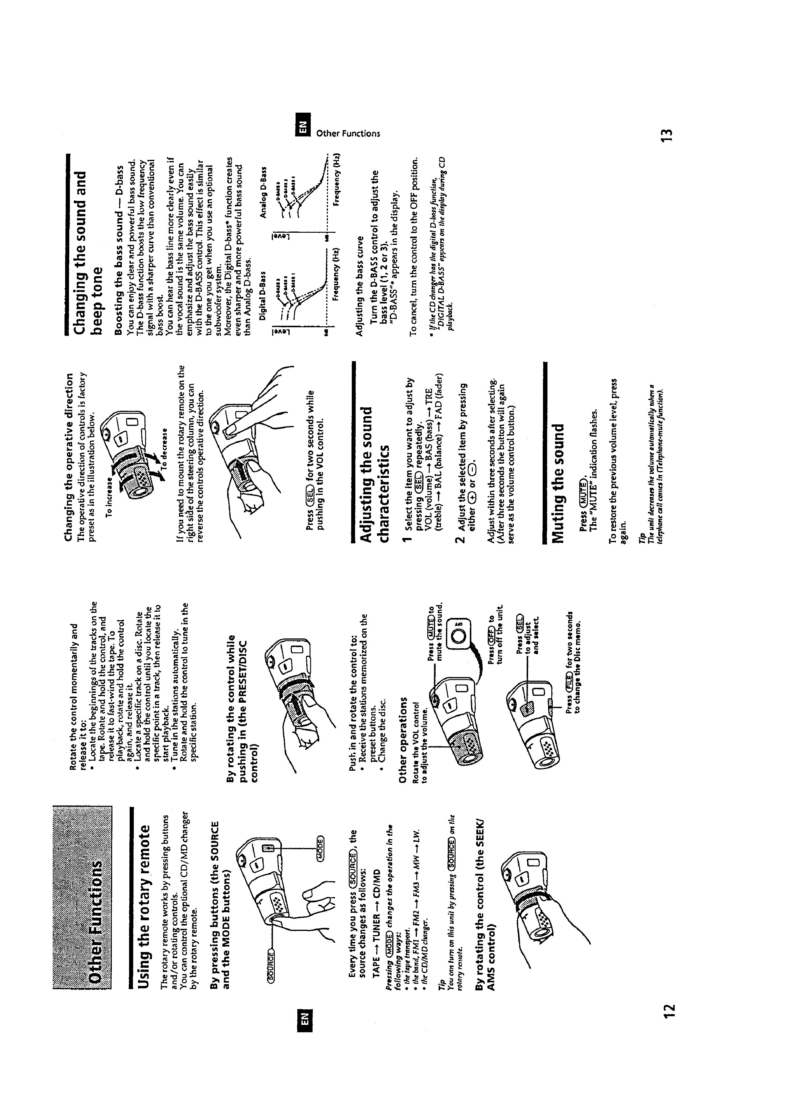
Using the Rotary Remote ................................................ 4
Adjusting the Sound Characteristics ............................... 4
Muting the Sound ............................................................ 4
Changing the Sound and Beep Tone ................................ 4
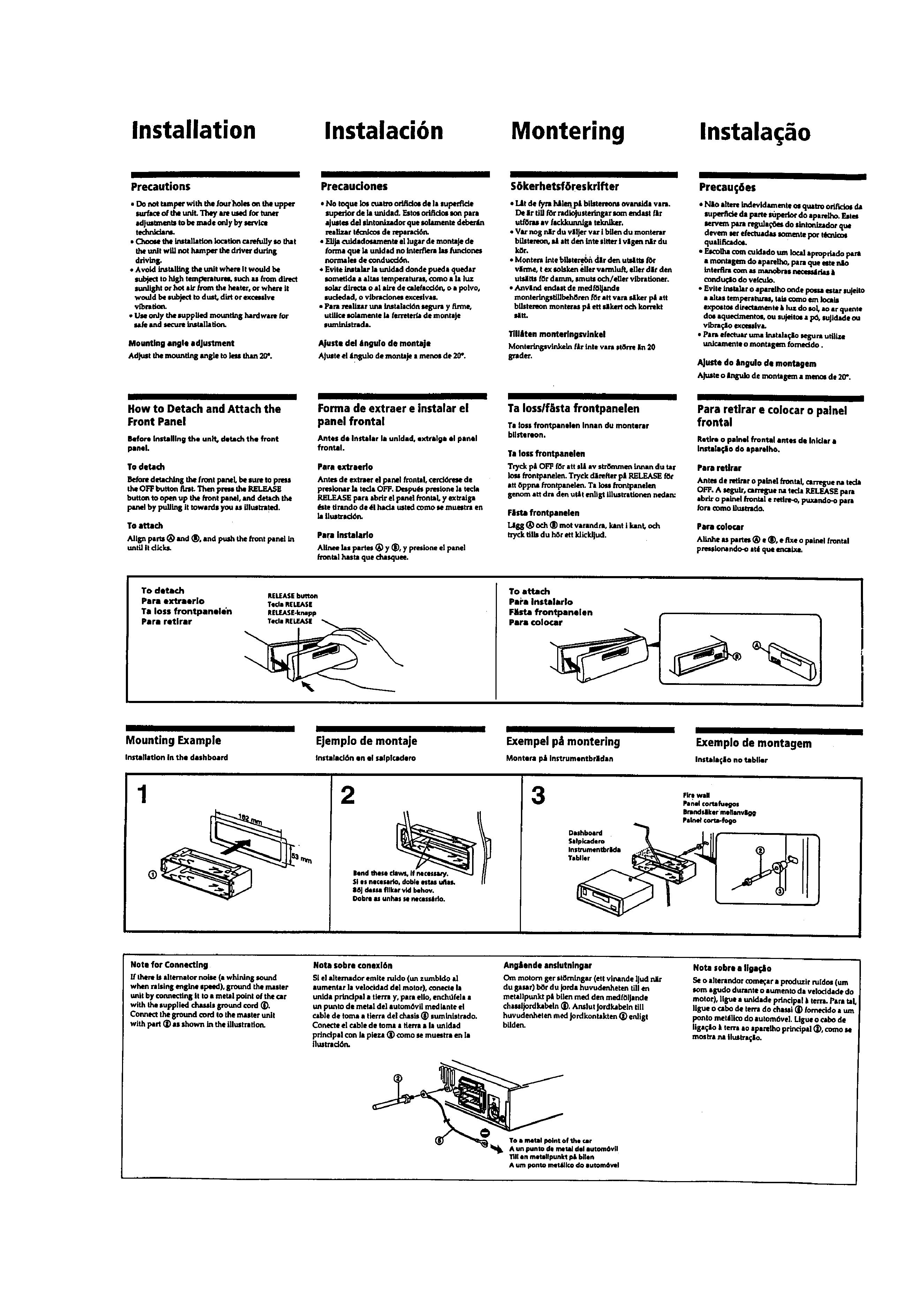
Installation ....................................................................... 5
Connections ..................................................................... 6
2.
DISASSEMBLY .......................................................... 9
3.
ASSEMBLY OF MECHANISM DECK ........... 11
4.
MECHANICAL ADJUSTMENTS ....................... 14
5.
ELECTRICAL ADJUSTMENTS
Test Mode ........................................................................ 14
Tape Deck Section ........................................................... 15
Tuner Section ................................................................... 15
6.
DIAGRAMS
6-1. Printed Wiring Boards Main Section ........................ 22
6-2. Schematic Diagram Main Section ............................. 25
6-3. Printed Wiring Board Display Section ..................... 30
6-4. Schematic Diagram Display Section ........................ 32
6-5. IC Pin Function Description ............................................ 35
7.
EXPLODED VIEWS ................................................ 37
8.
ELECTRICAL PARTS LIST ................................ 40
SERVICING NOTES
Flexible Circuit Board Repairing
· Keep the temperature of the soldering iron around 270 ° C dur-
ing repairing.
· Do not touch the soldering iron on the same conductor of the
circuit board (within 3 times).
· Be careful not to apply force on the conductor when soldering
or unsoldering
Notes on chip component replacement
· Never reuse a disconnected chip component.
· Notice that the minus side of a tantalum capacitor may be dam-
aged by heat.
3
SECTION 1
GENERAL
This section is extracted
from instruction manual.
4
5