Model Name Using Similar Mechanism
NEW
Tape Transport Mechanism Type
MG-25C-136
US Model
Canadian Model
XR-C450
E Model
XR-C440/C450
SERVICE MANUAL
XR-C440/C450
SPECIFICATIONS
Cassette player section
Tape track
4-track 2-channel stereo
Wow and flutter
0.08% (WRMS)
Frequency response
30 18,000 Hz (C440/C450: US, Canadian)
30 20,000 Hz (C450: E, Saudi Arabia)
Signal-to-noise ratio
Antenna terminal
External antenna connector
Intermediate frequency 10.7 MHz
Usable sensitivity
8 dBf
Selectivity
75 dB at 400 kHz
Signal-to-noise ratio
65 dB (stereo),
68 dB (mono)
Harmonic distortion at 1 kHz
0.5% (stereo),
0.3% (mono)
Separation
35 dB at 1 kHz
Frequency response
30 15,000 Hz
Capture ratio
2 dB (C450: E, Saudi Arabia)
4 dB (C440/C450: US, Canadian)
-- Continued on next page --
Cassette type
Dolby B NR
Dolby NR off
TYPE II, IV
67 dB
61 dB
TYPE I
64 dB
58 dB
Tuner section
FM
Tuning range
US, Canadian model:
87.5 107.9 MHz
E, Saudi Arabia model:
50 kHz/200 kHz switchable
87.5 108.0 MHz (at 50 kHz step)
87.5 107.9 MHz (at 200 kHz step)
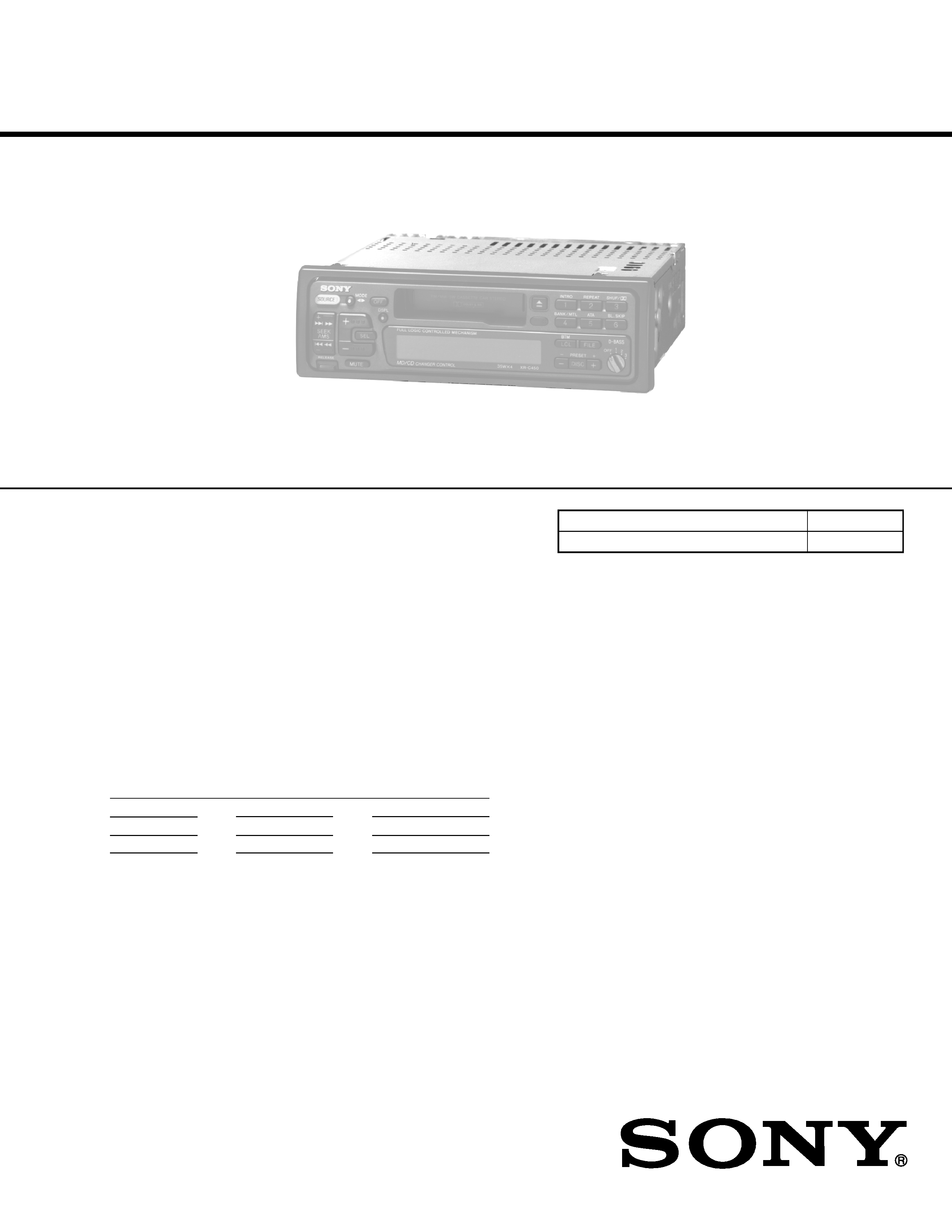
XR-C440/C450: US, Canadian Model
FM/AM CASSETTE CAR STEREO
XR-C450: E Model
FM/MW/SW CASSETTE CAR STEREO
Refer to RM-X2S/X3S SERVICE MANUAL (9-960-039-
)
issued previously for information of remote commander
(RM-X2S) supplied with XR-C440.
Photo: XR-C450
Dolby noise reduction manufactured under license
from Dolby Laboratories Licensing Corporation.
"DOLBY" and the double-D symbol
a are trademarks
of Dolby Laboratories Licensing Corporation.
AUDIO POWER SPECIFICATIONS (US model)
POWER OUTPUT AND TOTAL HARMONIC DISTORTION
12 watts per channel minimum continuous average power into 4 ohms, 4 channels driven from 20 Hz to 20 kHz with no more than 1% total
harmonic distortion.
Ver 1.1 2001.08
9-925-536-12
Sony Corporation
2001H0500-1
e Vehicle Company
C
2001.8
Shinagawa Tec Service Manual Production Group

2
Flexible Circuit Board Repairing
· Keep the temperature of the soldering iron around 270 ° C during
repairing.
· Do not touch the soldering iron on the same conductor of the
circuit board (within 3 times).
· Be careful not to apply force on the conductor when soldering or
unsoldering .
Notes on chip component replacement
· Never reuse a disconnected chip component.
· Notice that the minus side of a tantalum capacitor may be dam-
aged by heat.
TABLE OF CONTENTS
1.
GENERAL
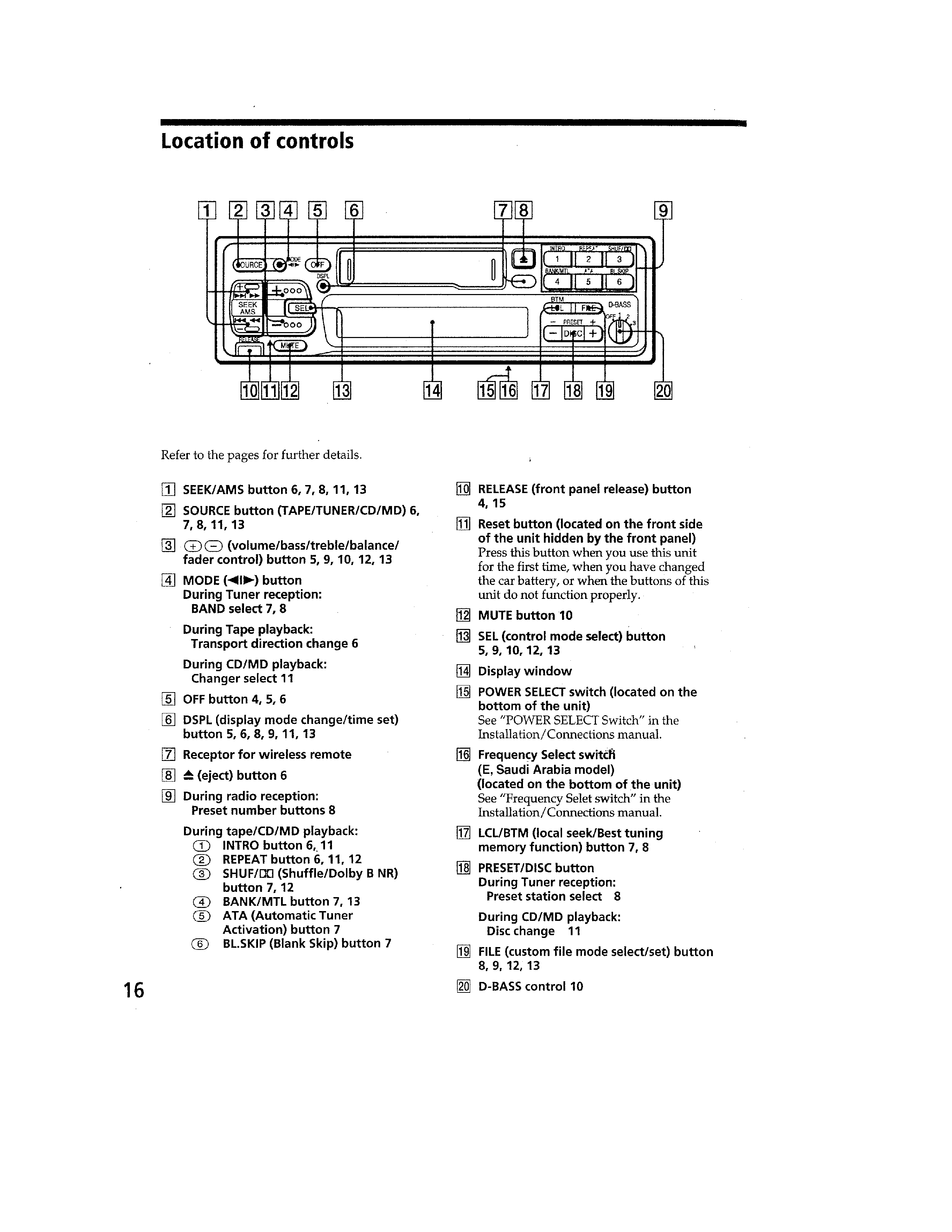
Location of Controls (XR-C440) .......................................
3
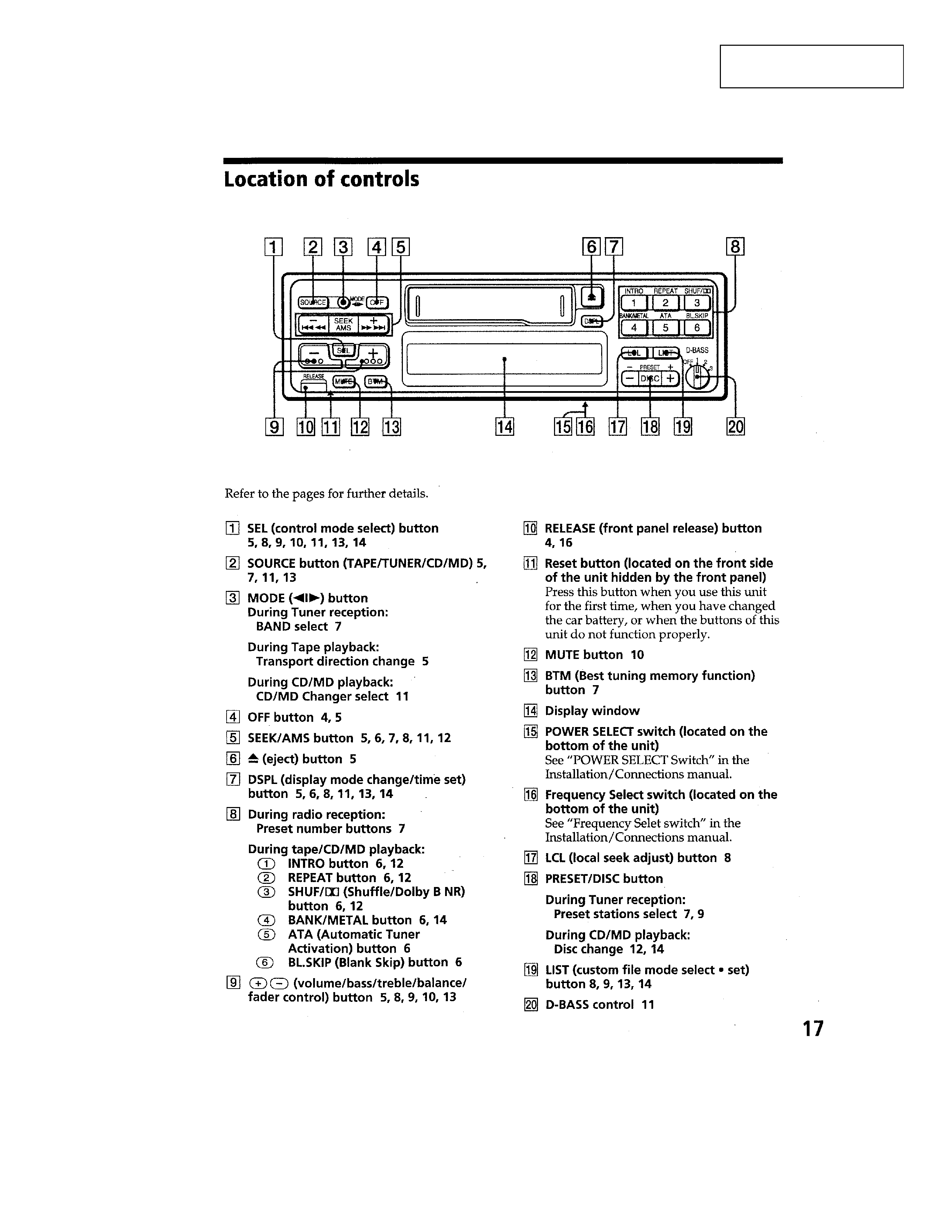
Location of Controls (XR-C450) .......................................
4
Installation (XR-C440/XR-C450: E, saudi Arabia) ...........
6
Installation (XR-C450: US, Canadian) ..............................
7
Installing the rotary remote (XR-C440) ............................
8
Connection (XR-C440) .....................................................
9
Connection (XR-C450) ..................................................... 11
2.
DISASSEMBLY ............................................................ 14
3.
ASSEMBLY OF MECHANISM DECK ............. 16
4.
MECHANICAL ADJUSTMENTS ......................... 19
5.
ELECTRICAL ADJUSTMENTS
Test Mode .......................................................................... 19
Tape Deck Section ............................................................. 20
Tuner Section (XR-C450: E, Saudi Arabia) ...................... 20
6.
DIAGRAMS
6-1.
Printed Wiring Board Main Section .............................. 23
6-2.
Schematic Diagram Main Section ................................ 25
6-3.
Printed Wiring Board Key Section (XR-C440) ............ 29
6-4.
Schematic Diagram Key Section (XR-C440) ............... 31
6-5.
Printed Wiring Board Key Section (XR-C450) ............ 33
6-6.
Schematic Diagram Key Section (XR-C450) ............... 35
6-7.
IC Pin Function Description .............................................. 39
7.
EXPLODED VIEWS .................................................. 41
8.
ELECTRICAL PARTS LIST .................................. 45
AM (MW)
Tuning range
US, Canadian model:
530 1,710 MHz
E, Saudi Arabia model:
9 kHz/10 kHz switchable
531 1,602 kHz
(at 9 kHz step)
530 1,710 kHz
(at 10 kHz step)
SW (C450: E, Saudi Arabia)
Tuning range
SW tuning interval:
SW1: 2,940 7,735 kHz
SW2: 9,500 18,135 kHz
(except for 10,140 11,575 kHz)
Antenna terminal
External antenna connector
Intermediate frequency
10.71 MHz/450 kHz
Sensitivity
30 µV (C440/C450: US, Canadian)
40 µV (C450: E, Saudi Arabia)
Power amplifier section
Outputs
Speaker outputs
(sure seal connectors)
Speaker impedance
4 8 ohms
Maximum power output
35 W
× 4 (at 4 ohms)
General
Outputs
Power antenna control lead
Line out
Rear (1)
Front (1) (C450)
Tone controls
Bass ±8 dB at 100 Hz
Treble ±8 dB at 100 Hz
Power requirements
12 V DC car battery
(negative ground)
Dimensions
Approx. 188
× 58 × 181 mmm
(7 1/2
× 2 3/8 × 7 1/4 in.)
(w / h / d)
Mounting dimensions
Approx. 182
× 53 × 164 mmm
(7 1/4
× 2 1/8 × 6 1/2 in.)
(w / h / d)
Mass
Approx. 1.2 kg (2 lb. 10 oz.)
Supplied accessories
Parts for installation and connections (1 set)
Front panel case (1)
Rotary remote
RM-X2S (C440)
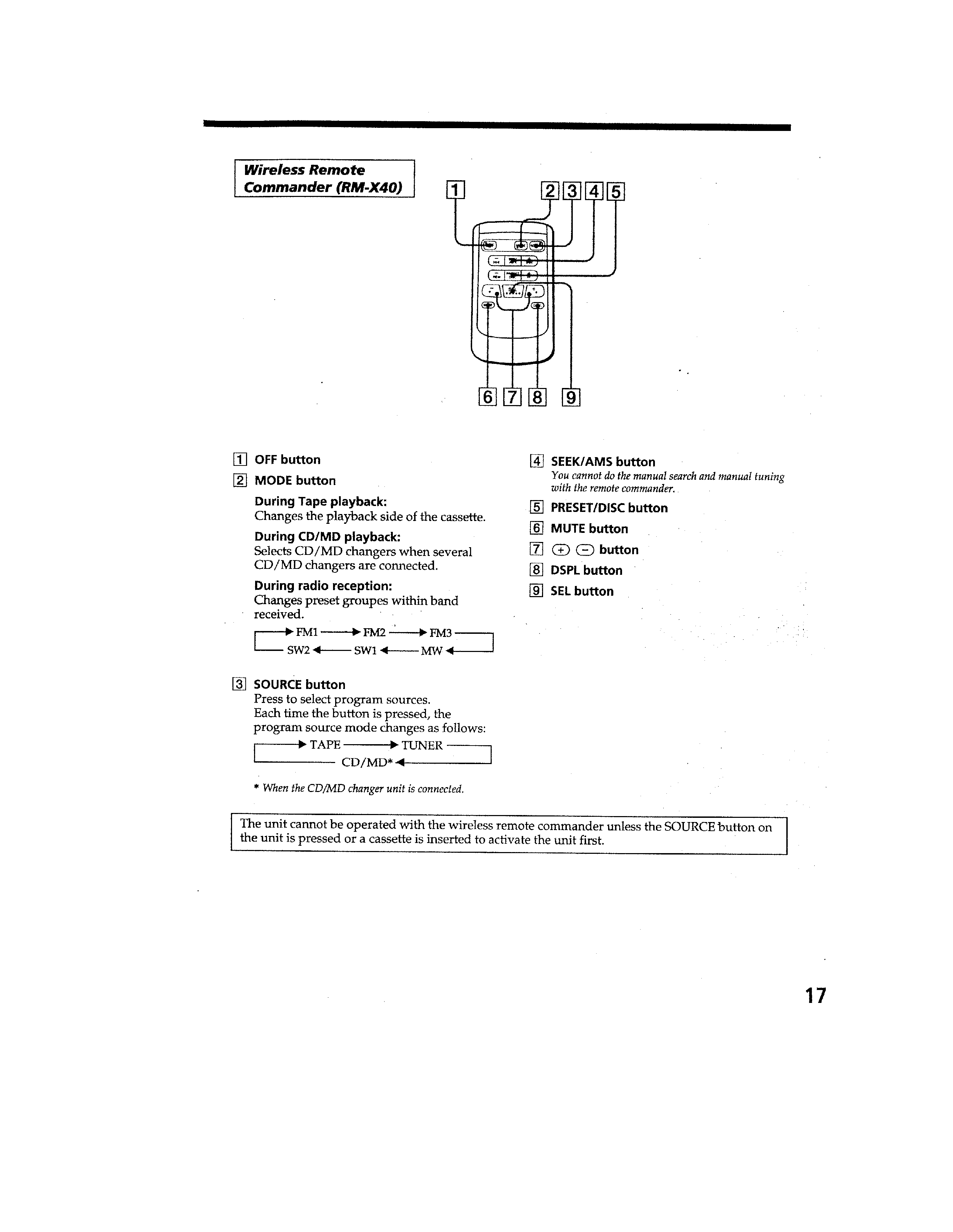
Wireless Remote
Commander RM-X40 (C450: E, Saudi Arabia)
Design and specifications are subject to change without notice.
3
SECTION 1
GENERAL
This section is extracted
from instruction manual.
(XR-C440)
4
(XR-C450)
5
(XR-C450: E, Saudi Arabia)