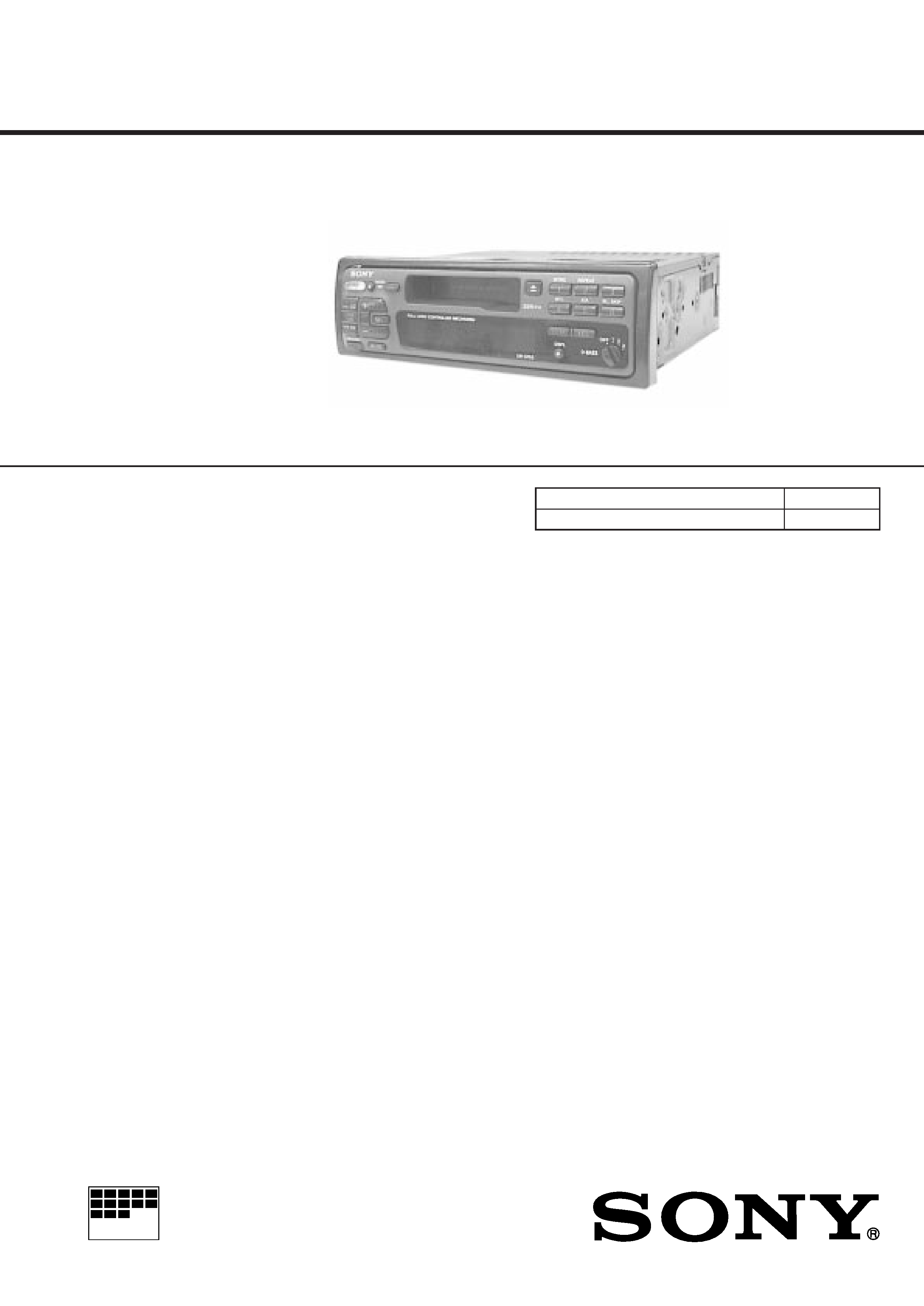
MICROFILM
XR-3753/C353
East European Model
SERVICE MANUAL
FM/MW/LW CASSETTE CAR STEREO
SPECIFICATIONS
Model Name Using Similar Mechanism
NEW
Tape Transport Mechanism Type
MG-25A-136
General
Outputs
Power aerial control lead
Power amplifier control
lead (XR-C353 only)
Telephone mute control
lead (XR-C353 only)
Line out (XR-C353 only)
Tone controls
Bass ± 8 dB at 100 Hz
Treble ± 8 dB at 10 kHz
Power requirements
12 V DC car battery
(negative ground)
Dimensions
Approx. 188
× 58 × 181 mm (w/h/d)
Mounting dimensions
Approx. 182
× 53 × 164 mm (w/h/d)
Mass
Approx. 1.2 kg
Supplied accessories
Parts for installation and connections (1 set)
Front panel case (1)
Rotary commander
RM-X2S
Design and specifications are subject to change without notice.
Photo: XR-3753
Cassette player section
Tape track
4-track 2-channel stereo
Wow and flutter
0.08 % (WRMS)
Frequency response
30 20,000 Hz
Signal-to-noise ratio
58 dB
Tuner section
FM
Turning range
65.0 74.0 MHz
(at 30 kHz step)
87.5 108.0 MHz
(at 50 kHz step)
Aerial terminal
External aerial connector
Intermediate frequency 10.7 MHz
Usable sensitivity
8 dBf
Selectivity
75 dB at 400 kHz
Signal-to-noise ratio
65 dB (stereo),
68 dB (mono)
Harmonic distortion at 1 kHz
0.5 % (stereo),
0.3 % (mono)
Separation
35 dB at 1 kHz
Frequency response
30 15,000 Hz
Capture ratio
2 dB
MW/LW
Tuning range
MW: 531 1,602 kHz
LW: 153 281 kHz
Aerial terminal
External aerial connector
Intermediate frequency 10.71 MHz/450 kHz
Sensitivity
MW: 30 µV
LW: 50 µV
Power amplifier section
Outputs
Speaker outputs
(sure seal connectors)
Speaker impedance
4 8 ohms
Maximum power output 35 W
× 4 (at 4 ohms)
For RM-X2S (Remote Commander),
please refer to RM-X2S/X3S Service
Manual (9-960-039-
) previously issued.

2
TABLE OF CONTENTS
1.
GENERAL
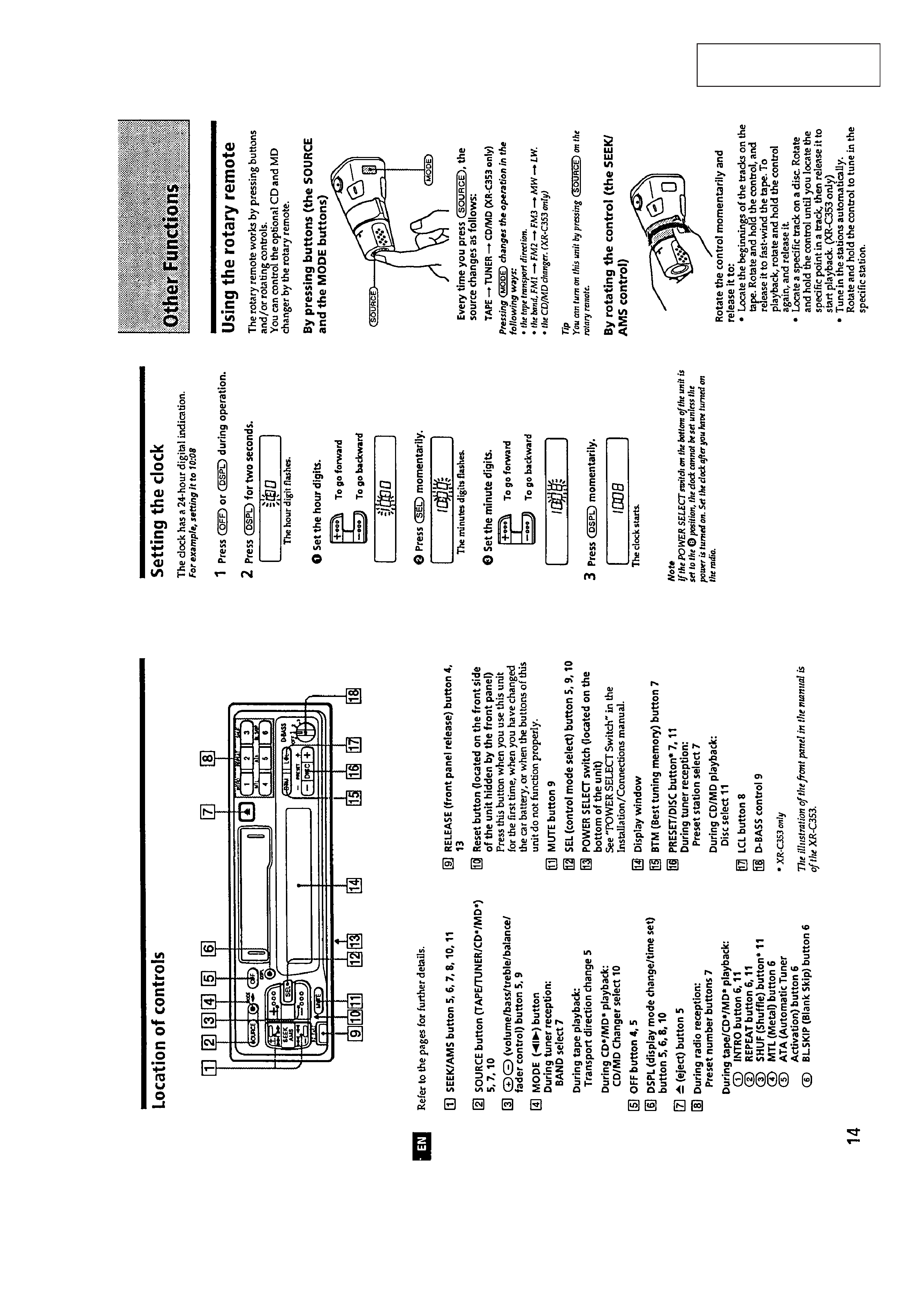
Location of Controls ........................................................ 3
Setting the Clock ............................................................. 3
Using the Rotary Remote ................................................ 3
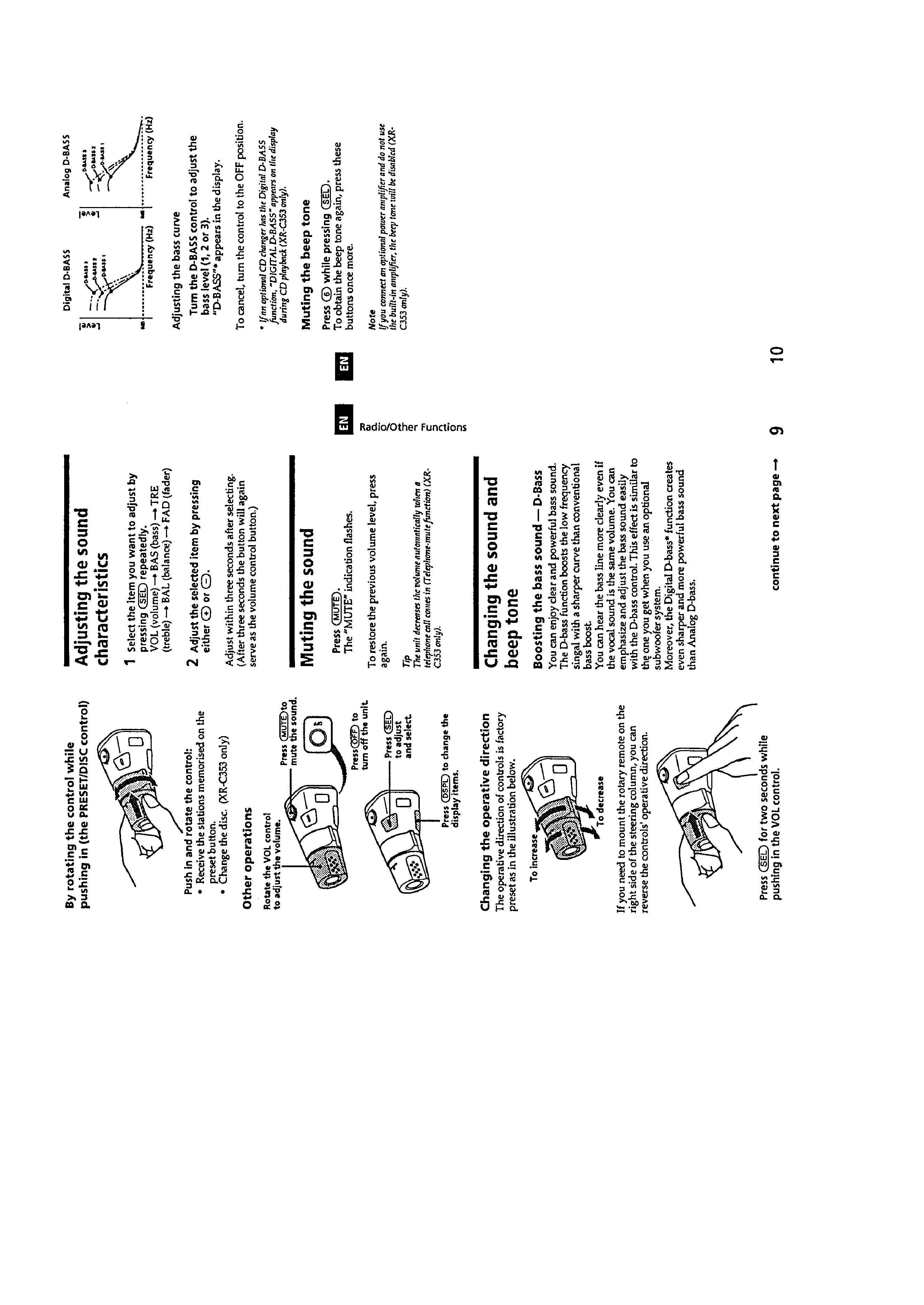
Adjusting the Sound Characteristics ............................... 4
Muting the Sound ............................................................ 4
Changing the Sound and Beep Tone ................................ 4
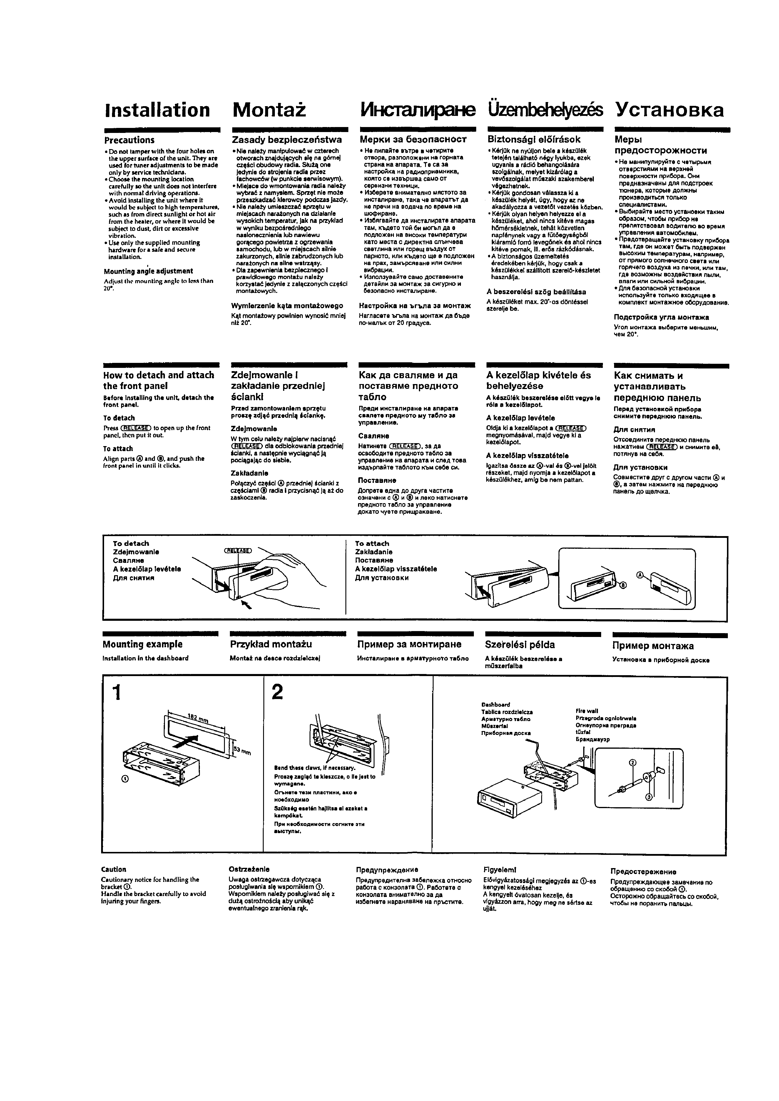
Installation ....................................................................... 5
Connections ..................................................................... 6
2.
DISASSEMBLY .......................................................... 9
3.
ASSEMBLY OF MECHANISM DECK ............. 11
4.
MECHANICAL ADJUSTMENTS ....................... 14
5.
ELECTRICAL ADJUSTMENTS
Test Mode ........................................................................ 14
Tape Deck Section ........................................................... 14
Tuner Section ................................................................... 15
6.
DIAGRAMS
6-1. Printed Wiring Board Main Section ........................... 21
6-2. Schematic Diagram Main Section .............................. 23
6-3. Printed Wiring Board Panel Section ........................... 27
6-4. Schematic Diagram Panel Section .............................. 29
6-5. IC Pin Function Description ............................................ 31
7.
EXPLODED VIEWS ................................................ 33
8.
ELECTRICAL PARTS LIST ................................ 36
SERVICING NOTES
Flexible Circuit Board Repairing
· Keep the temperature of the soldering iron around 270 ° C during
repairing.
· Do not touch the soldering iron on the same conductor of the
circuit board (within 3 times).
· Be careful not to apply force on the conductor when soldering or
unsoldering .
Notes on chip component replacement
· Never reuse a disconnected chip component.
· Notice that the minus side of a tantalum capacitor may be dam-
aged by heat.
3
SECTION 1
GENERAL
This section is extracted
from instruction manual.
4
5