AEP Model
UK Model
Model Name Using Similar Mechanism
XR-C6100R
Tape Transport Mechanism Type
MG-25F-136
SPECIFICATIONS
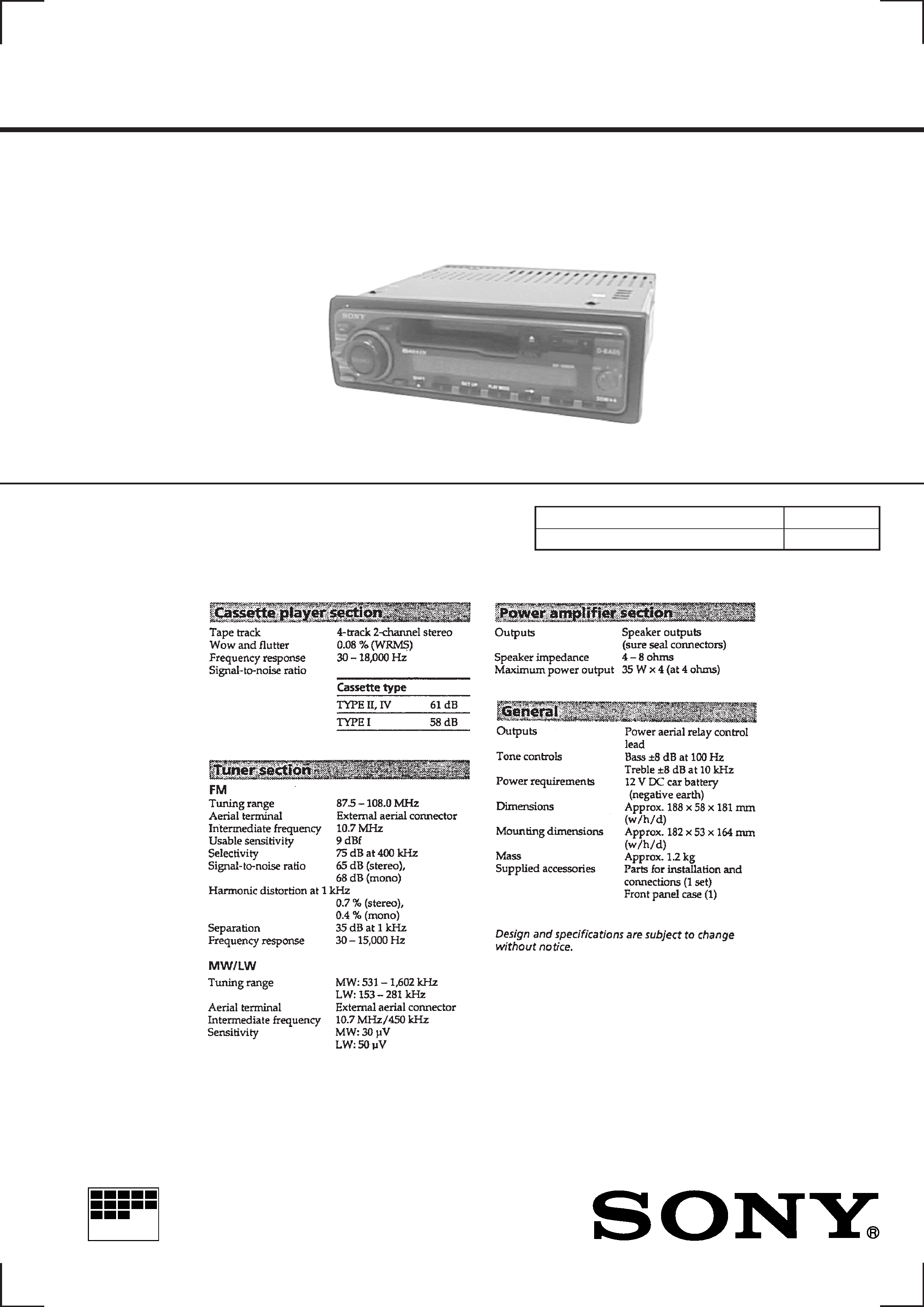
XR-4880
Photo: XR-4880
FM/MW/LW CASSETTE CAR STEREO
MICROFILM
SERVICE MANUAL

2
TABLE OF CONTENTS
1.
GENERAL
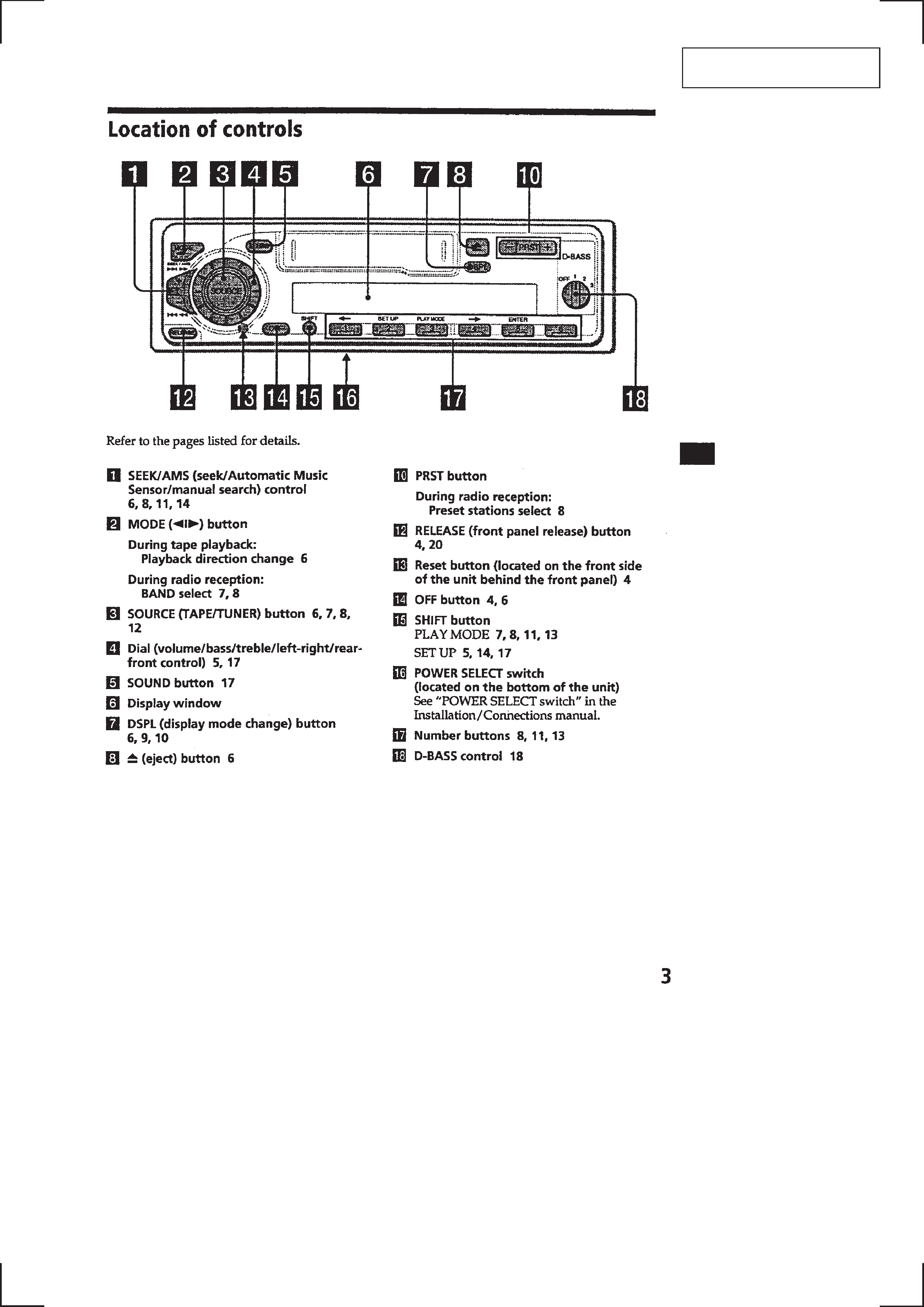
Location of Controls ....................................................... 3
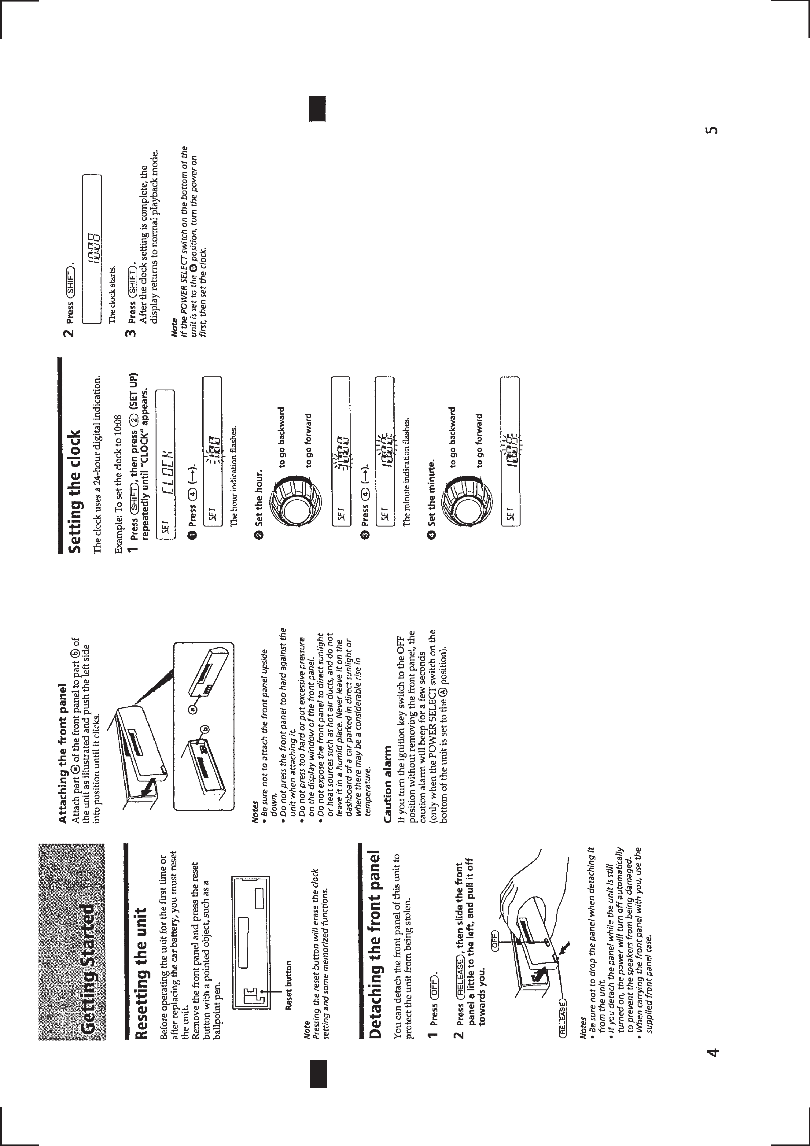
Resetting the Unit ........................................................... 4
Detaching the Front Panel ............................................... 4
Setting the Clock ............................................................. 4
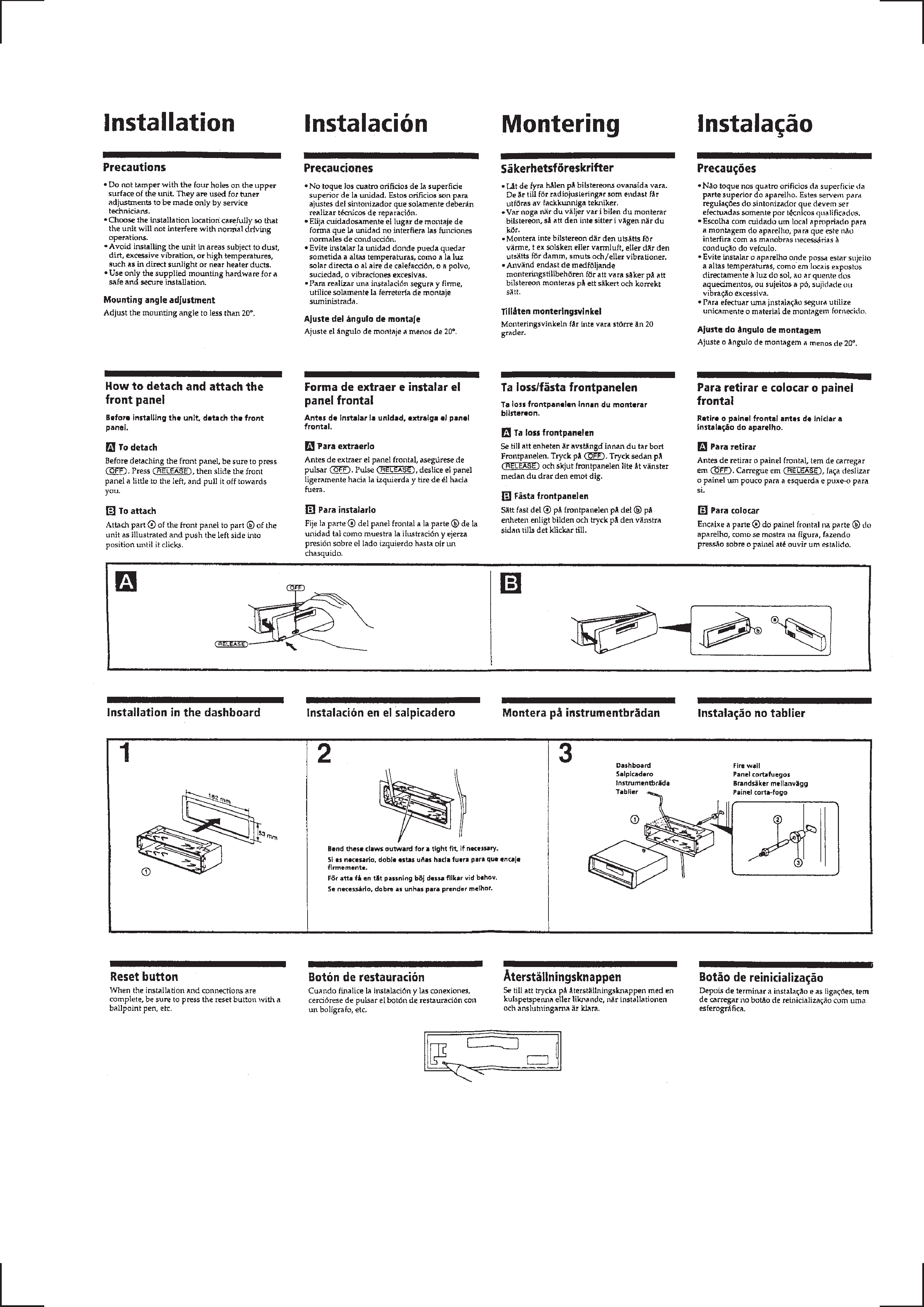
Installation ....................................................................... 5
Connections ..................................................................... 6
2.
DISASSEMBLY ......................................................... 8
3.
ASSEMBLY OF MECHANISM DECK ............ 10
4.
MECHANICAL ADJUSTMENTS ....................... 13
5.
ELECTRICAL ADJUSTMENTS
Test Mode ........................................................................ 13
Tape Deck Section .......................................................... 13
Tuner Section .................................................................. 14
6.
DIAGRAMS ................................................................. 17
6-1. Printed Wiring Board MAIN Section ........................ 19
6-2. Schematic Diagram MAIN (1/2) Section .................. 21
6-3. Schematic Diagram MAIN (2/2) Section .................. 23
6-4. Printed Wiring Board PANEL Section ...................... 25
6-5. Schematic Diagram PANEL Section ......................... 27
6-6. IC Pin Function Description ........................................... 29
7.
EXPLODED VIEWS ................................................ 31
8.
ELECTRICAL PARTS LIST ............................... 34
Flexible Circuit Board Repairing
· Keep the temperature of the soldering iron around 270 °C dur-
ing repairing.
· Do not touch the soldering iron on the same conductor of the
circuit board (within 3 times).
· Be careful not to apply force on the conductor when soldering
or unsoldering.
Notes on chip component replacement
· Never reuse a disconnected chip component.
· Notice that the minus side of a tantalum capacitor may be dam-
aged by heat.
3
SECTION 1
GENERAL
This section is extracted from
instruction manual.
4
5