MICROFILM
XR-3758/3759
FM/MW/LW CASSETTE CAR STEREO
SERVICE MANUAL
UK Model
Model Name Using Similar Mechanism
XR-3750/C350
Tape Transport Mechanism Type
MG-52A-135
· XR-3758/3759 are almost same as XR-3750 UK model.
Printed wiring boards, schematic diagram, exploded views
and electrical parts list are described in this service manual.
Please refer to XR-3750/C350 service manual previously
issued for the other informations.
TABLE OF CONTENTS
1.
EXPLODED VIEWS ................................................ 2
2.
DIAGRAMS
2-1. Printed Wiring Boards MAIN Section ........................ 6
2-2. Schematic Diagram MAIN Section ............................ 9
2-3. Printed Wiring Board KEY Section ........................... 14
2-4. Schematic Diagram KEY Section .............................. 16
3.
ELECTRICAL PARTS LIST ................................ 19
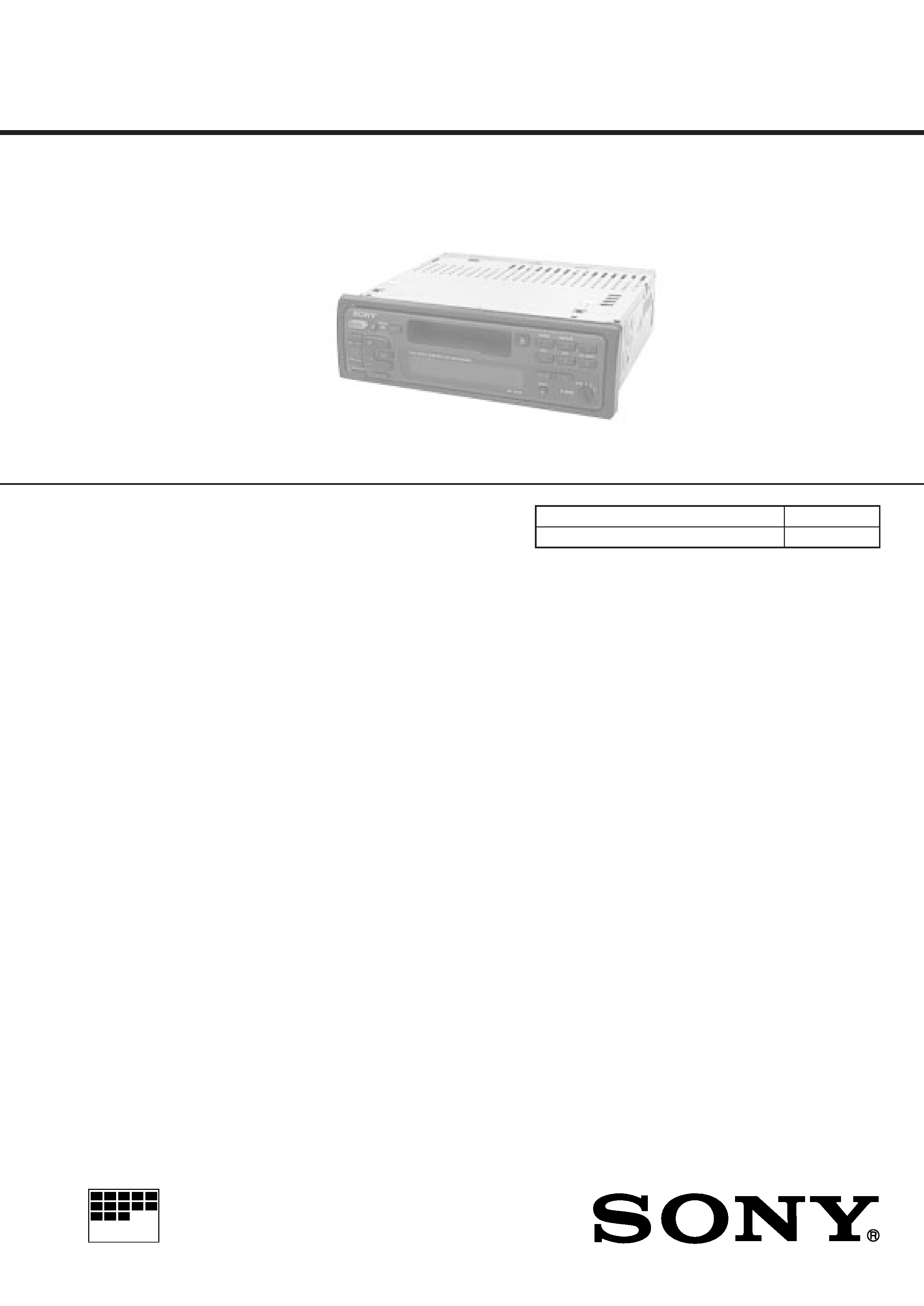
Photo: XR-3759
SERVICING NOTES
Flexible Circuit Board Repairing
· Keep the temperature of the soldering iron around 270 ° C dur-
ing repairing.
· Do not touch the soldering iron on the same conductor of the
circuit board (within 3 times).
· Be careful not to apply force on the conductor when soldering
or unsoldering
Notes on chip component replacement
· Never reuse a disconnected chip component.
· Notice that the minus side of a tantalum capacitor may be dam-
aged by heat.
2
NOTE:
· -XX and -X mean standardized parts, so they
may have some difference from the original
one.
· Color Indication of Appearance Parts
Example:
KNOB, BALANCE (WHITE) . . . (RED)
Parts Color
Cabinet's Color
· Items marked "*" are not stocked since they
are seldom required for routine service. Some
delay should be anticipated when ordering
these items.
· The mechanical parts with no reference num-
ber in the exploded views are not supplied.
· Hardware (# mark) list and accessories and
packing materials are given in the last of the
electrical parts list.
SECTION 1
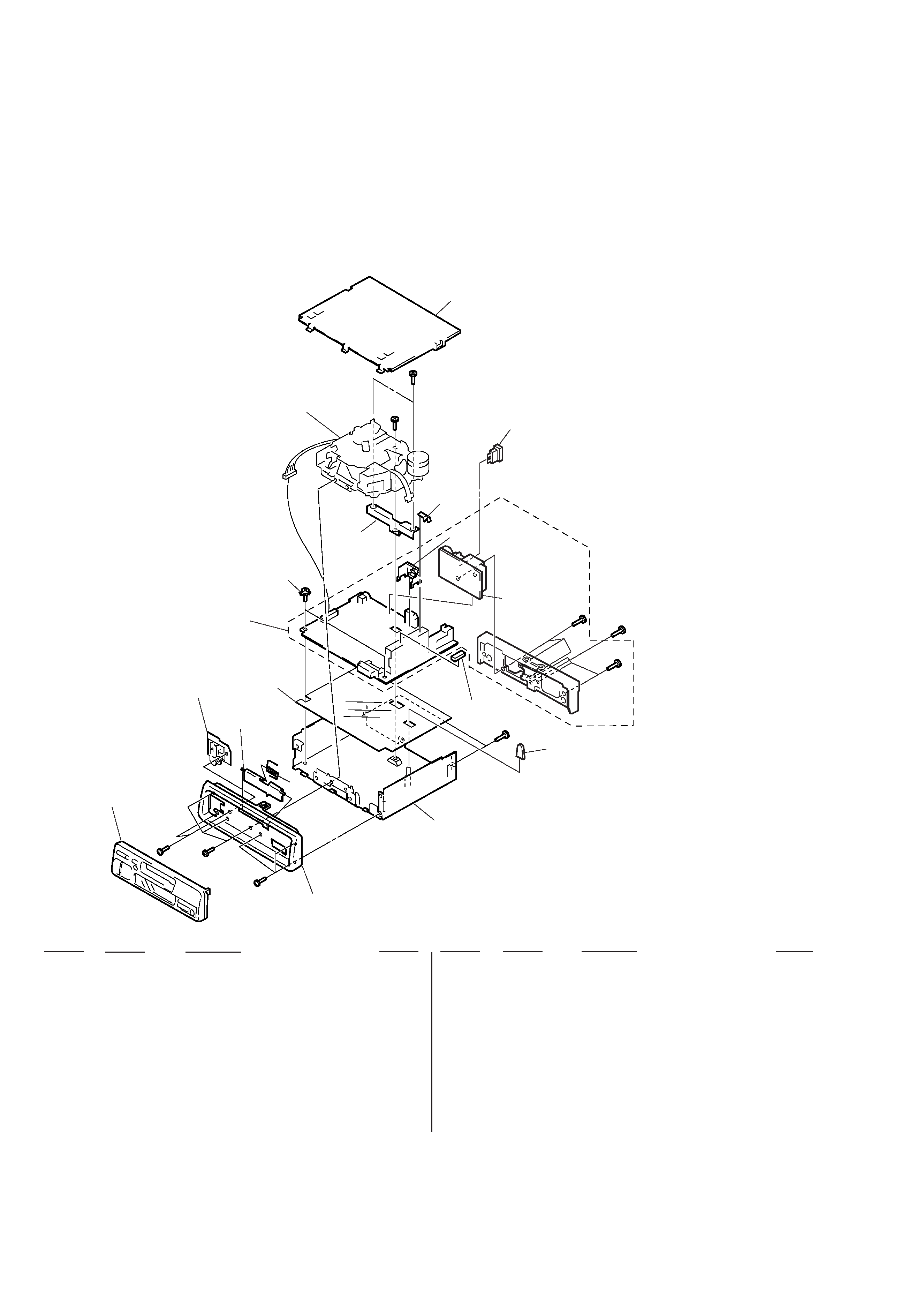
EXPLODED VIEWS
Ref. No.
Part No.
Description
Remark
Ref. No.
Part No.
Description
Remark
1
3-009-294-01 PANEL, SUB
2
3-935-003-01 SPRING, TORSION
3
3-932-205-21 DOOR, CASSETTE (XR-3758)
3
3-932-205-71 DOOR, CASSETTE (XR-3759)
4
X-3367-636-1 LOCK ASSY
* 5
3-010-376-01 INSULATOR
* 6
A-3309-950-A MAIN BOARD, COMPLETE (XR-3759)
* 6
A-3309-953-A MAIN BOARD, COMPLETE (XR-3758)
7
3-915-923-01 SCREW, GROUND POINT
* 8
X-3373-504-1 COVER ASSY
* 10
3-012-264-01 BRACKET (52)
* 11
3-010-471-01 HEAT SINK
12
9-911-840-XX CUSHION (U)
* 13
3-009-813-11 CHASSIS (XR-3758)
* 13
3-009-813-31 CHASSIS (XR-3759)
* 15
A-3309-913-A CONNECTOR BOARD, COMPLETE (XR-3758)
* 15
A-3313-078-A CONNECTOR BOARD, COMPLETE (XR-3759)
* 18
3-012-860-01 CAP (52), RUBBER
* 19
3-009-816-01 BRACKET (IC) (ISO)
F801
1-532-877-11 FUSE (BLADE TYPE) (AUTO FUSE) (10A)
(1) CHASSIS SECTION
8
F801
10
#3
MG-52A-135
7
6
5
4
3
Front panel ass'y
#2
#3
#3
1
2
18
#3
13
15
#3
12
#3
19
not
supplied
#1
#1
3
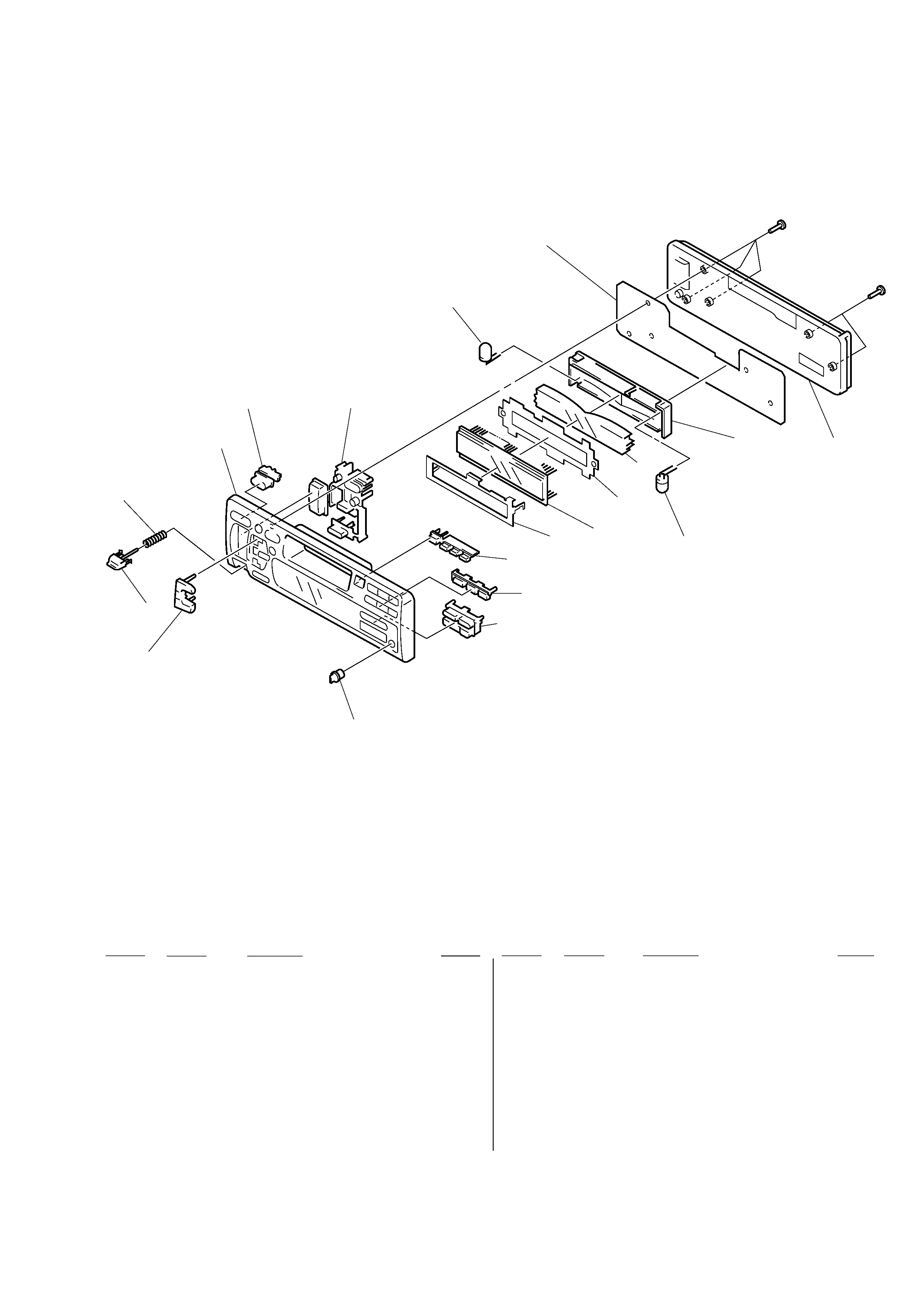
(2) FRONT PANEL SECTION
53
54
52
59
60
62
LCD901
not supplied
(KEY board)
#5
#5
PL901
65
66
61
51
Ref. No.
Part No.
Description
Remark
Ref. No.
Part No.
Description
Remark
51
3-009-301-01 BUTTON (BASS)
52
3-010-472-01 BUTTON (L2) (+. )
53
3-009-304-01 BUTTON (RELEASE)
54
3-935-119-01 SPRING (RELEASE)
56
X-3373-702-1 PANEL SUB ASSY (XR-3759)
56
X-3373-703-1 PANEL SUB ASSY (XR-3758)
57
3-009-300-01 BUTTON (SOURCE)
58
3-009-297-11 BUTTON (L) (+
+ ). SEEK AMS.
= 0 . r. OFF. SEL. MUTE)
59
3-010-473-01 BUTTON (13) (
6. 1. 2. 3)
60
3-010-474-11 BUTTON (46) (4. 5. 6)
61
3-009-315-01 BUTTON (R) (3) (BTM. LCL. DSPL)
* 62
3-010-282-01 PLATE (LCD), GROUND
* 63
3-012-669-01 SHEET (REFLECTOR)
* 64
3-009-302-01 PLATE (LCD), LIGHT GUIDE
* 65
3-009-303-02 HOLDER (LCD)
66
3-010-519-01 PANEL, FRONT BACK
LCD901 1-801-678-11 DISPLAY PANEL, LIQUID CRYSTAL
PL901
1-517-633-21 LAMP, PILOT (LCD BACK LIGHT)
PL902
1-517-633-21 LAMP, PILOT (LCD BACK LIGHT)
58
57
56
64
63
PL902
4
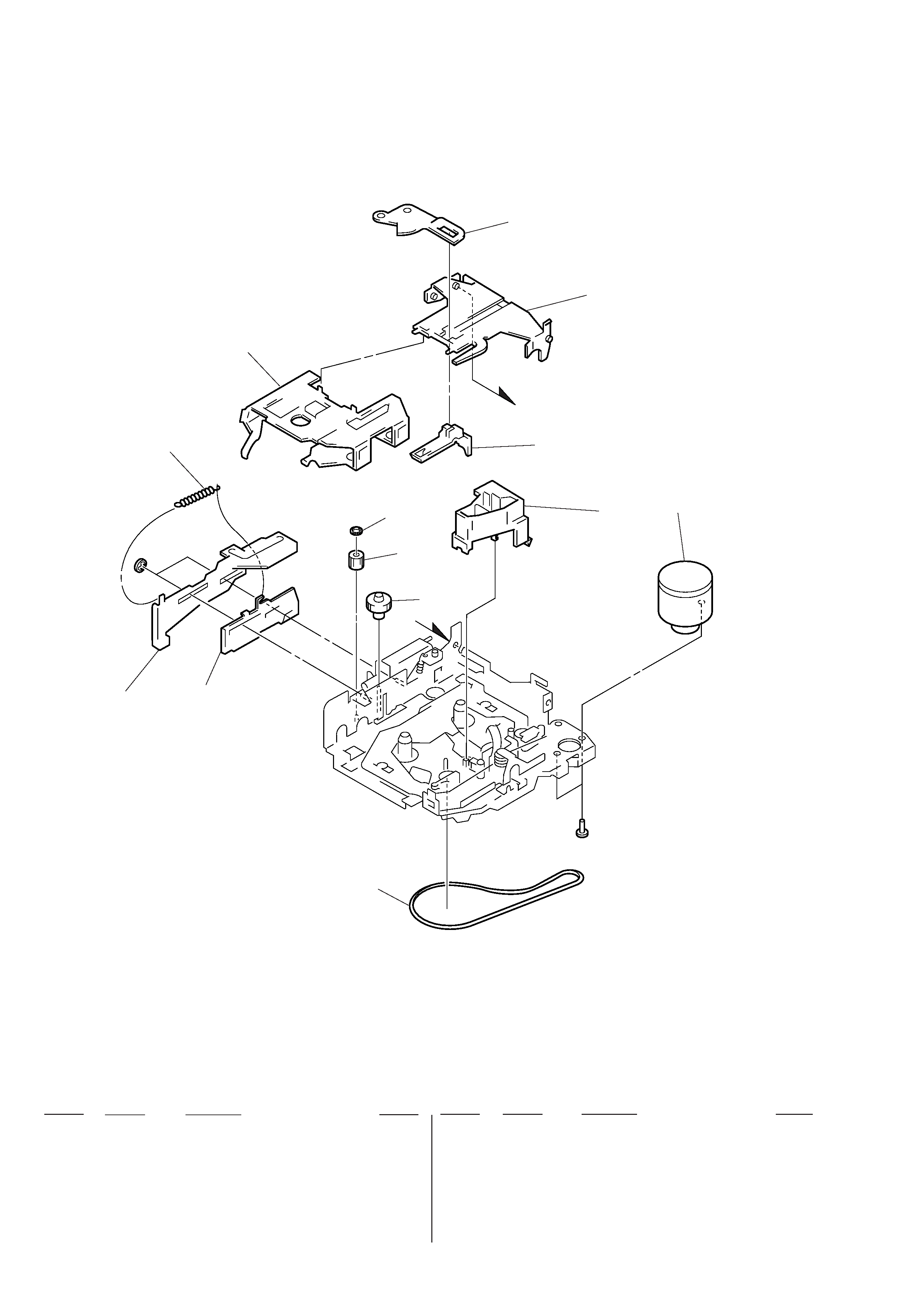
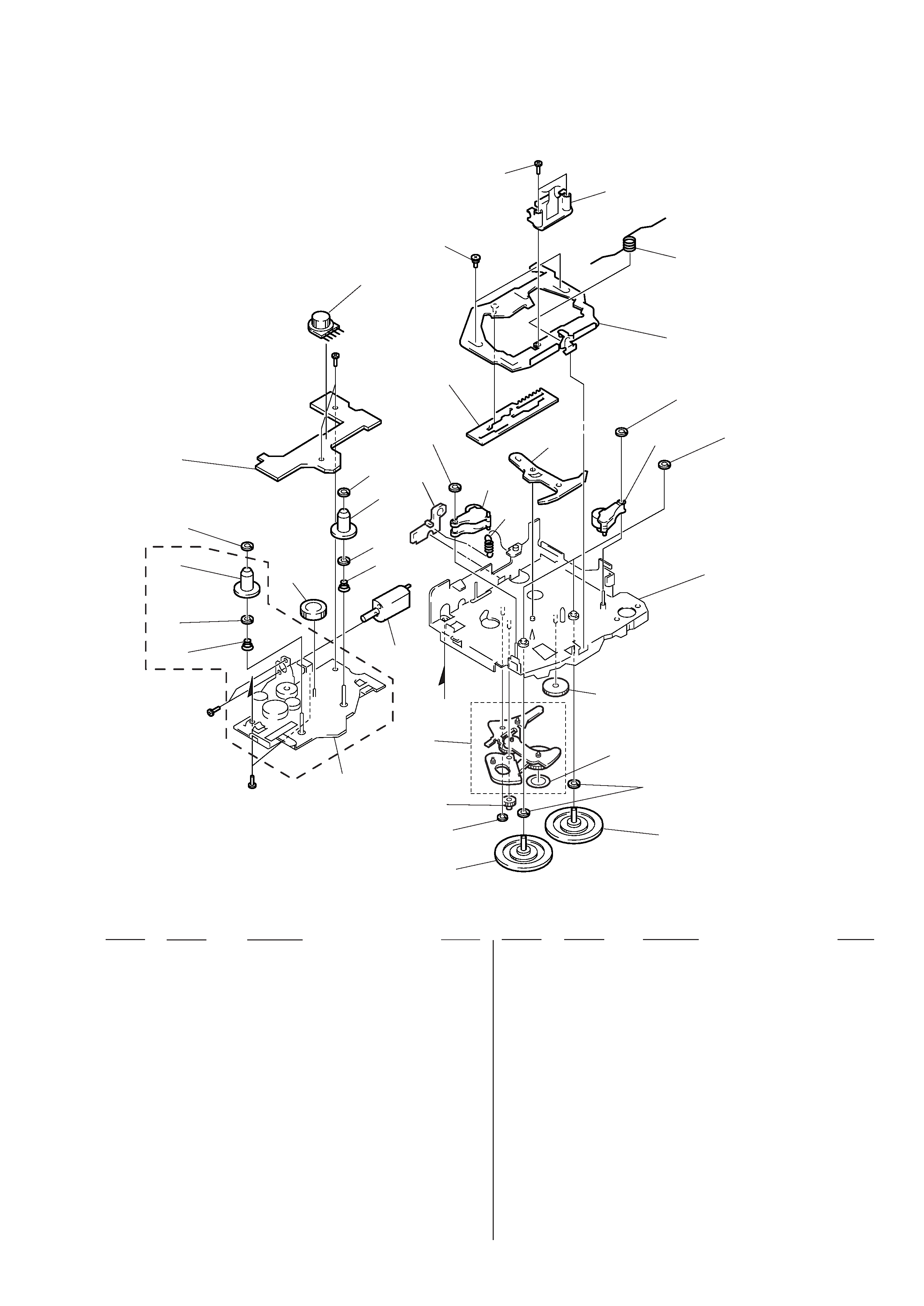
(3) MECHANISM DECK SECTION-1
(MG-52A-135)
106
107
108
109
M901
110
111
112
102
103
#7
104
105
A
A
#6
101
Ref. No.
Part No.
Description
Remark
Ref. No.
Part No.
Description
Remark
101
3-928-675-01 BELT (52)
* 102
3-928-673-01 LEVER (LDG-A)
103
3-928-674-01 LEVER (LDG-B)
104
3-933-341-01 SPRING (LEVER LDG), TENSION
105
3-928-671-01 HOUSING
* 106
3-933-347-01 ARM (SUCTION)
107
3-933-340-01 HANGER
108
3-933-346-01 CATCHER
109
3-933-344-01 GUIDE (C)
110
3-341-753-11 WASHER, POLYETHYLENE
111
3-933-335-01 GEAR (LDG-FT)
112
3-928-667-01 GEAR (LDG-A)
5
(4) MECHANISM DECK SECTION-2
(MG-52A-135)
HP901
165
166
159
167
168
169
170
171
172
173
174
176
151
152
153
156
157
158
154
155
153
156
S901
#6
163
164
159
160
161
M902
B
B
#6
175
#8
162
Ref. No.
Part No.
Description
Remark
Ref. No.
Part No.
Description
Remark
M901
A-3291-665-A MOTOR ASSY, MAIN (CAPSTAN/REEL)
151
X-3371-710-1 CHASSIS (S) ASSY
152
3-933-337-01 SPRING (B-T-R), CONE COIL
153
3-701-437-01 POLY-SLIDER (A)
154
3-933-333-01 GEAR (LDG-E)
155
3-933-339-01 SPRING (B-T-F), CONE COIL
156
3-933-345-01 GEAR, REEL
157
3-954-807-01 WASHER
158
1-660-169-21 REEL BOARD
159
3-341-752-11 WASHER, POLYETHYLENE
160
3-933-336-01 SPRING (ARM HANGER), TENSION
161
3-928-669-01 LEVER (PINCH SELECTION)
162
3-928-668-01 LEVER (MODE)
163
3-933-338-01 SCREW (HP), STEP
164
3-927-100-01 SCREW (+PS 2X10), SPECIAL
165
3-928-670-01 SPRING (PINCH PRESS)
* 166
X-3371-712-1 PLATE SUB ASSY, HEAD
167
3-364-151-01 WASHER
* 168
X-3371-701-1 CHASSIS (M) SUB ASSY (A)
169
X-3371-707-1 CLUTCH (PLAY) ASSY
170
3-701-437-21 WASHER
171
3-930-932-01 FLYWHEEL (F) (SEF)
172
A-3291-667-A CLUTCH (FR) ASSY
173
3-321-813-01 WASHER, COTTER POLYETHYLENE
174
3-933-343-01 GEAR (REVERSE)
175
3-933-383-01 SEAL (32), REFLECTION
176
X-3371-703-1 LEVER (GEAR) ASSY
177
X-3371-713-2 LEVER (PINCH) ASSY
178
X-3371-706-2 ARM (HANGER) ASSY
HP901
1-500-157-21 HEAD, MAGNETIC (PLAYBACK)
M902
A-3291-664-A MOTOR ASSY, SUB
(LOADING/TAPE OPERATION)
S901
1-692-885-11 SWITCH, ROTARY SLIDE (TAPE OPERATION)
177
177
178
157