MICROFILM
XR-3750/C350
AEP Model
UK Model
SERVICE MANUAL
FM/MW/LW CASSETTE CAR STEREO
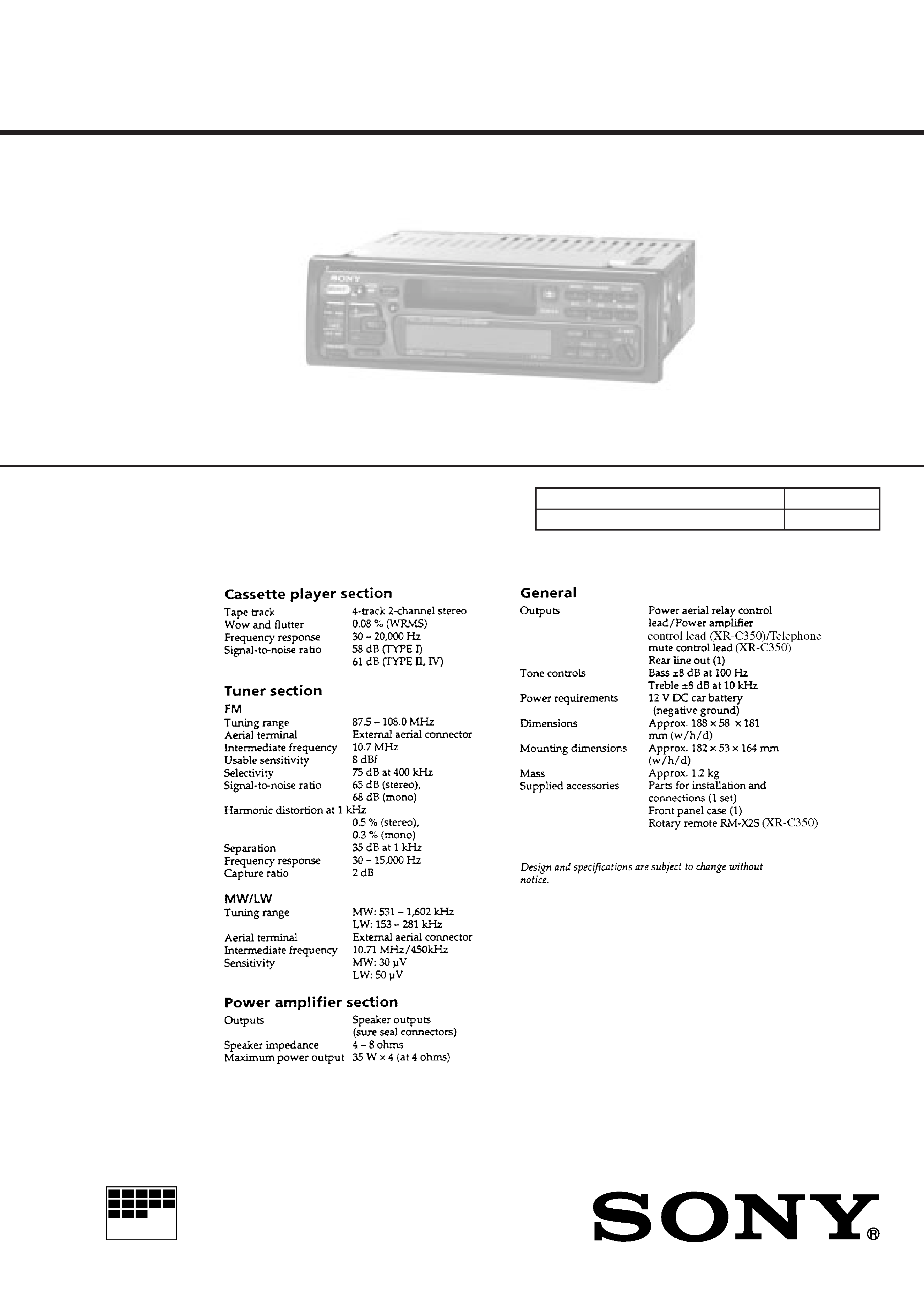
SPECIFICATIONS
Model Name Using Similar Mechanism
NEW
Tape Transport Mechanism Type
MG-52A-135
Refer to RM-X2S/X3S SERVICE MANUAL (9-960-039-
)
issued previously for information of remote commander
(RM-X2S) supplied with XR-C350.
Photo: XR-C350

2
TABLE OF CONTENTS
1.
GENERAL
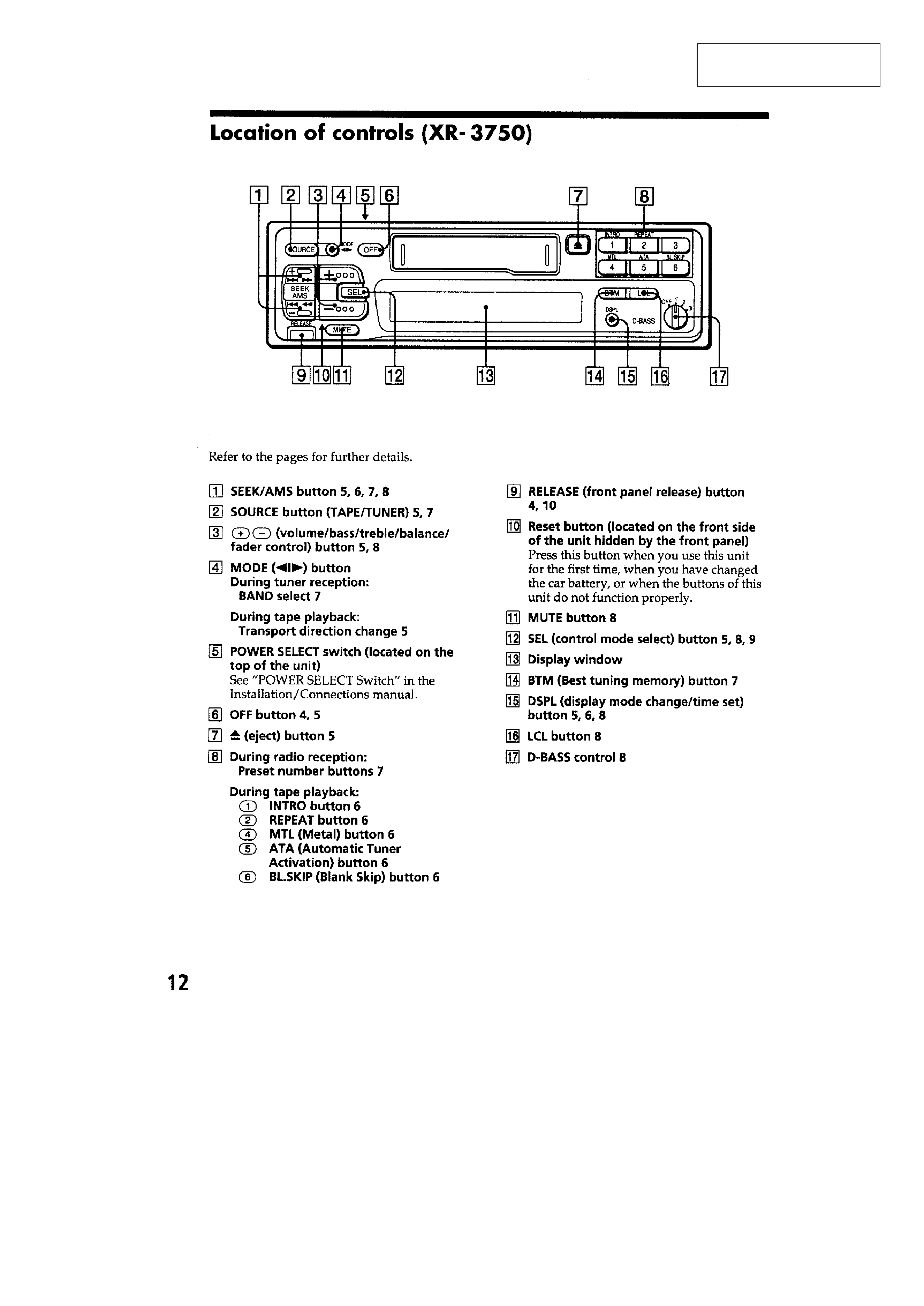
Location of Controls (XR-3750) ..................................... 3
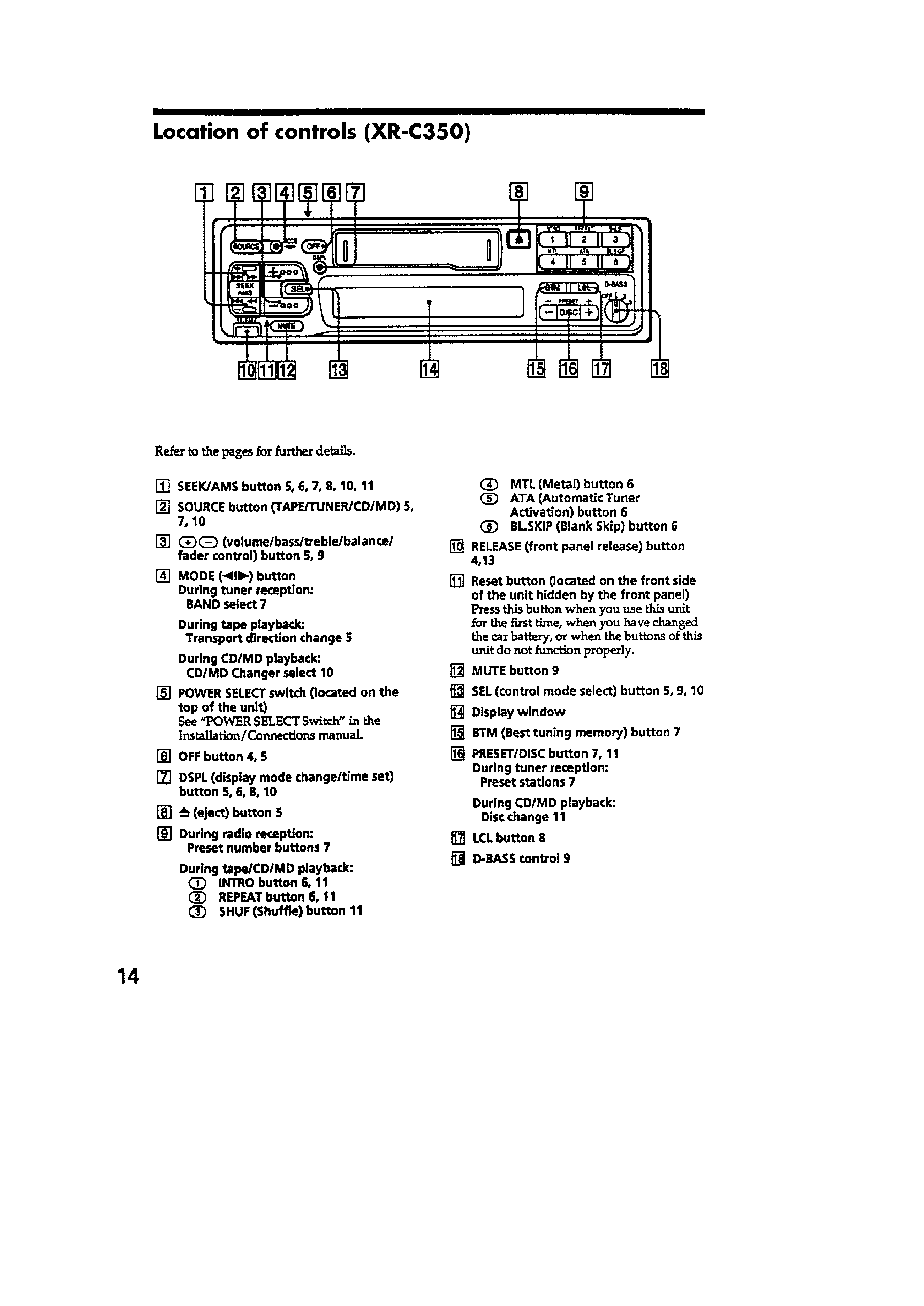
Location of Controls (XR-C350) ..................................... 4
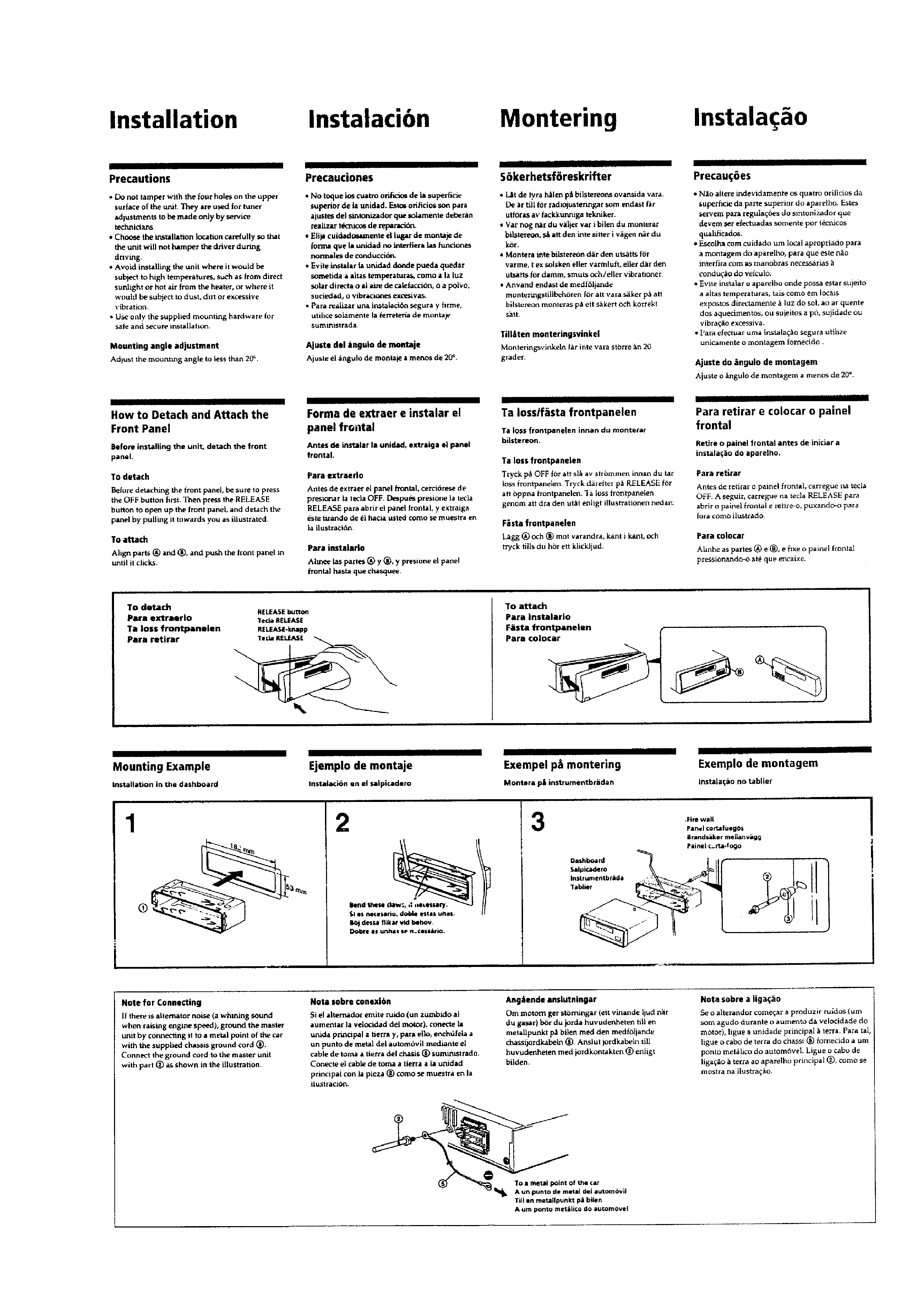
Installation ....................................................................... 5
Connections ..................................................................... 6
2.
DISASSEMBLY .......................................................... 10
3.
ASSEMBLY OF MECHANISM DECK ........... 12
4.
MECHANICAL ADJUSTMENTS ....................... 18
5.
ELECTRICAL ADJUSTMENTS
Test Mode ........................................................................ 18
Tape Deck Section ........................................................... 19
Tuner Section ................................................................... 19
6.
DIAGRAMS
6-1. IC Pin Function Description ............................................ 22
6-2. Printed Wiring Boards Main Section ........................... 24
6-3. Schematic Diagram Main Section .............................. 27
6-4. Printed Wiring Board Key Section ............................. 32
6-5. Schematic Diagram Key Section ................................ 34
7.
EXPLODED VIEWS ................................................ 39
8.
ELECTRICAL PARTS LIST ................................ 43
SERVICING NOTES
Flexible Circuit Board Repairing
· Keep the temperature of the soldering iron around 270 ° C dur-
ing repairing.
· Do not touch the soldering iron on the same conductor of the
circuit board (within 3 times).
· Be careful not to apply force on the conductor when soldering
or unsoldering
Notes on chip component replacement
· Never reuse a disconnected chip component.
· Notice that the minus side of a tantalum capacitor may be dam-
aged by heat.
3
SECTION 1
GENERAL
This section is extracted
from instruction manual.
4
5