MICROFILM
SERVICE MANUAL
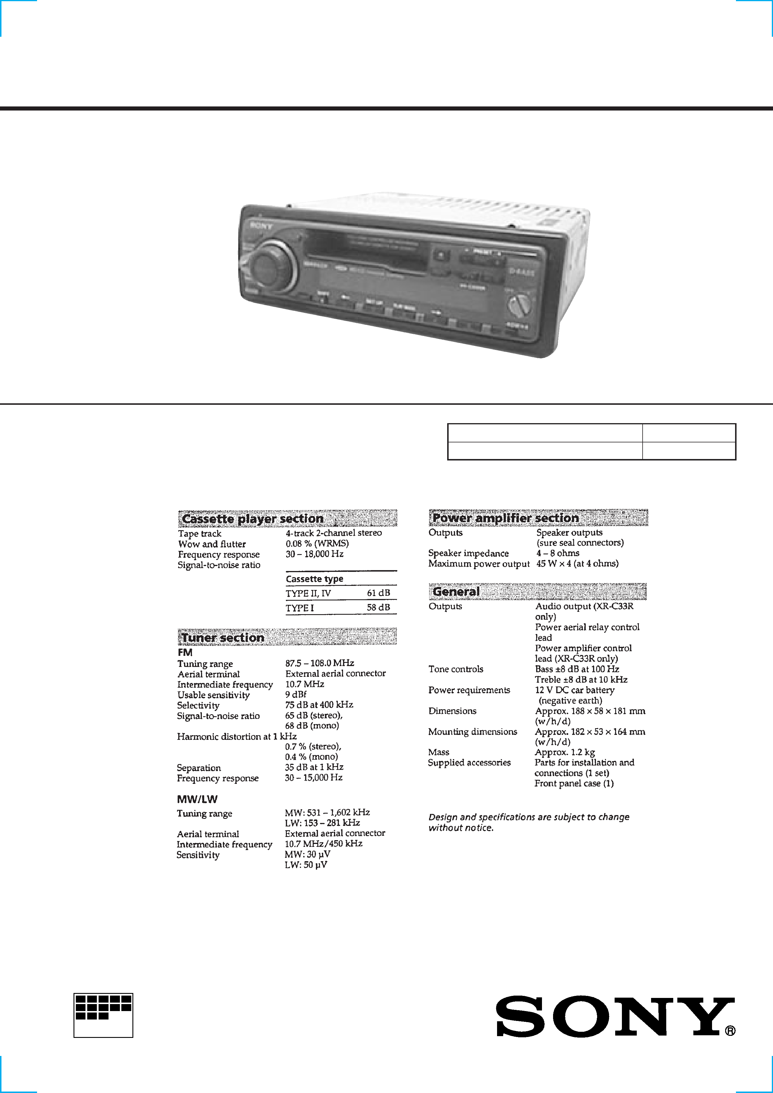
FM/MW/LW CASSETTE CAR STEREO
AEP Model
UK Model
SPECIFICATIONS
XR-3100R/C33R
Photo: XR-C33R
Model Name Using Similar Mechanism
XR-C5100R
Tape Transport Mechanism Type
MG-25G-136

2
TABLE OF CONTENTS
1.
GENERAL
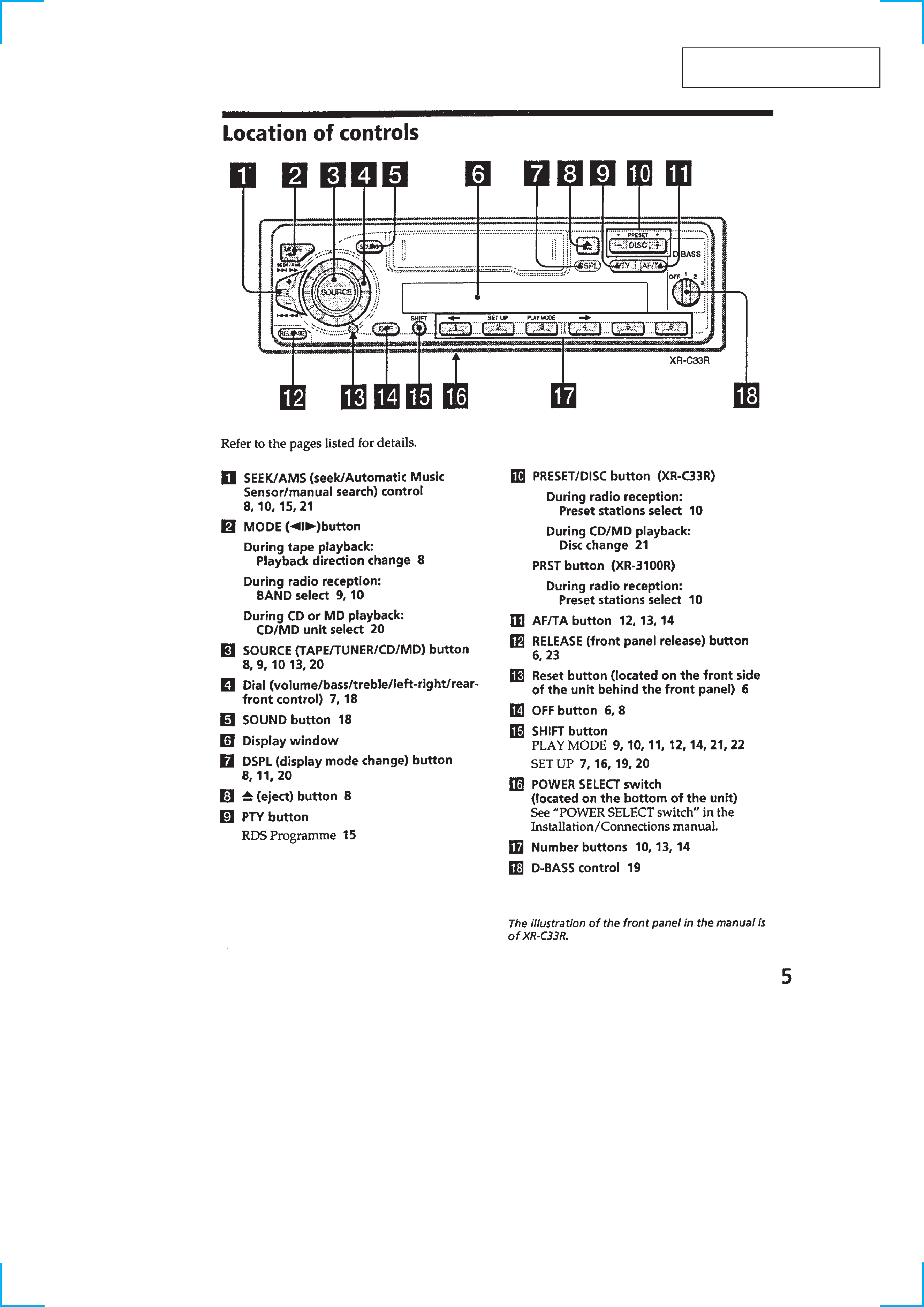
Location of controls ........................................................
3
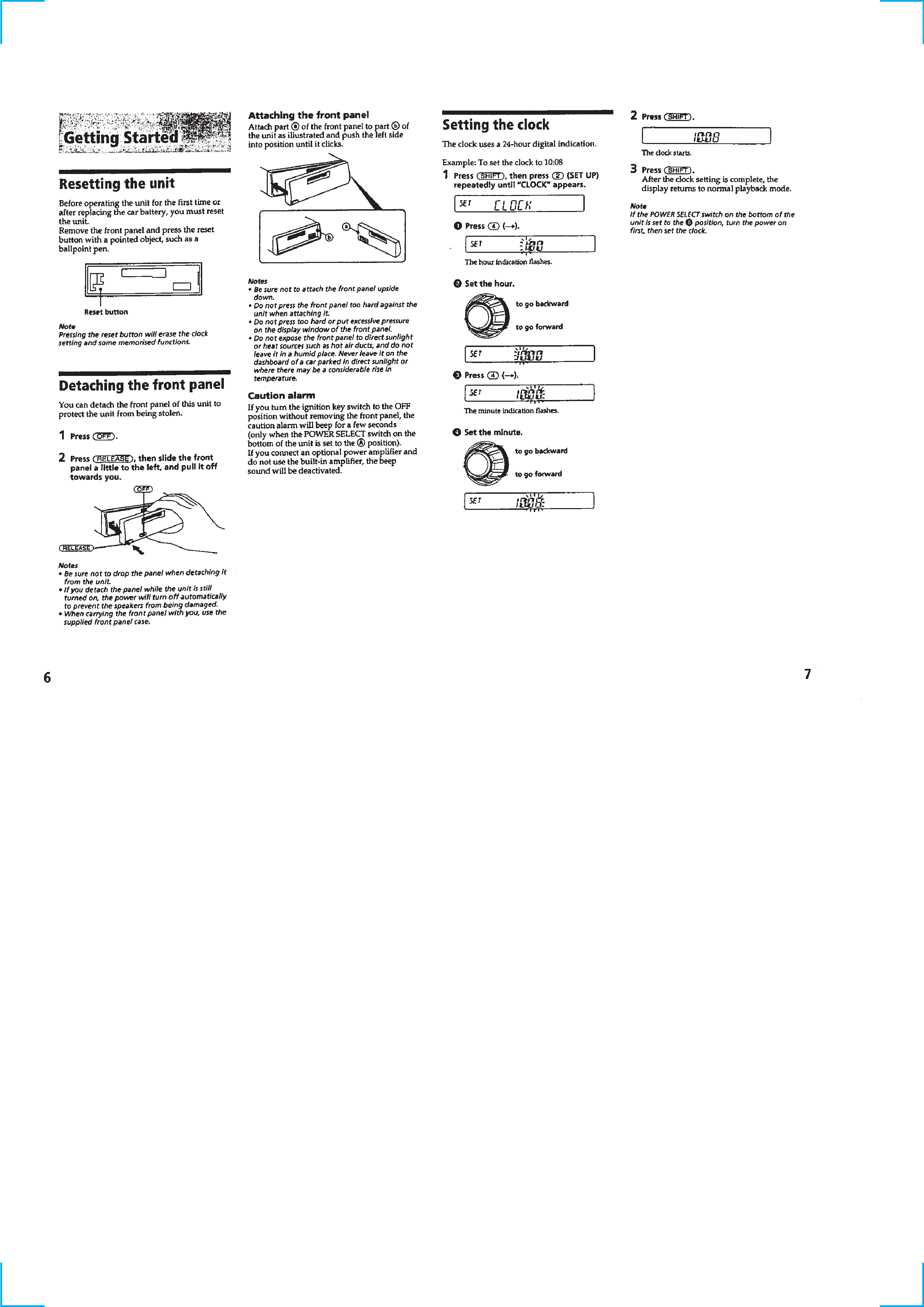
Resetteing the unit ...........................................................
4
Detaching the front panel ................................................
4
Setting the clock ..............................................................
4
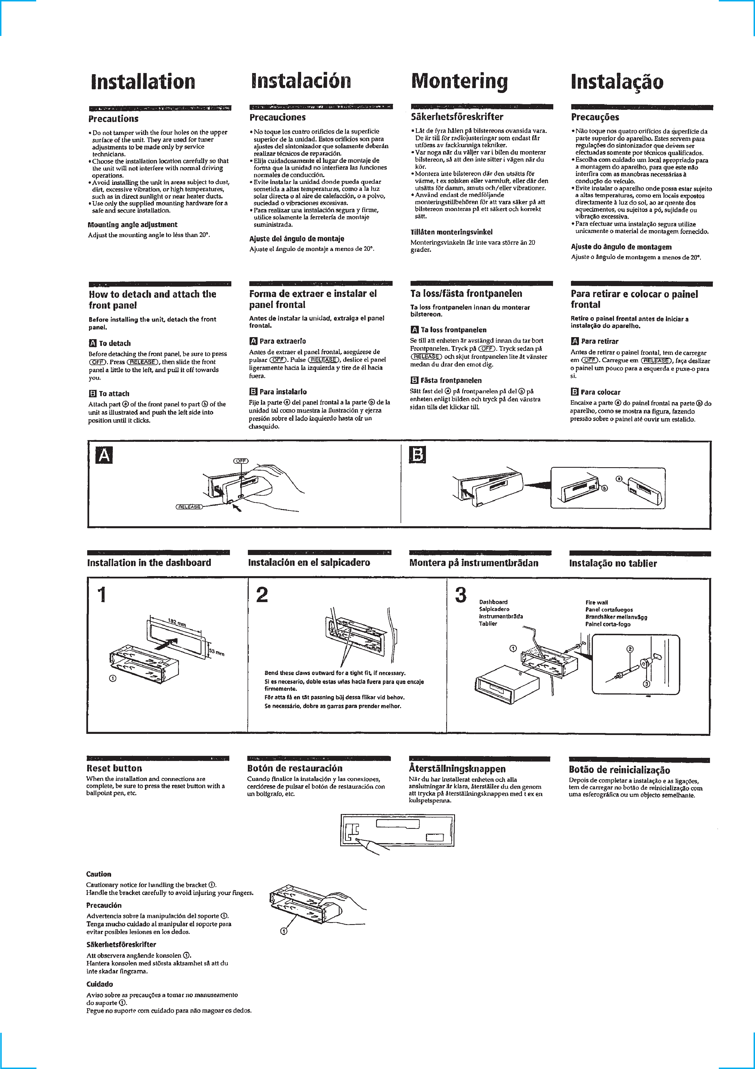
Installation .......................................................................
5
Connections .....................................................................
6
2.
DISASSEMBLY ......................................................... 10
3.
ASSEMBLY OF MECHANISM DECK ........... 11
4.
MECHANICAL ADJUSTMENTS ....................... 14
5.
ELECTRICAL ADJUSTMENTS ......................... 14
6.
DIAGRAMS
6-1. Block Diagram TUNER Section .............................. 18
6-2. Block Diagram TAPE/MAIN Section ...................... 19
6-3. Block Diagram DISPLAY/KEY CONTROL/
BUS CONTROL/POWER SUPPLY Section .............. 20
6-4. Note for Printed Wiring Boards and
Schematic Diagrams ....................................................... 21
6-5. Printed Wiring Board
MAIN Board (Component Side) .............................. 22
6-6. Printed Wiring Board
MAIN Board (Conductor Side) ................................ 23
6-7. Schematic Diagram MAIN Board (1/3) ................... 24
6-8. Schematic Diagram MAIN Board (2/3) ................... 25
6-9. Schematic Diagram MAIN Board (3/3) ................... 26
6-10. Printed Wiring Board KEY Board ........................... 30
6-11. Schematic Diagram KEY Board ............................. 31
6-12. IC Pin Function Description ........................................... 32
7.
EXPLODED VIEWS ................................................ 35
8.
ELECTRICAL PARTS LIST ............................... 38
Flexible Circuit Board Repairing
· Keep the temperature of the soldering iron around 270 °C dur-
ing repairing.
· Do not touch the soldering iron on the same conductor of the
circuit board (within 3 times).
· Be careful not to apply force on the conductor when soldering
or unsoldering.
Notes on chip component replacement
· Never reuse a disconnected chip component.
· Notice that the minus side of a tantalum capacitor may be dam-
aged by heat.
3
SECTION 1
GENERAL
This section is extracted from
instruction manual.
4
5