SERVICE MANUAL
FM/MW/LW CASSETTE CAR STEREO
UK Model
Model Name Using Similar Mechanism
XR-1800R
Tape Transport Mechanism Type
MG-36SZ9-32
SPECIFICATIONS
XR-1800RD
Cassette player section
Tape track
4-track 2-channel stereo
Wow and flutter
0.13 % (WRMS)
Frequency response
30 15,000 Hz
Signal-to- noise ratio
55 dB
Tuner section
FM
Tuning range
87.5 108.0 MHz
Aerial terminal
External aerial connector
Intermediate frequency
10.7 MHz
Usable sensitivity
9 dBf
Selectivity
75 dB at 400 kHz
Signal-to-noise ratio
65 dB (stereo),
68 dB (mono)
Harmonic distortion at 1 kHz
0.7% (stereo),
0.4% (mono)
Separation
35 dB at 1 kHz
Frequency response
30 15,000 Hz
MW/LW
Tuning range
MW:531 1,602 kHz
LW:153 281 kHz
Aerial terminal
External aerial connector
Intermediate frequency
450 kHz
Sensitivity
MW:30
µV
LW:50
µV
Power amplifier section
Outputs
Speaker outputs
(sure seal connectors)
Speaker impedance
4 8 ohms
8
Maximum power output 35 W
× 4 (at 4 ohms)
General
Output lead
Power aerial relay control
lead
Tone controls
Bass
±8 dB at 100 Hz
Treble
±8 dB at 10 kHz
Power requirements
12 V DC car battery
(negative ground)
Dimensions
Approx. 186
× 57 × 176 mm
(w/h/d) not incl.
projecting parts and
controls
Mounting dimension
Approx. 182
× 53 × 163 mm
(w/h/d) not incl.
projecting parts and
controls
Mass
Approx. 1.2 kg
Supplied accessories
Parts for installation and
connections (1 set)
Design and specifications are subject to change
without notice.

2
TABLE OF CONTENTS
1.
GENERAL
Button Locations .............................................................
3
Setting the Clock .............................................................
3
2.
DISASSEMBLY ......................................................... 4
3.
MECHANICAL ADJUSTMENTS ....................... 8
4.
ELECTRICAL ADJUSTMENTS
Tape Deck Section ..........................................................
8
Tuner Section ..................................................................
9
5.
DIAGRAMS
5-1. Note for Printed Wiring Boards and
Schematic Diagrams ....................................................... 13
5-2. Printed Wiring Board MAIN Board ........................ 15
5-3. Schematic Diagram MAIN Board (1/2) .................. 16
5-4. Schematic Diagram MAIN Board (2/2) .................. 17
5-5. Printed Wiring Board KEY Board ........................... 18
5-6. Schematic Diagram KEY Board ............................. 19
5-7. IC Pin Function Description ........................................... 21
6.
EXPLODED VIEWS ................................................ 23
7.
ELECTRICAL PARTS LIST ............................... 29
Flexible Circuit Board Repairing
· Keep the temperature of the soldering iron around 270 °C dur-
ing repairing.
· Do not touch the soldering iron on the same conductor of the
circuit board (within 3 times).
· Be careful not to apply force on the conductor when soldering
or unsoldering.
Notes on chip component replacement
· Never reuse a disconnected chip component.
· Notice that the minus side of a tantalum capacitor may be dam-
aged by heat.
3
SECTION 1
GENERAL
This section is extracted from
instruction manual.
EN
4
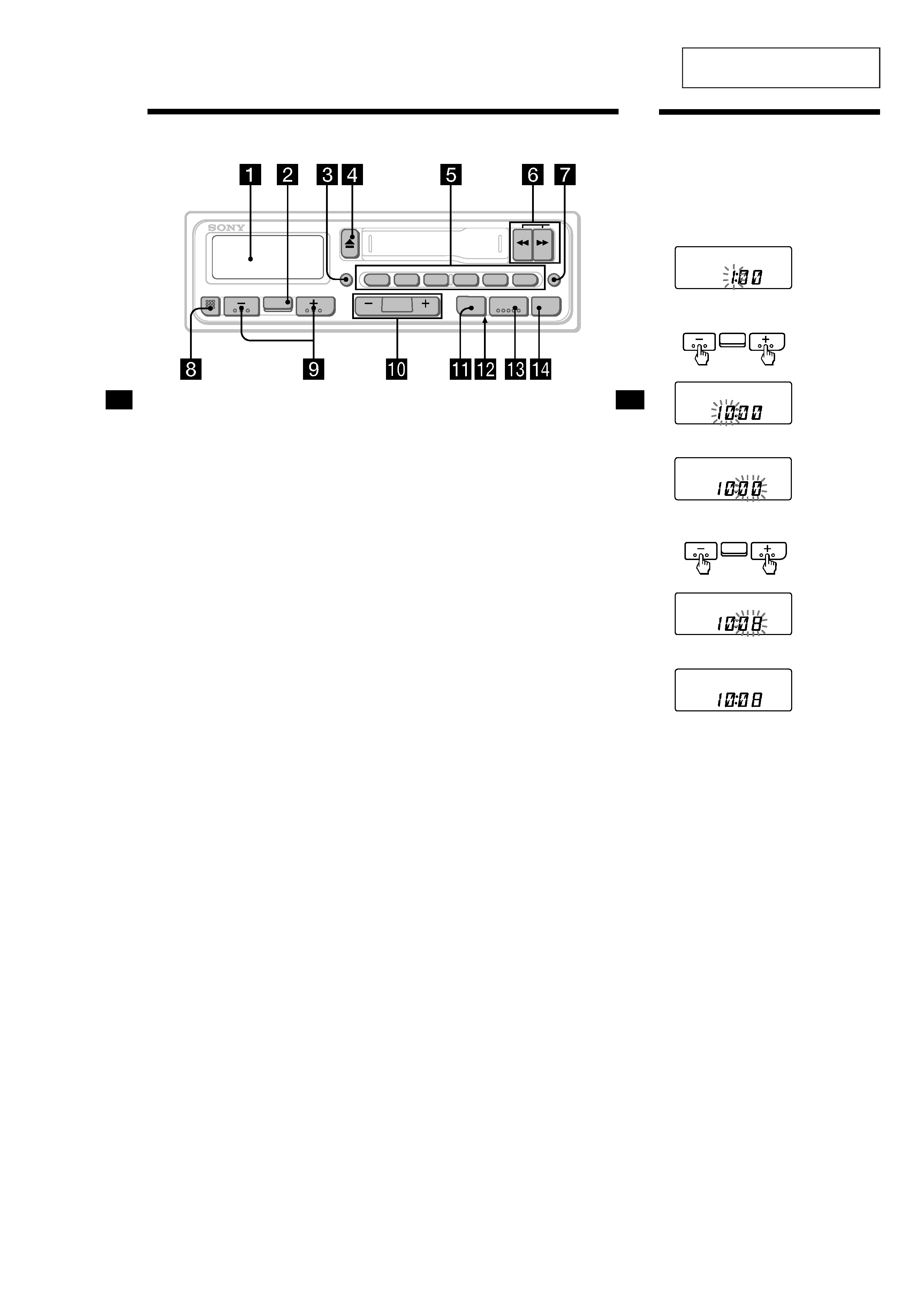
Button locations
8 RELEASE (front panel release) button
5, 15
9 (--)(+) (volume/bass/treble/balance/
fader control) buttons 6, 14
0 SEEK/MANU button 7, 8, 10, 13
qa PTY/LOUD (Programme type/loudness)
button 13, 14
qs Reset button (located on the front side
of the unit hidden by the front panel) 5
Press this button when you use this unit
for the first time, when you have changed
the car battery, or when the buttons of this
unit do not function properly.
qd TUNER/BTM(radio on
· band select/Best
tuning memory function) button 7, 8, 9,
12
qf OFF button 5
Refer to the pages for further details.
1 Display window
2 SEL (control mode select) button 6, 11,
13, 14
3 DSPL (display mode change/time set)
button 6, 10
4 Z (eject) button 6
5 During radio reception:
Preset number buttons 8, 9, 11, 12
During tape playback:
(1)
ATA (Automatic Tuner Activation)
button 7
6 m/M (fast winding)/DIR (tape
transport direction change) buttons 6, 7
7 AF/TA (alternative frequency/traffic
announcement) button 10, 11, 12
RELEASE
DSPL
ATA
TUNER
OFF
SEEK
MANU
AF/TA
BTM
DIR
2
13
6
4
5
XR-1800R
SEL
PTY
LOUD
EN
6
(to go back)
(to go forward)
Setting the clock
The clock has a 24-hour digital indication.
For example, setting it to 10:08
1 Display the time.
(Press (DSPL) during unit operation.)
2 Press (DSPL) for more than two seconds.
The hour digit blinks.
Set the hour digits.
3 Press the (SEL) button momentarily.
The minute digits blink.
Set the minute digits.
4 Press (DSPL) momentarily.
The clock starts.
Note
The clock cannot be set unless the power is turned
on. Set the clock after you turn on the radio, or
during tape playback.
(to go back)
(to go forward)
4
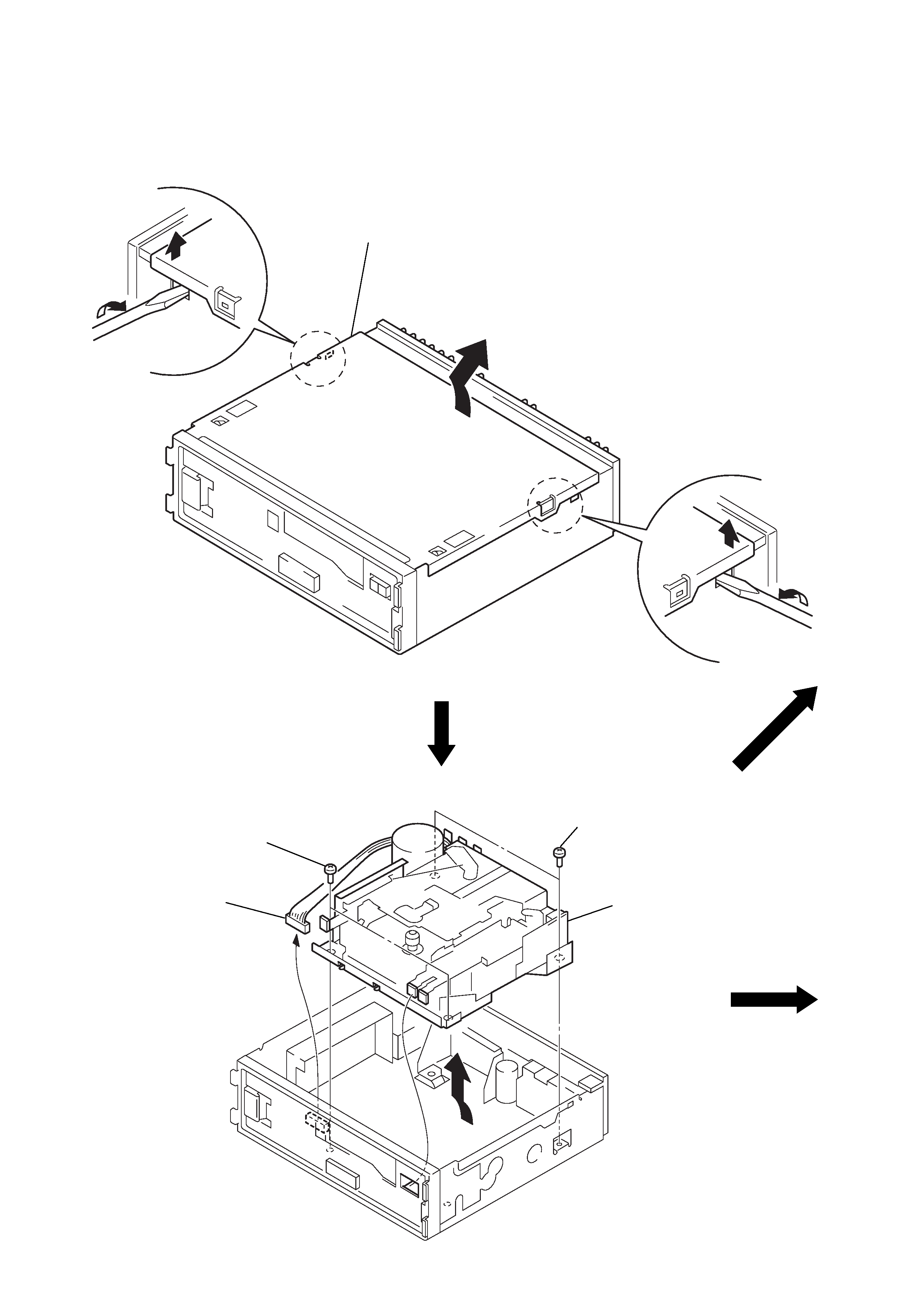
Note: Follow the disassembly procedure in the numerical order given.
SECTION 2
DISASSEMBLY
COVER ASSY
MECHANISM DECK BLOCK
3
cover assy
2
2
1
1
1
two screws
(PTT2.6
× 6)
3
mechanism deck block
1
two screws
(PTT2.6
× 6)
2
connector
(CN901)
5
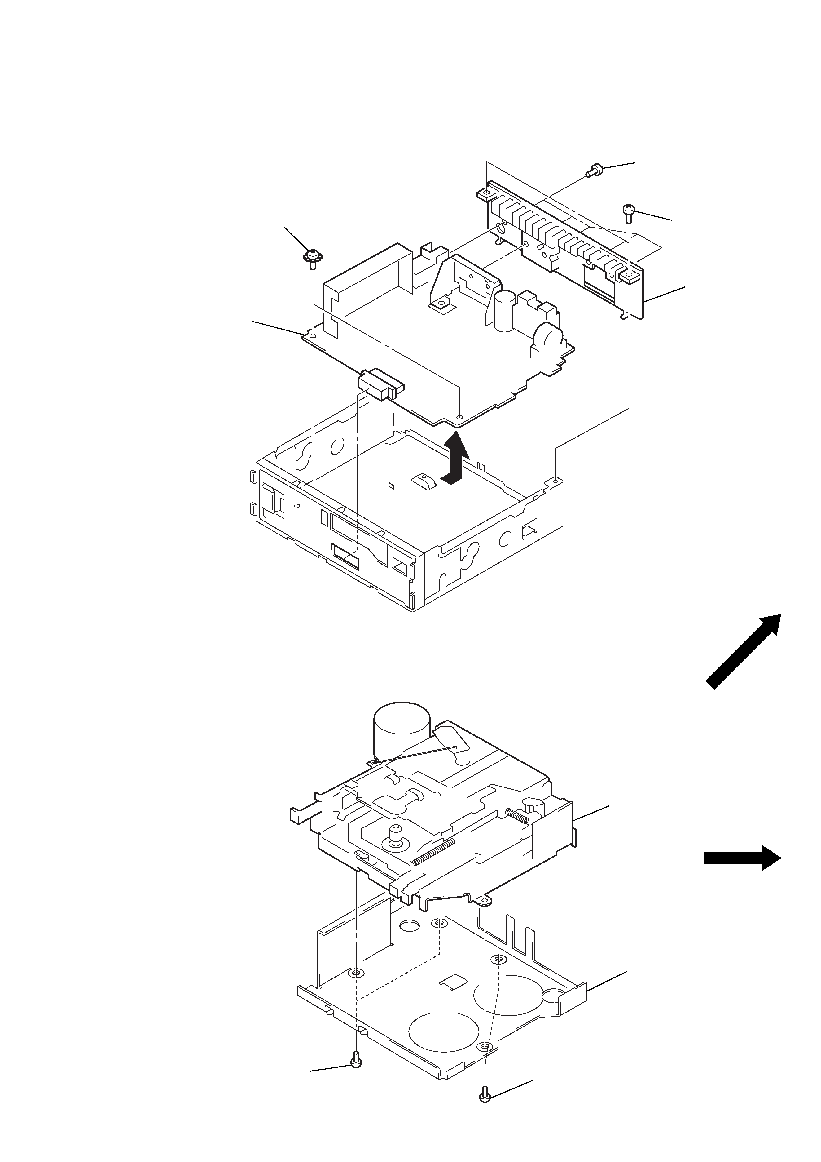
MAIN BOARD, HEAT SINK
MECHANISM DECK
(MG-36SZ9-32)
1
two screws
(PTT2.6
× 6)
5
heat sink
2
two screws
(ground point)
3
main board
4
five screws
(PTT2.6
× 8)
1
two screws
(P2.6
× 4)
3
mechanism deck
(MG-36SZ9-32)
1
two screws
(P2.6
× 4)
2
bracket (MD)