SERVICE MANUAL
9-870-060-13
Sony Corporation
2004I05-1
e Vehicle Company
© 2004.09
Published by Sony Engineering Corporation
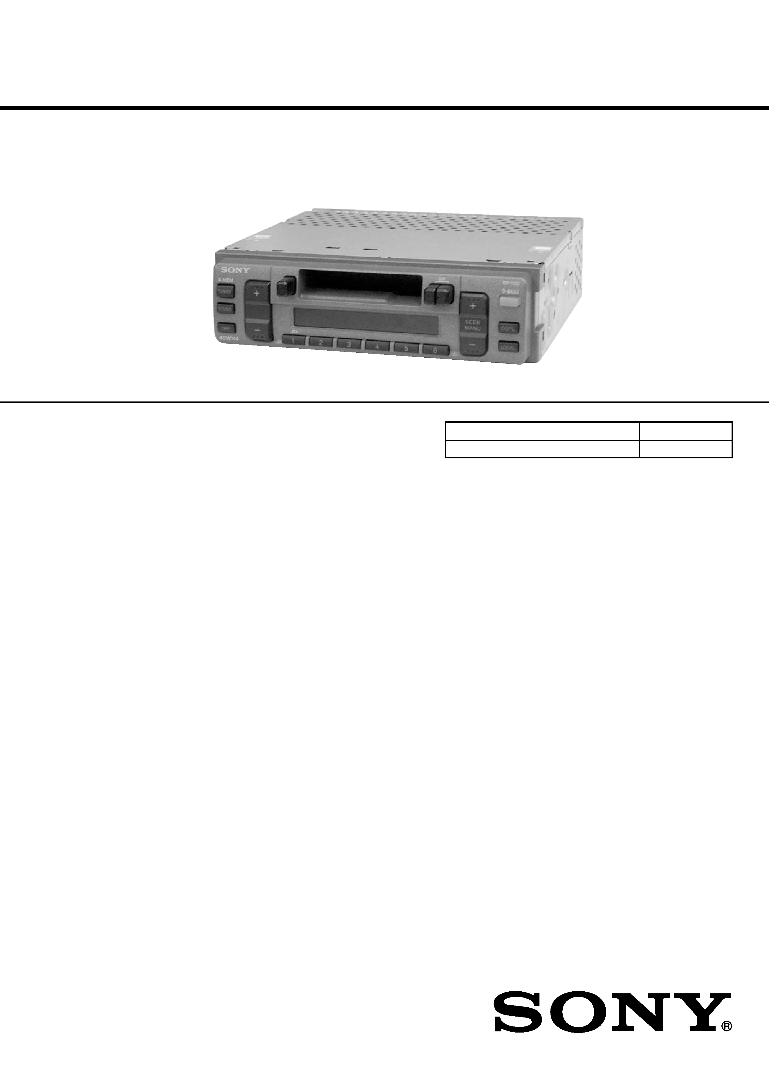
FM/AM CASSETTE CAR STEREO
US Model
Canadian Model
UK Model
E Model
SPECIFICATIONS
XR-1100
Model Name Using Similar Mechanism NEW
Tape Transport Mechanism Type
MG-36SZ10-32
Cassette player section
Tape track
4-track 2-channel stereo
Wow and flutter
0.13 % (WRMS)
Frequency response
30 15,000 Hz
Signal-to- noise ratio
55 dB
Tuner section
FM
Tuning range
US and Canadian models : 87.5 107.9 MHz
Antenna terminal
External antenna connector
E and UK models:
E and UK models:
FM tuning interval :
50kHz/ 200kHz
switchable
87.5 -108.0MHz
(at 50 kHz step)
87.5 -107.9 MHz
(at 200 kHz step)
Intermediate frequency
10.7 MHz
Usable sensitivity
9 dBf
Selectivity
75 dB at 400 kHz
Signal-to-noise ratio
65 dB (stereo),
68 dB (mono)
Harmonic distortion at 1 kHz
0.7% (stereo),
0.4% (mono)
Separation
35 dB at 1 kHz
Frequency response
30 15,000 Hz
AM
Tuning range
530 1,710 kHz
Antenna terminal
External antenna connector
Intermediate frequency
10.71 MHz/450 kHz
Sensitivity
30
µV
Power amplifier section
Outputs
Speaker outputs
(sure seal connectors)
Speaker impedance
4 8 ohms
Maximum power output 45 W
× 4 (at 4 ohms)
AUDIO POWER SPECIFICATIONS (US model only)
POWER OUTPUT AND TOTAL HARMONIC DISTORTION
17 watts per channel minimum continuous average power into
4 ohms, 4 channels driven from 20 Hz to 20 kHz with no more than
1% total harmonic distortion.
US and Canadian models :
AM tuning interval:
9 kHz/10 kHz switchable
531 1,602 kHz
(at 9 kHz step)
530 1,710 kHz
(at 10 kHz step)
Continued on next page
Ver 1.2 2004.09

2
XR-1100
TABLE OF CONTENTS
1.
GENERAL
Location of Controls .......................................................
3
Setting the Clock .............................................................
3
Installation .......................................................................
4
Connections .....................................................................
6
2.
DISASSEMBLY
2-1. Disassembly Flow ...........................................................
8
2-2. Front Panel Assy .............................................................
9
2-3. Mechanism Deck (MG-36SZ10-32) ...............................
9
2-4. MAIN board .................................................................... 10
2-5. Heat Sink ......................................................................... 10
2-6. Bracket (MD) .................................................................. 11
2-7. Motor (Capstan/Reel) (M901) ........................................ 11
2-8. Head (Play Back) (HP901) ............................................. 12
2-9. Main Belt, Sub Belt (C) .................................................. 13
3.
MECHANICAL ADJUSTMENTS ....................... 14
4.
ELECTRICAL ADJUSTMENTS
Tape Deck Section .......................................................... 14
Tuner Section .................................................................. 15
5.
DIAGRAMS
5-1. Note for Printed Wiring Boards and
Schematic Diagrams ....................................................... 18
5-2. Printed Wiring Board MAIN Board ........................ 19
5-3. Schematic Diagram MAIN Board (1/2) .................. 20
5-4. Schematic Diagram MAIN Board (2/2) .................. 21
5-5. Printed Wiring Board CONTROL Board ................ 22
5-6. Schematic Diagram CONTROL Board ................... 23
5-7. IC Pin Function Description ........................................... 25
6.
EXPLODED VIEWS
6-1. General Section ............................................................... 27
6-2. Front Panel Section ......................................................... 28
6-3. Mechanism Deck Section (MG-36SZ10-32) ................. 29
7.
ELECTRICAL PARTS LIST ............................... 30
Flexible Circuit Board Repairing
· Keep the temperature of the soldering iron around 270 °C dur-
ing repairing.
· Do not touch the soldering iron on the same conductor of the
circuit board (within 3 times).
· Be careful not to apply force on the conductor when soldering
or unsoldering.
Notes on chip component replacement
· Never reuse a disconnected chip component.
· Notice that the minus side of a tantalum capacitor may be dam-
aged by heat.
General
Outputlead
Power antenna relay
control lead
Tone controls
Bass
±8 dB at 100
Treble
±8 dB at 10 kHz
Power requirements
12 V DC car battery
(negative ground)
Dimensions
Approx. 188
× 58 ×177 mm
(7 /
× 2 / × 7 in.)
1
2
3
8
(w/h/d) not incl.
projecting parts and
controls
Mounting dimension
Approx. 182
× 53 × 163 mm
(7 /
× 2 / × 6 / in.)
1
4
1
8
1
2
(w/h/d) not incl.
projecting parts and
controls
Mass
Approx. 1.2 kg (2 lb. 10 oz.)
Supplied accessories
Parts for installation and
connections (1 set)
Design and specifications are subject to change
without notice.
3
XR-1100
SECTION 1
GENERAL
This section is extracted from
instruction manual.
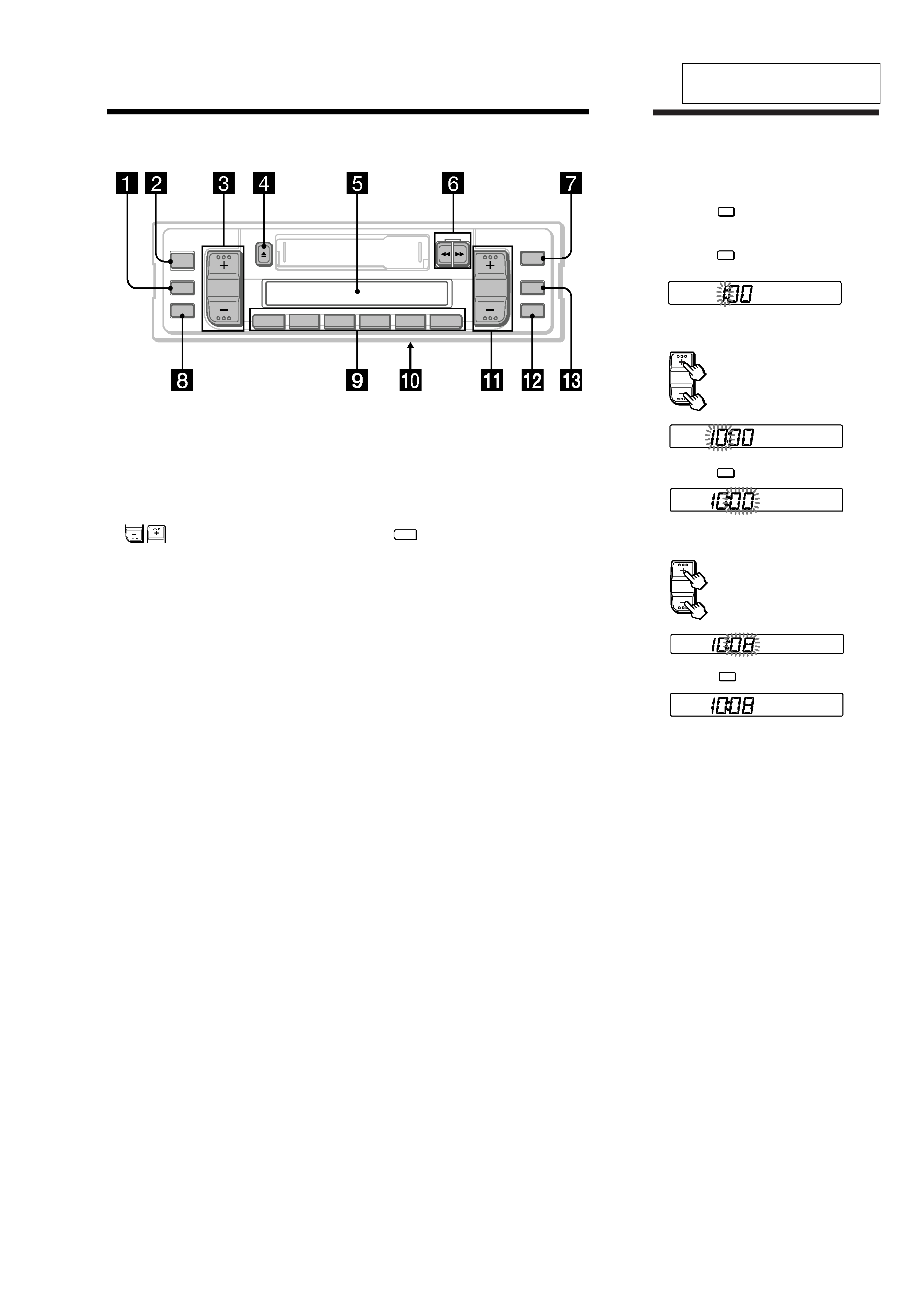
The clock activates.
4 Press the DSPL button momentarily.
Note
The clock cannot be set unless the power is turned
on. Set the clock after you turn on the radio, or
during tape playback.
Setting the clock
The clock has a 12-hour digital indication.
For example, setting it to 10:08
1 Display the time.
(Press the DSPL button during unit
operation.)
2 Press the DSPL button for more than two
seconds.
Set the hour digits.
3 Press the SOUND button momentarily.
Set the minute digits.
to go forward
to go back
to go forward
to go back
The hour digit blinks.
The minute digits blink.
5
GB
Location of controls
Refer to the pages for further details.
1 SOUND (control mode select) button
6, 9, 10
2 TUNER/A MEM (radio on
· band select/
automatic memory) button 8, 9
3
(volume/bass/treble/balance/
fader control) buttons 6, 9
4 Z (eject) button 7
5 Display window
6 m/M (fast winding)/DIR (tape
transport direction change) buttons 7
D-BASS
DSPL
2
3456
1
LOCAL
SOUND
OFF
ATA
A MEM
TUNER
SEEK
MANU
XR-1100
DIR
7 D-BASS button 9
8 OFF button
9 During radio reception:
Preset number buttons 9
During tape playback:
1
ATA
(Automatic Tuner Activation)
button 7
q; Frequency select switch (located on the
bottom of the unit) (E and UK models only)
See "Frequency select switch" in the
Installation/Connections manual.
qa SEEK/MANU button 8
qs LOCAL (local seek) button 8
qd DSPL (display mode change/time set)
button 6
Ver 1.1 2001.06
4
XR-1100
182
mm
53 mm
Installation
Precautions
·Choose the installing location carefully so that
the unit will not interfere with driving.
·Avoid installing the unit where it would be
subject to high temperatures, such as direct
sunlight or hot air from the heater, or where it
would be subject to dust, dirt, or excessive
vibration.
·Use only the supplied mounting hardware for
safe and secure installation.
Mounting angle adjustment
Adjust the mounting angle to less than 20
°.
Installation
Précautions
·Choisir soigneusement l'emplacement de
l'installation, pour que l'appareil ne gêne pas
la conduite.
·Eviter d'installer l'appareil dans un endroit
exposé à des températures élevées, comme en
plein soleil ou à proximité d'une bouche d'air
chaud, ou dans un endroit exposé à de la
poussière, de la saleté ou des vibrations
violentes.
·Pour garantir un montage sûr, n'utiliser que le
matériel fourni.
Mounting the unit in a Japanese car
This unit may not be installed in some makes of cars. In this case, consult your nearest Sony dealer.
Installation de l'appareil dans une voiture japonaise
Cet appareil ne peut pas être installé dans certaines voitures. Consultez, dans ce cas, votre revendeur
Sony.
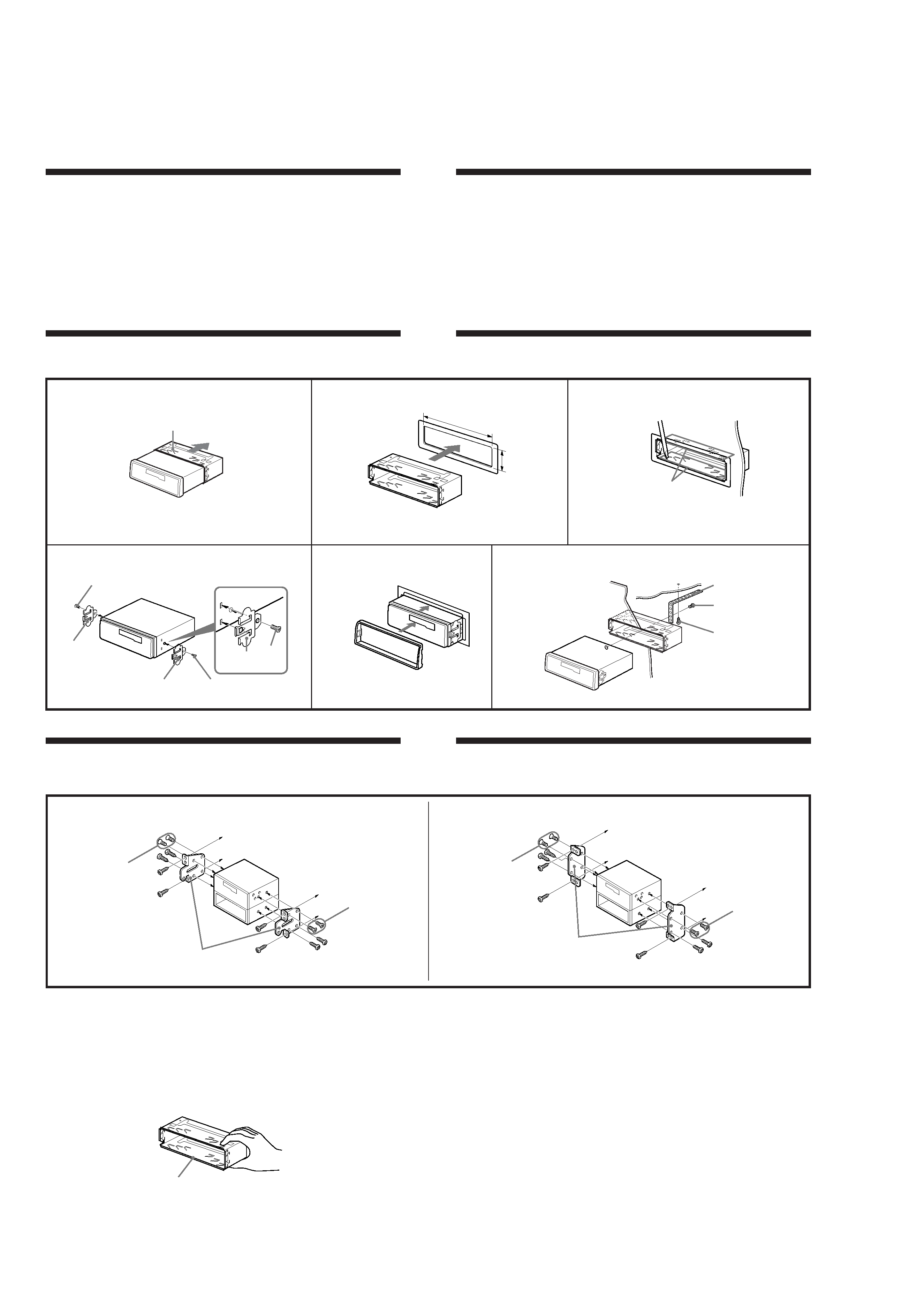
Mounting example
Installing in the dashboard
Exemple de montage
Installation dans le tableau de bord
Note
To prevent malfunction, install only with the supplied screws 7.
Réglage de l'angle de montage
Ajuster l'inclinaison à un angle inférieur à 20
°.
Remarque
Pour éviter tout mauvais fonctionnement, utilisez uniquement les vis fournies 7 pour le montage.
1
3
2
Bend these claws, if necessary.
Courbez les griffes en cas de
besoin.
5
3
1
2
Dashboard
Tableau de bord
Fire wall
Paroi ignifuge
4
7
7
6
7
6
7
5
To support the unit
Pour soutenir l'appareil
Remove the bracket.
Enlevez le support.
1
Bracket
Support
to dashboard/center console
au tableau de bord/console centrale
to dashboard/center console
au tableau de bord/console centrale
Bracket
Support
TOYOTA
NISSAN
7
max. size ø5
× 8 mm
Dimension max.
ø5
× 8 mm
7
max. size ø5
× 8 mm
Dimension max.
ø5
× 8 mm
7
max. size ø5
× 8 mm
Dimension max.
ø5
× 8 mm
7
max. size ø5
× 8 mm
Dimension max.
ø5
× 8 mm
1
4
(US and Canadian models)
Caution
Cautionary notice for handling the bracket 1.
Handle the bracket carefully to avoid injuring
your fingers.
Attention
Remarque importante pour la manipulation du
support 1.
Manipulez précautionneusement le support
pour éviter de vous blesser aux doigts.
1
5
XR-1100
182 m
m
53 m
m
Installation
Precautions
·Choose the installing location carefully so that the unit will not
interfere with the normal driving functions of the driver.
·Avoid installing the unit where it would be subject to high
temperatures, such as from direct sunlight or hot air from the
heater, or where it would be subject to dust, dirt or excessive
vibration.
·Use only the supplied mounting hardware for a safe and secure
installation.
Mounting angle adjustment
Adjust the mounting angle to less than 20
°.
Instalación
Precauciones
·Elija cuidadosamente el lugar de instalación de forma que la
unidad no impida la conducción.
·Evite instalar la unidad donde pueda quedar sometida a altas
temperaturas, como a la luz solar directa o al aire caliente de
calefacción, o a polvo, suciedad, o vibraciones excesivas.
·Para realizar una instalación segura y firme, emplee solamente la
ferretería de montaje suministrada.
Ajuste del ángulo de montaje
Ajuste el ángulo de montaje a menos de 20
°.
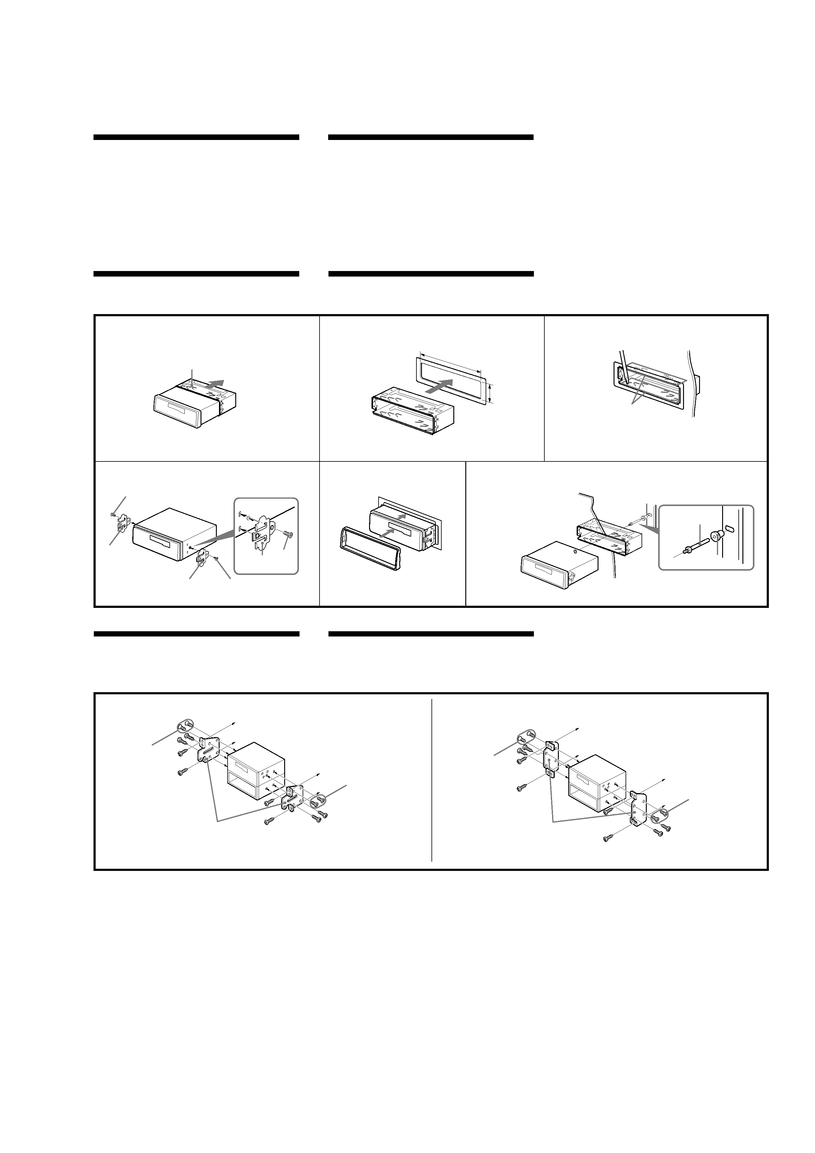
Mounting example
Installing in the dashboard
Ejemplo de montaje
Instalación en el salpicadero
Bend these claws, if necessary.
Si es necesario, doble estas pestañas.
5
3
1
2
1
Dashboard
Salpicadero
Fire wall
Panel cortafuegos
4
5
6
4
Remove the bracket.
Retire el soporte.
To support the unit
Sujeción de la unidad
1
Mounting the unit in a Japanese car
You may not be able to install this unit in some makes of Japanese
cars. In such a case, consult your Sony dealer.
Montaje de la unidad en un automóvil
japonés
Usted no podrá instalar esta unidad en algunos automóviles
japoneses. En tal caso, consulte a su proveedor Sony.
6
5
5
6
2
3
NISSAN
TOYOTA
to dashboard/center console
al salpicadero/consola central
to dashboard/center console
al salpicadero/consola central
Bracket
Soporte
6
max. size
ø 5
× 8 mm
Tamaño máx.
ø 5
× 8 mm
Bracket
Soporte
6
max. size
ø 5
× 8 mm
Tamaño máx.
ø 5
× 8 mm
6
max. size
ø 5
× 8 mm
Tamaño máx.
ø 5
× 8 mm
6
max. size
ø 5
× 8 mm
Tamaño máx.
ø 5
× 8 mm
1
Note
To prevent malfunction, install only with the supplied screws 6.
Nota
Para evitar que se produzcan fallos, realice la instalación solamente con
los tornillos suministrados 6.
(E and UK models)
Ver 1.1 2001.06