1
Other Specifications
Circuit system
Class D Technology
Pulse power supply
Inputs
RCA pin jacks
High level input connector
Outputs
Speaker terminals
Through out pin jacks
Suitable speaker impedance
2 8
Maximum outputs
600 W (at 4
)
1,100 W (at 2
)
Rated outputs (supply voltage at 14.4 V)
250 W (20 Hz 300 Hz, 0.2% THD, at 4
)
500 W (20 Hz 300 Hz, 0.6% THD, at 2
)
Frequency response
5 Hz 300 Hz (
dB)
Harmonic distortion
0.04% or less (at 100 Hz, 4
)
Input level adjustment range
0.3 6.0 V (RCA pin jacks)
1.2 12.0 V (High level input)
SERVICE MANUAL
US Model
Canadian Model
AEP Model
UK Model
E Model
XM-D500X
MONAURAL POWER AMPLIFIER
Low-pass filter
50 300 Hz, 12 dB/oct
Low boost
0 10 dB (40 Hz)
Power requirements
12 V DC car battery
(negative ground)
Power supply voltage
10.5 16 V
Current drain
at rated output : 50 A (at 2
)
Remote input : 2 mA
Dimensions
Approx. 388
× 53 × 268 mm
(15 3/8
× 2 1/8 × 10 1/8 in.) (w/h/d) not incl.
projecting parts and controls
Mass
Approx. 3.3 kg (7 lb. 5 oz.) not incl. accessories
Supplied accessories
Mounting screws (4)
High level input cord (1)
Protection cap (1)
Design and specifications are subject to change without
notice.
SPECIFICATIONS
AUDIO POWER SPECIFICATIONS (US MODEL)
POWER OUTPUT AND TOTAL HARMONIC DISTORTION
250 watts minimum continuous average power into 4 ohms, 20 Hz to
300 Hz with no more than 0.2% total harmonic distortion per Car
Audio Ad Hoc Committee standards.
+0.5
3
Notes on Chip Component Replacement
· Never reuse a disconnected chip component.
· Notice that the minus side of a tantalum capacitor may be
damaged by heat.
Ver 1.0 2004. 01
Sony Corporation
e Vehicle Company
Published by Sony Engineering Corporation
9-877-561-01
2004A04-1
© 2004. 01

2
TABLE OF CONTENTS
1. GENERAL
Location and Function of Controls .......................................... 3
Connections ............................................................................. 4
2. DISASSEMBLY
2-1. Bottom Plate ........................................................................ 7
2-2. Main Board Section, LED Board ........................................ 8
2-3. Main Board .......................................................................... 8
3. DIAGRAMS
3-1. Note for Printed Wiring Board and Schematic Diagram ..... 9
3-2. IC Block Diagram ................................................................ 9
3-3. Printed Wiring Boards Main Section ............................. 10
3-4. Schematic Diagram Main Section (1/2) ........................ 12
3-5. Schematic Diagram Main Section (2/2) ........................ 13
4. EXPLODED VIEWS
4-1. Heat Sink (Main) Section .................................................. 15
4-2. Main Board Section ........................................................... 16
5. ELECTRICAL PARTS LIST ......................................... 17
XM-D500X
SAFETY-RELATED COMPONENT WARNING!!
COMPONENTS IDENTIFIED BY MARK 0 OR DOTTED LINE
WITH MARK 0 ON THE SCHEMATIC DIAGRAMS AND IN
THE PARTS LIST ARE CRITICAL TO SAFE OPERATION.
REPLACE THESE COMPONENTS WITH SONY PARTS WHOSE
PART NUMBERS APPEAR AS SHOWN IN THIS MANUAL OR
IN SUPPLEMENTS PUBLISHED BY SONY.
ATTENTION AU COMPOSANT AYANT RAPPORT
À LA SÉCURITÉ!!
LES COMPOSANTS IDENTIFIÉS PAR UNE MARQUE 0 SUR LES
DIAGRAMMES SCHÉMATIQUES ET LA LISTE DES PIÈCES SONT
CRITIQUES POUR LA SÉCURITÉ DE FONCTIONNEMENT. NE
REMPLACER CES COMPOSANTS QUE PAR DES PIÈCES SONY
DONT LES NUMÉROS SONT DONNÉS DANS CE MANUEL OU
DANS LES SUPPLÉMENTS PUBLIÉS PAR SONY.
3
XM-D500X
SECTION 1
GENERAL
This section is extracted
from instruction manual.
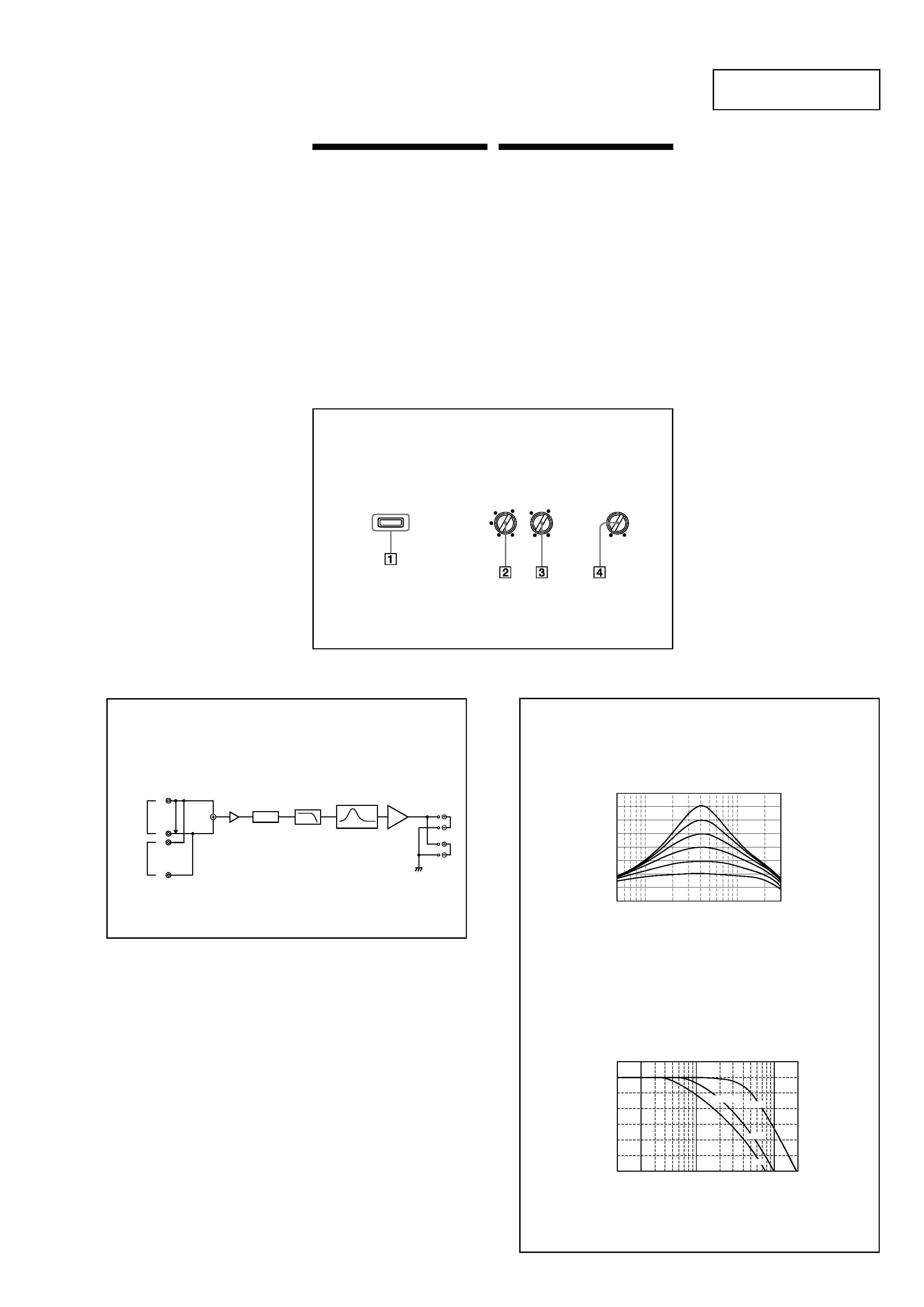
Location and Function
of Controls
1
POWER/PROTECTOR indicator
Lights up in green during operation.
When the PROTECTOR is activated the
indicator will change from green to red.
When the PROTECTOR is activated refer to
the TroubleShooting Guide.
2
LEVEL adjustment control
The input level can be adjusted with this
control. Turn it in the clockwise direction
when the output level of the car audio unit
seemslow.
3
Cut-off frequency adjustment control
Setsthe cut-off frequency (50 300Hz) for
the low-pass filters.
4
LOW BOOST level control
Turn this control to boost the frequencies
around 40 Hz to a maximum of 10 dB.
Emplacement et
fonction des
commandes
1
Indicateur POWER/PROTECTOR
S'allume en vert en cours de fonctionnement.
Lorsque PROTECTOR est activé, le voyant
passedu vert au rouge.
Lorsque PROTECTOR est activé, reportez-
vous au guide de dépannage.
2
Commande de réglage LEVEL
Le niveau d'entrée peut se régler avec cette
commande. Tournez cette commande dans le
sensdes aiguilles d'une montre lorsque le
niveau de sortie de l'auto-radio semble faible.
3
Commandes de réglage de la fréquence de
coupure
Règle la fréquence de coupure (50 300Hz)
pour les filtres passe-bas.
4
Commande de niveau LOW BOOST
Tournez cette commande pour amplifier les
fréquencesautour de 40 Hz à un maximum
de 10 dB.
POWER/PROTECTOR
LEVEL
0+10dB
LPF
50
300Hz
6
2
4
0.3V
0.5
70
100
LOW BOOST
(40Hz)
LEVEL
Buffer
AMP
Power
Lch
INPUT
THROUGH
OUT
Rch
Lch
Rch
LOW BOOST
LPF
Block Diagram
Schéma fonctionnel
10
0
510
40
100
300
10
0
-10
-20
-30
-40
-50
-60
10
100
1k
2k
50Hz
LOW PASS
100Hz
300Hz
dB
dB
Hz
Low boost
Amplification de basses fréquences
Low Pass Filter
Filtre passe-bas
Frequency/Fréquence
Hz
Frequency/Fréquence
4
XM-D500X
Connections
Caution
· Before making any connections, disconnect
the ground terminal of the car battery to avoid
short circuits.
· Be sure to use speakerswith an adequate
power rating. If you use small capacity
speakers,they may be damaged.
· Do not connect the # terminal of the speaker
system to the car chassis.
· Install the input and output cords away from
the power supply wire as running them close
together can generate some interference noise.
· This unit is a high powered amplifier.
Therefore, it may not perform to its full
potential if used with the speaker cords
supplied with the car.
· If your car is equipped with a computer
system for navigation or some other purpose,
do not remove the ground wire from the car
battery. If you disconnect the wire, the
computer memory may be erased.To avoid
short circuits when making connections,
disconnect the +12 V power supply wire until
all the other wires have been connected.
Connexions
Attention
· Avant d'effectuer les connexions, débranchez
la borne de massede la batterie de voiture
pour éviter tout court-circuit.
· Veillez à utiliser des haut-parleurs de
puissance adéquate. Si vous utilisez des haut-
parleurs de faible capacité,ils risquent d'être
endommagés.
· Ne raccordez pas la borne # du systèmede
haut-parleurs à la carrosserie de la voiture.
· Eloignez les câblesd'entrée et de sortie du
câble d'alimentation pour éviter les
interférences.
· Cet appareil est un amplificateur de haute
puissance.Il ne peut donc déployer sa pleine
puissance que si les câblesde haut-parleurs de
la voiture lui sont raccordés.
· Si votre voiture est équipée d'un systèmede
navigation ou de tout autre type d'ordinateur
de bord, ne retirez pas le câble de massede la
batterie de la voiture. Pour éviter un court-
circuit lorsque vous effectuez les
branchements, branchez le câble
d'alimentation +12 V après avoir branché tous
les autres câbles.
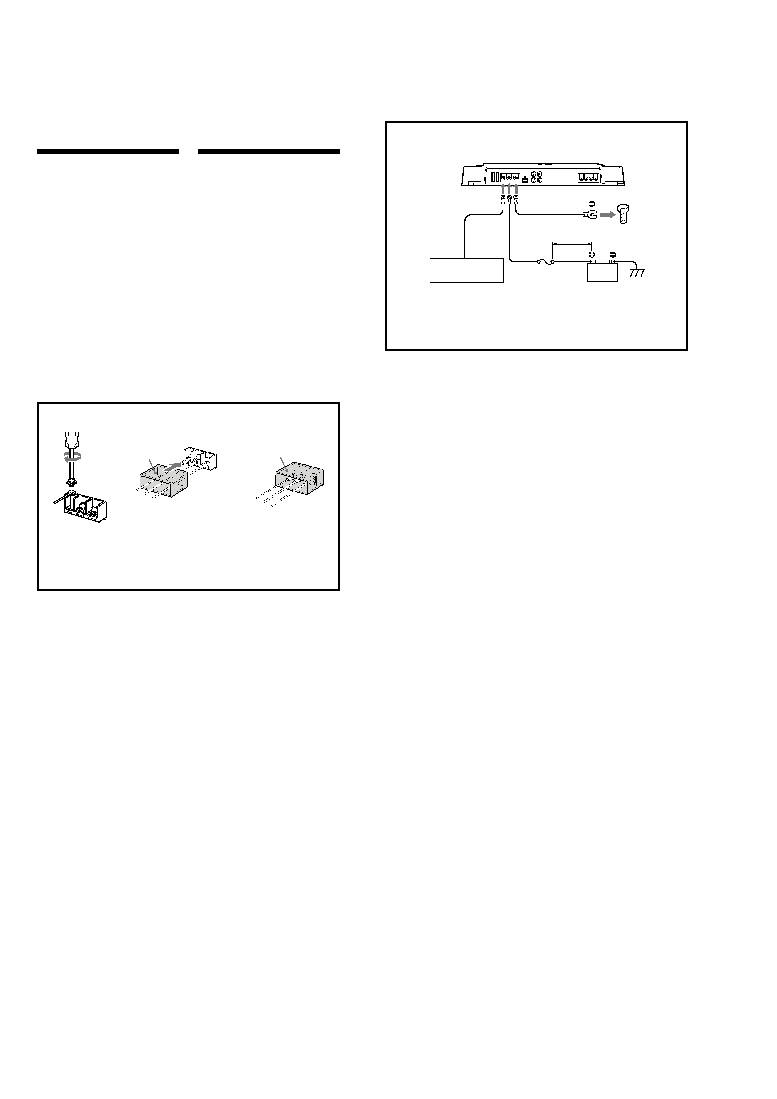
Make the terminal connections as illustrated below.
Effectuez les connexions des bornes comme illustré ci-dessous.
REM
+12V
GND
REM
+12V
GND
Pass the wires through the cap, connect
the wires, then cover the terminals with
the cap.
Note
When you tighten the screw, be careful not to
apply too much torque * as doing so may damage
the screw.
* The torque value should be less than 1 N·m.
Faites passer les câbles par le cache,
raccordez les câbles, puis recouvrez les
bornes avec le cache.
Remarque
Lorsque vous vissez la vis, faites attention à ne
pas appliquer une trop grande force de torsion *,
car cela pourrait endommager la vis.
* Le couple de torsion doit être inférieur à 1 N·m.
c
3
3
Power Connection Wires
Câbles d'alimentation
Car audio unit
Autoradio
Fuse (80 A)
Fusible (80 A)
+12 V car battery
Batterie de voiture +12 V
to a metal point
of the car
vers une partie
métallique de la
carrosserie
less than 450 mm (18 in.)
moins de 450 mm (18 po)
*2
Remote output *1
Sortie de
télécommande *1
(REM OUT)
*
1
If you have the factory original or some other car audio without a remote output for the amplifier,
connect the remote input terminal (REMOTE) to the accessory power supply.
*
1
Si vous disposez du modèle d'origine ou d'un autre auto-radio sans aucune sortie de télécommande
pour l'amplificateur,
raccordez la borne d'entrée de la télécommande (REMOTE)à la prise
d'alimentation
accessoires.
Notes on the power supply
·
Connect the +12 V power supply wire only after
all the other wires have been connected.
·
Be sure to connect the ground wire of the unit
securely to a metal point of the car. A loose
connection may cause a malfunction of the
amplifier.
·
Be sure to connect the remote control wire of the
car audio to the remote terminal.
· When using a car audio without a remote output
on the amplifier, connect the remote input
terminal (REMOTE)to the accessorypower supply.
·
Use the power supply wire with a fuse attached
(80 A).
·
All power wires connected to the positive battery
post should be fused within 450 mm (18 in.) of
the battery post, and before they pass through
any metal.
·
Make sure that the vehicle's battery wires
connected to the vehicle (ground to chassis)*2 are
of a wire gauge at least equal to that of the main
power wire connected from the battery to the
amplifier.
·
Make sure that the wires to be connected to the
+12 V and GND terminals of this unit are at least
4-Gauge (AWG-4) or have a sectional area of
more than 22.0 mm 2 (7/8 in. 2).
Remarques sur l'alimentation électrique
·
Raccordez le câble d'alimentation
+12 V
uniquement après avoir réalisé toutes les autres
connexions.
·
Raccordez correctement le fil de masse à une
partie métallique de la voiture. Une connexion
lâche peut provoquer un dysfonctionnement de
l'amplificateur.
·
Veillez à raccorder le fil de télécommande de
l'auto-radio à la borne de télécommande.
·
Si vous utilisez un auto-radio dont l'amplificateur
ne comporte pas de sortie de télécommande,
raccordez la borne d'entrée de la télécommande
(REMOTE)à la prise d'alimentation
accessoires.
·
Utilisez un câble d'alimentation
muni d'un fusible
(80 A).
·
Tous les fils électriques raccordés au support de
batterie positif doivent être protégés par un
fusible à une distance maximum de 450 mm (18
po) du support de batterie et avant de passer
dans une partie métallique quelconque.
·
Assurez-vous que les fils de la batterie du véhicule
raccordés à ce dernier (sol au châssis) *2 sont d'un
calibre au moins égal à celui du fil électrique
principal reliant la batterie et l'amplificateur.
·
Assurez-vous que les câbles à raccorder aux
bornes +12V et GND de cet appareil sont d'un
calibre d'au moins 4 (AWG-4) ou d'une section
supérieure à 22,0 mm 2 (7/8 po 2).
5
XM-D500X
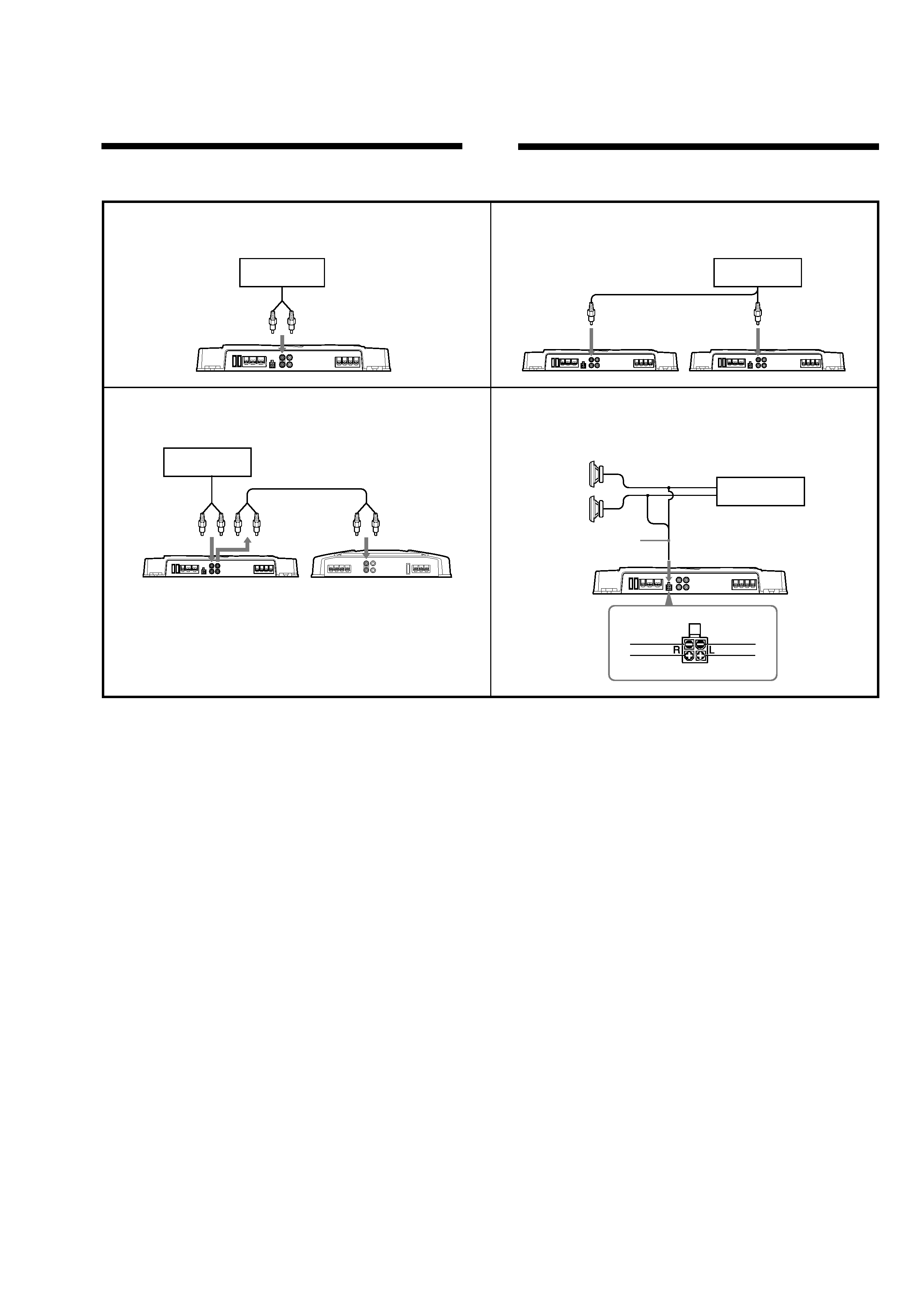
Input Connections
For details on the settings of switches and controls, refer to "Location and Function of Controls."
Connexions d'entrée
Pour plus de détails sur les réglages des commutateurs et commandes, reportez-vous à
« Emplacement et fonction des commandes ».
Line Input Connection (with Speaker Connection 1 or 2)
Connexion d'entrée de ligne (avec connexion de haut-
parleur 1 ou 2)
A
A
A
A
A
Line Input Connection (with Speaker Connection 3)
Connexion d'entrée de ligne (avec connexion de haut-
parleur 3)
B
B
B
B
B
Line Input Connection (with Speaker Connection 4)
Connexion d'entrée de ligne (avec connexion de haut-
parleur 4)
C
C
C
C
C
High Level Input Connection (with Speaker Connection
1
or 2)
Connexion à l'entrée de haut niveau (avec connexion
de haut-parleur 1 ou 2)
D
D
D
D
D
Car audio unit
Auto-radio
LINE OUT
Car audio unit
Auto-radio
LINE OUT
Right channel
Canal droit
Left channel
Canal gauche
Lorsque que vous raccordez des amplificateurs à
l'aide des prises à broches THROUGHOUT, vous
pouvez raccorder jusqu'à trois amplificateurs.
Sinon les niveaux de sortie requis ne peuvent pas
être obtenus et votre autoradio risque d'être
endommagé.
Utilisez la borne THROUGHOUT lorsque vous
installez plusieurs amplificateurs. Les signaux audio
transitent par les prises à broches THROUGHOUT
sans subir aucun traitement.
When you connect amplifiers using the THROUGH
OUT pin jacks, it allows you to connect up to a
maximum of three.
Otherwise the necessaryoutput levels can not be
obtained, and your car audio may be damaged.
Use the THROUGHOUT terminal when you install
more amplifiers. Audio signals pass through the
THROUGHOUT pin jacks unaffected by any signal
processing.
Car audio unit
Auto-radio
LINE OUT
THROUGH OUT
INPUT
INPUT
Car audio unit
Auto-radio
Left speaker
Haut-parleur gauche
Right speaker
Haut-parleur droit
Gray/Black striped
Rayé gris/noir
White/Black striped
Rayé blanc/noir
Gray
Gris
White
Blanc
2