1
SERVICE MANUAL
US Model
Canadian Model
AEP Model
UK Model
E Model
XM-2200GTX
STEREO POWER AMPLIFIER
Other Specifications
Circuit system
OTL (output transformerless) circuit
Pulse power supply
Inputs
RCA pin jacks
High level input connector
Outputs
Speaker terminals
Through out pin jacks
Suitable speaker impedance
2 8
(stereo)
4 8
(when used as a bridging amplifier)
Maximum outputs
400 W
× 2 (at 4 )
600 W
× 2 (at 2 )
1,200 W (monaural) at 4
Rated outputs (supply voltage at 14.4 V)
200 W
× 2 (20 Hz 20 kHz, 0.1% THD,
at 4
)
250 W
× 2 (20 Hz 20 kHz, 0.15% THD,
at 2
)
500 W (monaural) (20 Hz 20 kHz, 0.15% THD,
at 4
)
Frequency response
5 Hz 50 kHz (
dB)
Input level adjustment range
0.3 6.0 V (RCA pin jacks)
1.2 12.0 V (High level input)
Low-pass filter
50 300 Hz, 12 dB/oct
Low boost
0 10 dB (40 Hz)
Power requirements
12 V DC car battery
(negative ground)
Power supply voltage
10.5 16 V
Current drain
at rated output : 48 A (at 4
)
Remote input : 1 mA
Dimensions
Approx. 400
× 55 × 276 mm
(15 3/4
× 2 1/4 × 10 7/8 in.)
(w/h/d) not incl. projecting parts and controls
Mass
Approx. 4.6 kg (10 lb. 6 oz.) not incl. accessories
Supplied accessories
Mounting screws (4)
High level input cord (1)
Protection cap (1)
Design and specifications are subject to change without
notice.
SPECIFICATIONS
AUDIO POWER SPECIFICATIONS (US MODEL)
POWER OUTPUT AND TOTAL HARMONIC DISTORTION
200 watts per channel minimum continuous average power into
4 ohms, both channels driven from 20 Hz to 20 kHz with no more
than 0.1% total harmonic distortion per Car Audio Ad Hoc
Committee standards.
+0
3
Ver. 1.3 2005. 05
9-961-370-04
2005E04-1
© 2005. 05
Sony Corporation
e Vehicle Group
Published by Sony Engineering Corporation

2
TABLE OF CONTENTS
1. GENERAL
Location and Function of Controls .......................................... 3
Connections ............................................................................. 3
2. DISASSEMBLY
2-1. Bottom Plate ........................................................................ 7
2-2. Main Board Section ............................................................ 8
2-3. Main Board ......................................................................... 8
2-4. Led Board ............................................................................ 9
3. ELECTRICAL ADJUSTMENT .................................... 10
4. DIAGRAMS
4-1. Block Diagram .................................................................. 11
4-2. Schematic Diagram Main Section (1/2) ........................ 12
4-3. Schematic Diagram Main Section (2/2) ........................ 13
4-4. Printed Wiring Boards Main Section ............................ 14
5. EXPLODED VIEWS
5-1. Heat Sink (Main) Section .................................................. 16
5-2. Main Board Section .......................................................... 17
6. ELECTRICAL PARTS LIST ......................................... 18
Notes on Chip Component Replacement
· Never reuse a disconnected chip component.
· Notice that the minus side of a tantalum capacitor may be dam-
aged by heat.
SAFETY-RELATED COMPONENT WARNING!!
COMPONENTS IDENTIFIED BY MARK 0 OR DOTTED LINE
WITH MARK 0 ON THE SCHEMATIC DIAGRAMS AND IN
THE PARTS LIST ARE CRITICAL TO SAFE OPERATION.
REPLACE THESE COMPONENTS WITH SONY PARTS WHOSE
PART NUMBERS APPEAR AS SHOWN IN THIS MANUAL OR
IN SUPPLEMENTS PUBLISHED BY SONY.
ATTENTION AU COMPOSANT AYANT RAPPORT
À LA SÉCURITÉ!!
LES COMPOSANTS IDENTIFIÉS PAR UNE MARQUE 0 SUR LES
DIAGRAMMES SCHÉMATIQUES ET LA LISTE DES PIÈCES
SONT CRITIQUES POUR LA SÉCURITÉ DE FONCTIONNEMENT.
NE REMPLACER CES COMPOSANTS QUE PAR DES PIÈCES
SONY DONT LES NUMÉROS SONT DONNÉS DANS CE MANUEL
OU DANS LES SUPPLÉMENTS PUBLIÉS PAR SONY.
XM-2200GTX
Ver. 1.2
Note for Replacement of FET
Change the both channels of FETs at the output stage.
If one or both parts in the following combination is broken, the
service kit should be ordered.
Service kit part No.
Q108, 110, 112
X-3383-027-1
Q208, 210, 212
Q109, 111, 113
X-3383-028-1
Q209, 211, 213
3
XM-2200GTX
SECTION 1
GENERAL
This section is extracted
from instruction manual.
Features
·Maximum power output of 400W per channel
(at 4
).
· This unit can be used as a bridging amplifier
with a maximum output of 1,200 W.
·Direct connection can be made with the speaker
output of your car audio if it is not equipped
with a line output (High level input connection).
· Built-in variable LPF (Low-pass filter) and low
boost circuit.
· Dual mode connection possible for a multi-
speaker system.
· Protection circuit.
· Pulse power supply * for stable, regulated output
power.
* Pulsepower supply
This unit has a built-in power regulator which
converts the power supplied by the DC 12 V car
battery into high speed pulses using a
semiconductor switch. These pulses are stepped
up by the built-in pulse transformer and
separated into both positive and negative power
supplies before being converted into direct
current again. This light weight power supply
system provides a highly efficient power supply
with a low impedance output.
Caractéristiques
· Puissancede sortie maximale de 400W par canal
(à 4
).
· Cet appareil peut être utilisé comme
amplificateur en pont d'une sortie maximale de
1 200W.
· Une connexion directe est possible avec la sortie
haut-parleur de votre autoradio si celle-ci n'est
pas équipée d'une sortie de ligne (connexion
d'entrée haut niveau).
·Filtre passe-bas(LPF) intégré et circuit à faible
amplification.
· Double mode de connexion possible au moyen
d'un système à plusieurs haut-parleurs.
·Circuit de protection.
·Alimentation électrique par impulsions * pour
une puissance de sortie stable, régulée.
* Alimentation électrique par impulsions
Cet appareil est équipé d'un régulateur de
puissance intégré qui convertit la puissance
fournie par une batterie de voiture de 12 V CCen
impulsions ultra-rapides au moyen d'un
commutateur à semi-conducteur. Cesimpulsions
sont amplifiées par le transformateur
d'impulsions intégré et séparées en alimentation
positive et négative avant d'être reconverties en
courant continu. Ce système d'alimentation
de
faible poids assure une alimentation électrique
très efficace pour une sortie d'impédance faible.
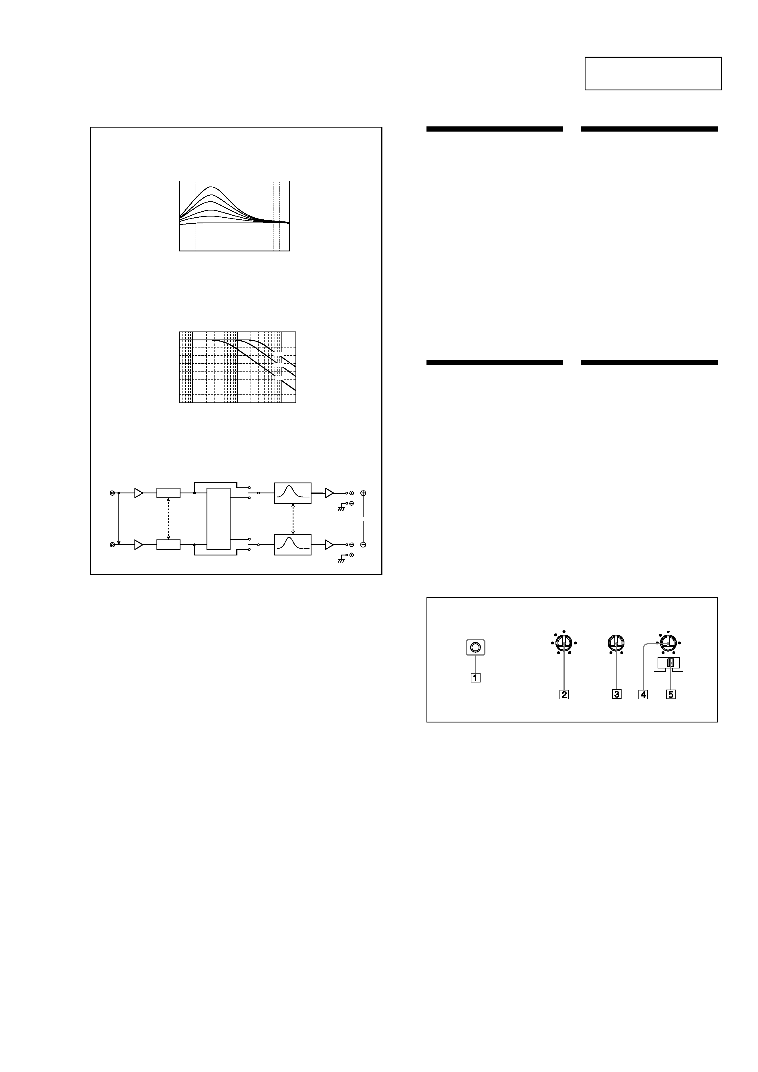
Circuit Diagram
Schéma du circuit
Low boost
Amplification de basses fréquences
Frequency/Fréquence
dB
Frequency/Fréquence
dB
Cut-off frequency (LPF)
Fréquence de coupure (LPF)
POWER/PROTECTOR
FILTER
OFF
LPF
LEVEL
LOW BOOST
(40Hz)
0
+10dB
6
0.3V
2
4
5.5
0.5
60
50
300Hz
170
110
260
10
10
0
40
100
1k
10
0
-10
-20
-30
-40
-50
-60
-70
-80
10
100
1k
50Hz
170Hz
300Hz
LEVEL
LPF
Normal
AMP
Power
Lch
LEVEL
Inverted
AMP
Power
Rch
BTL.
Lch
Rch
(BTL.)
LOW BOOST
LOW BOOST
Hz
Hz
Location and Function
of Controls
1
POWER/PROTECTOR indicator
Lights up in green during operation.
When the PROTECTOR is activated the
indicator will change from green to red.
When the PROTECTOR is activated refer to
the Troubleshooting Guide.
2
LEVEL adjustment control
The input level can be adjusted with this
control. Turn it in the clockwise direction
when the output level of the car audio
seemslow.
3
LOW BOOST level control
Turn this control to boost the frequencies
around 40 Hz to a maximum of 10 dB.
4
Cut-off frequency adjustment control
Setsthe cut-off frequency (50 300Hz) for
the low-pass filter.
5
FILTER selector switch
When the switch is in the LPF position, the
filter is set to low-pass.
Emplacement et fonction
des commandes
1
Indicateur POWER/PROTECTOR
S'allume en vert en cours de fonctionnement.
Lorsque PROTECTOR est activé, le voyant
passedu vert au rouge.
Lorsque PROTECTOR est activé, reportez-
vous au guide de dépannage.
2
Commande de réglage LEVEL
Le niveau d' entrée peut se régler avec cette
commande. Tournez cette commande dans
le sens des aiguilles d'une montre lorsque le
niveau de sortie de l'autoradio semble faible.
3
Commande de niveau LOW BOOST
Tournez cette commande pour amplifier les
fréquencesautour de 40 Hz jusqu'à un
maximum de 10 dB.
4
Commandes de réglage de la fréquence
de coupure
Permet de régler la fréquence de coupure
(50 300Hz) pour le filtre passe-bas.
5
Commutateur de sélection FILTER
Lorsque le commutateur de sélection est en
position LPF, le filtre est réglé sur passe-bas.
4
XM-2200GTX
BTL
BTL
OFF
LPF
BTL
BTL
BTL
BTL
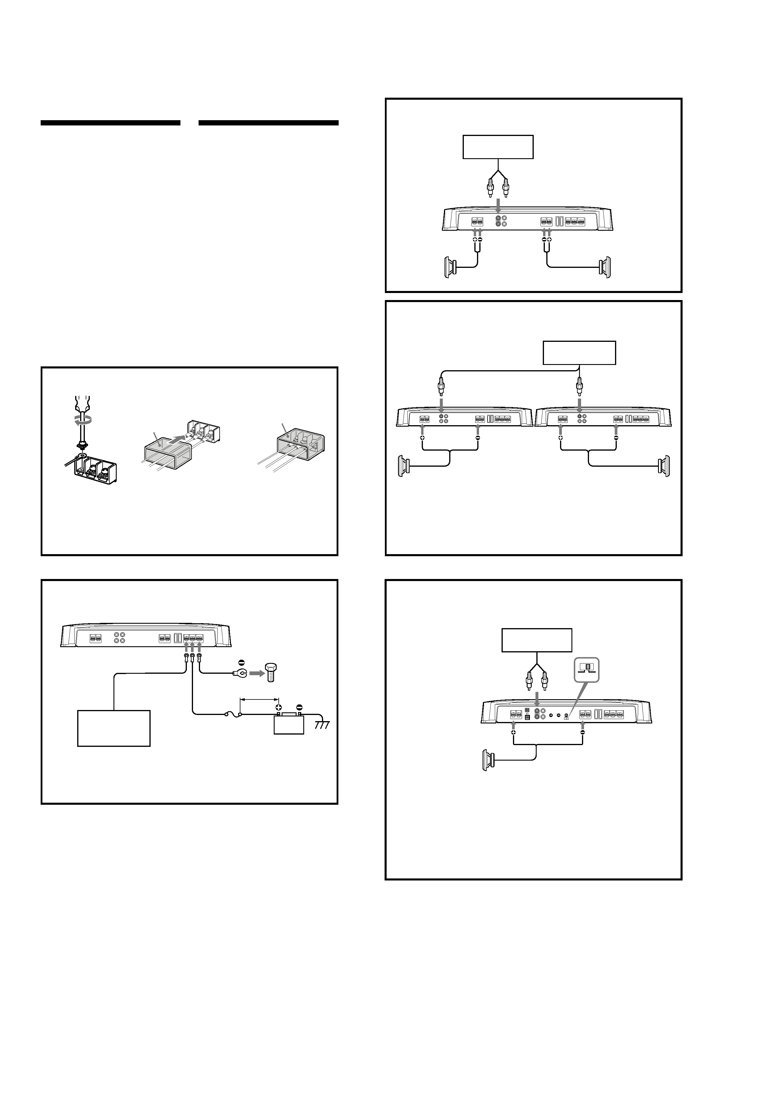
Connections
Caution
· Before making any connections, disconnect
the ground terminal of the car battery to avoid
short circuits.
· Besure to use speakerswith an adequate
power rating. If you use small capacity
speakers,they may be damaged.
· Do not connect the # terminal of the speaker
system to the car chassis, and do not connect
the # terminal of the right speaker with that
of the left speaker.
· Install the input and output cords away from
the power supply wire as running them close
together can generate some interference noise.
· This unit is a high powered amplifier.
Therefore, it may not perform to its full
potential if used with the speaker cords
supplied with the car.
· If your car is equipped with a computer
system for navigation or some other purpose,
do not to remove the ground wire from the
car battery. If you disconnect the wire, the
computer memory may be erased.To avoid
short circuits when making connections,
disconnect the +12 V power supply wire until
all the other wires have been connected.
Connexions
2-Speaker System
Système à 2 haut-parleurs
Car audio
Autoradio
LINE OUT
Left speaker
(min. 2
)
Haut-parleur
gauche
(min. 2
)
Right speaker
(min. 2
)
Haut-parleur
droit
(min. 2
)
As a Monaural Amplifier
Comme amplificateur monaural
Car audio
Autoradio
LINE OUT
Right channel
Canal droit
Left channel
Canal gauche
Right speaker
(min. 4
)
Haut-parleur droit
(min. 4
)
Pour plus de détails sur les réglages des
commutateurs et commandes, reportez-vous à
« Emplacement et fonction des commandes ».
Remarque
Vérifiez que la sortie de ligne de l'autoradio est
raccordée à la prise portant l'indication
« L (BTL) » sur l'appareil.
Left speaker (min. 4
)
Haut-parleur gauche
(min. 4
)
As the Monaural Amplifier for a Subwoofer
Comme amplificateur monaural pour un haut-parleur
d'extrêmes graves
Car audio
Autoradio
LINE OUT
For details on the settings of switches and
controls, refer to "Location and Function of
Controls."
Note
Make sure that the line output from the car
audio is connected to the jack marked "L (BTL)"
on the unit.
For details on the settings of switches and
controls, refer to "Location and Function of
Controls."
Note
If you wish to use a subwoofer as a monaural
speaker, connect the speaker as illustrated
above. The output signals to the subwoofer
will be the combination of the both right and
left output signals.
Pour plus de détails sur les réglages des
commutateurs et commandes, reportez-vous à
« Emplacement et fonction des commandes ».
Remarque
Si vous désirez utiliser un haut-parleur
d'extrêmes graves comme haut-parleur
monaural, raccordez le haut-parleur comme
illustré ci-dessus.Les signaux de sortie vers le
haut-parleur d'extrêmes graves seront une
combinaison des signaux de sortie droit et
gauche.
Attention
· Avant d'effectuer les connexions, débranchez
la borne de massede la batterie de voiture
pour éviter tout court-circuit.
· Veillez à utiliser des haut-parleurs de
puissance adéquate. Si vous utilisez des haut-
parleurs de faible capacité,ils risquent d'être
endommagés.
· Ne raccordez pas la borne # du systèmede
haut-parleurs à la carrosseriede la voiture ni
la borne # du haut-parleur droit avec celle du
haut-parleur gauche.
· Eloignez les câblesd'entrée et de sortie du
câble d'alimentation pour éviter les
interférences.
· Cet appareil est un amplificateur de haute
puissance.Il ne peut donc déployer sa pleine
puissance que si les câblesde haut-parleurs de
la voiture lui sont raccordés.
· Si votre voiture est équipée d'un systèmede
navigation ou d'un ordinateur de bord, ne
retirez pas le fil de terre de la batterie de la
voiture, sinon les données mémoriséesseront
effacées.Pour éviter un court-circuit lorsque
vous effectuez les branchements, branchez le
câble d'alimentation +12 V après avoir
branché tous les autres fils.
Power Connection Wires
Câbles d'alimentation
Car audio
Autoradio
Fuse (80 A)
Fusible (80 A)
+12 V car battery
Batterie de voiture +12 V
Remote output *1
Sortie de
télécommande *1
(REM OUT)
to a metal point
of the car
vers une partie
métallique de la
carrosserie
*
1
If you have the factory original or some other car audio without a remote output on the amplifier,
connect the remote input terminal (REMOTE) to the accessory power supply.
*
1
Si vous disposez du modèle d'origine ou d'un autre autoradio dont l'amplificateur ne comporte pas de
sortie de télécommande, raccordez la borne d'entrée de télécommande (REMOTE) à la prise
d'alimentation
accessoires.
Notes on the power supply
·
Connect the +12 V power supply wire only after
all the other wires have been connected.
·
Be sure to connect the ground wire of the unit
securelyto a metal point of the car. A loose
connection may causea malfunction of the
amplifier.
·
Be sure to connect the remote control wire of the
car audio to the remote terminal.
·When using a car audio without a remote output
on the amplifier, connect the remote input
terminal (REMOTE)to the accessorypower supply.
·
Use the power supply wire with a fuse attached
(80 A).
·
All power wires connected to the positive battery
post should be fused within 456 mm (18 in) of the
battery post, and before they pass through any
metal.
·
Make sure that the vehicle's battery wires
connected to the vehicle (ground to chassis)*2 are
of a wire gauge at least equal to that of the main
power wire connected from the battery to the
amplifier.
·
Make sure that the wires to be connected to the
+12 V and GND terminals of this unit are at least
4-Gauge (AWG-4) or have a sectional area of
more than 22.0 mm 2 (7/8 in. 2).
Remarquessur l'alimentation électrique
·
Raccordez le câble d'alimentation
+12 V
uniquement après avoir réalisé toutes les autres
connexions.
·
Raccordezcorrectement le fil de masseà une
partie métallique de la voiture. Une connexion
lâche peut provoquer un dysfonctionnement de
l'amplificateur.
·
Veillez à raccorder le fil de télécommande de
l'autoradio à la borne de télécommande.
·
Si vous utilisez un autoradio dont l'amplificateur
ne comporte pas de sortie de télécommande,
raccordez la borne d'entrée de la télécommande
(REMOTE)à la prise d'alimentation
accessoires.
·
Utilisez un câble d'alimentation
muni d'un fusible
(80 A).
·
Tous les fils électriques raccordés au support de
batterie positif doivent être protégés par un
fusible à une distance maximum de 456 mm (18
po) du support de batterie et avant de passer
dans une partie métallique quelconque.
·
Assurez-vous que les fils de la batterie du véhicule
raccordés à ce dernier (sol au châssis)*2 sont d'un
calibre au moins égal à celui du fil électrique
principal reliant la batterie et l'amplificateur.
·
Assurez-vous que les câbles à raccorder aux
bornes +12V et GND de cet appareil sont d'un
calibre d'au moins 4 (AWG-4) ou d'une section
supérieure à 22,0 mm 2 (7/8 po 2).
Pour plus de détails sur les réglages des
commutateurs et commandes, reportez-
vous à « Emplacement et fonction des
commandes ».
For details on the settings of switches and
controls, refer to "Location and Function of
Controls."
Subwoofer (min. 4
)
Haut-parleur d'extrêmes
graves (min. 4
)
Make the terminal connections as illustrated below.
Procédez aux connexions des bornes comme illustré ci-dessous.
REM +
12V
GND
REM
+12V
GND
Pass the wires through the cap, connect
the wires, then cover the terminals with
the cap.
Note
When you tighten the screw, be careful not to
apply too much torque * as doing so may damage
the screw.
* The torque value should be less than 1 N·m.
Faites passer les fils par le cache, raccordez
les fils, puis recouvrez les bornes avec le
cache.
Remarque
Lorsque vous vissez la vis, faites attention à ne
pas appliquer une trop grande force *, car cela
pourrait endommager la vis.
* Le couple de torsion doit être inférieur à 1 N·m.
3
3
c
less than 456 mm (18 in)
moins de 456 mm (18 po)
*2
5
XM-2200GTX
BTL
BTL
OFF
LPF
OFF
LPF
OFF
LPF
OFF
LPF
OFF
LPF
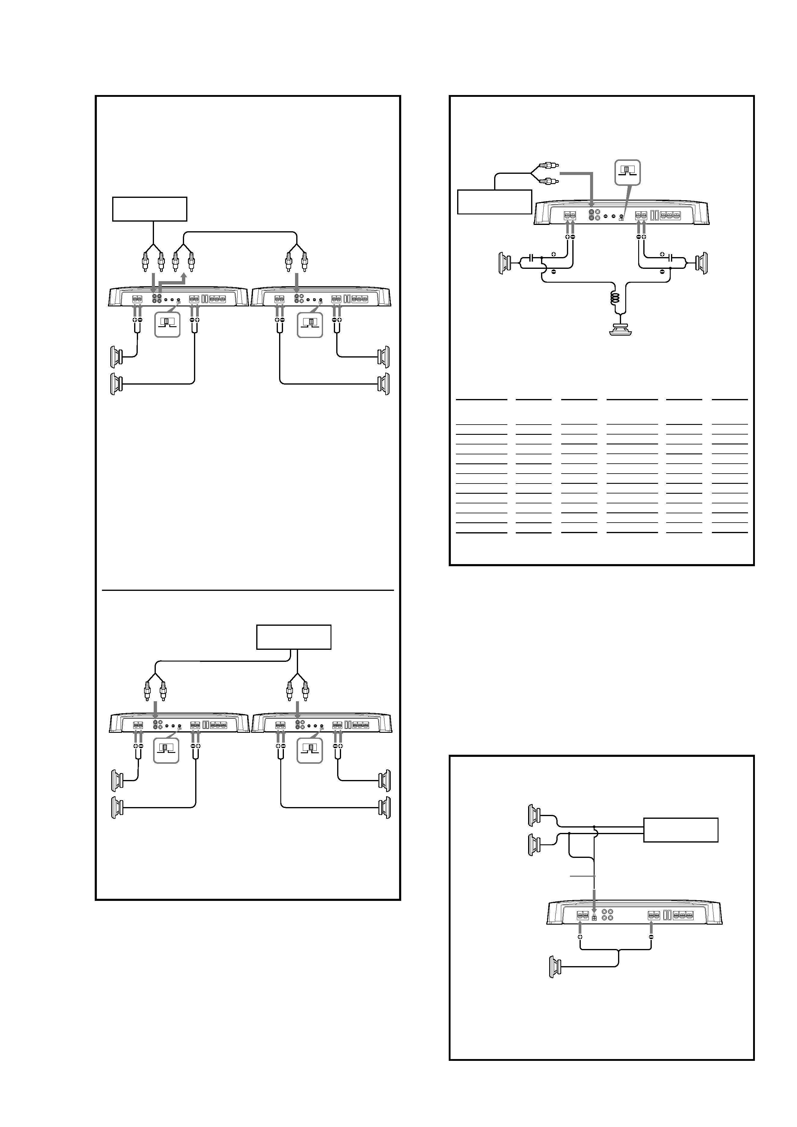
Four output channels
Quatre canaux de sortie
Full range speakers
(min. 2
)
Haut-parleurs à large
bande (min. 2
)
Subwoofers (min. 2
)
Haut-parleur d'extrêmes
graves (min. 2
)
Pour plus de détails sur les réglages des
commutateurs et commandes, reportez-vous à
« Emplacement et fonction des commandes ».
Remarque
Dans ce système, le volume des haut-parleurs
d'extrêmes graves est contrôlé par la
commande de balance avant/arrière de
l'autoradio.
For details on the settings of switches and
controls, refer to "Location and Function of
Controls."
Note
In this system, the volume of the subwoofers
will be controlled by the car audio fader
control.
Car audio
Autoradio
LINE OUT
Dual Mode System (With a Bridged Subwoofer)
Double mode de connexion (avec un haut-parleur
d'extrêmes graves en pont)
Notes
·When using passive crossover networks in a multi-
speaker system, care must be taken as the speaker
system's impedance should not be lower than that
of the suitable impedance for this unit.
·When you are installing a 12 decibels/octave system
in your car, the following points must be
considered. In a 12 decibels/octave system where
both a choke and capacitor are used in series to
form a circuit, a great care must be taken when
they are connected. In such a circuit, there is going
to be an increase in the current which by-passesthe
speaker with frequencies at around the crossover
frequency. If audio signals are continued to be fed
into the crossover frequency area, it may cause the
amplifier to become abnormally hot or the fuse will
be blown. Also if the speaker is disconnected, a
series-resonant circuit will be formed by the choke
and the capacitor. In this case, the impedance in the
resonance area will decrease dramatically resulting
in a short circuit like situation causing a damage to
the amplifier. Therefore, make sure that a speaker
is connected to such a circuit at all times.
Remarques
· Lorsque vous utilisez des circuits de recoupement de
fréquence passifs dans un système à plusieurs haut-parleurs,
assurez-vous que l'impédance du système n'est pas inférieure
à celle prévue pour cet appareil.
· Lorsque vous installez un système à 12 décibels/octave dans
votre voiture, vous devez respecter les points suivants. Dans
un système à 12 décibels/octave où la bobine d'arrêt et le
condensateur sont utilisés en série pour former un circuit,
vous devez réaliser les branchements avec beaucoup de
précaution. Dans ce type de circuit, une augmentation du
courant contournant le haut-parleur se produit dans les
fréquences se situant autour de la fréquence de coupure. Si
des signaux audio continuent d'être fournis dans la zone de
la fréquence de recoupement, une surchauffe risque de se
produire dans l'amplificateur et le fusible risque de griller. Si
le haut-parleur n'est pas raccordé, un circuit de résonance
série sera créé par la bobine et le condensateur. Dans ce cas,
l'impédance dans la zone de résonance sera
considérablement réduite, et comme dans le casd'un court-
circuit, l'amplificateur peut être endommagé. Par
conséquent, veillez à ce qu'un haut-parleur soit toujours
raccordé au circuit.
C1/C2
(capacitor)*
unit:
µF
800
500
400
300
270
200
150
100
68
50
39
Table of crossover values for
6 dB/octave (4
)
* (not supplied)
Crossover
Frequency
unit: Hz
50
80
100
130
150
200
260
400
600
800
1000
L
(coil)*
unit: mH
12.7
8.2
6.2
4.7
4.2
3.3
2.4
1.6
1.0
0.8
0.6
Fréquencede
recoupement
unité : Hz
50
80
100
130
150
200
260
400
600
800
1000
L
(bobine)*
unité : mH
12,7
8,2
6,2
4,7
4,2
3,3
2,4
1,6
1,0
0,8
0,6
C1/C2
(condensateur)*
unité :
µF
800
500
400
300
270
200
150
100
68
50
39
Tableau des valeurs de recoupement
pour 6 dB/octave (4
)
* (non fournis)
2-way System
Système 2 voies
Two output channels
Deux canaux de sortie
Full range speakers
(min. 2
)
Haut-parleurs à large
bande (min. 2
)
Subwoofers (min. 2
)
Haut-parleur d'extrêmes
graves (min. 2
)
Utilisez la borne THROUGH OUT lorsque
vous installez plusieurs amplificateurs. Les
signaux sont sortis comme ils sont entrés.
(LOW BOOST, LPF ne fonctionnent pas.)
Remarques
·Vous pouvez raccorder un maximum de 3
amplificateurs à la borne THROUGHOUT. Si
vous raccordez plus de trois amplificateurs,
cela peut provoquer des problèmes comme
des baissesdu son.
·Avec une connexion d'entrée de haut niveau,
vous ne pouvez pas utiliser THROUGHOUT.
Use the THROUGH OUT terminal when
you install more amplifiers. The signals are
output as they were input. (LOW BOOST,
LPF do not work.)
Notes
·A maximum 3 amplifiers can be connected to
the THROUGHOUT terminal. If you connect
more than three amplifiers, it may cause
problems such as sound dropout.
·High level input connection cannot use
THROUGHOUT.
Car audio
Autoradio
LINE OUT
THROUGH OUT
INPUT
INPUT
Car audio
Autoradio
Left speaker
Haut-parleur gauche
Right speaker
Haut-parleur droit
Subwoofer
Haut-parleur d'extrêmes graves
LINE OUT
C2
C1
L
High Level Input Connection (As a Monaural Amplifier for a Subwoofer)
Connexion d'entrée à haut niveau
(Comme amplificateur monaural pour un haut-parleur d'extrêmes graves)
Pour plus de détails sur les réglages des
commutateurs et commandes, reportez-vous à
« Emplacement et fonction des commandes ».
Remarque
Si vous désirez utiliser un haut-parleur d'extrêmes
graves comme haut-parleur monaural, raccordez
le haut-parleur comme illustré ci-dessus.Les
signaux de sortie vers le haut-parleur d'extrêmes
graves seront une combinaison des signaux de
sortie droit et gauche.
For details on the settings of switches and
controls, refer to "Location and Function of
Controls."
Note
If you wish to use a subwoofer as a monaural
speaker, connect the speaker as illustrated
above. The output signals to the subwoofer
will be the combination of both the right and
left output signals.
Car audio
Autoradio
Left speaker
Haut-parleur gauche
Right speaker
Haut-parleur droit
Subwoofer (min. 4
)
Haut-parleur d'extrêmes
graves (min. 4
)
2
*