MICROFILM
SERVICE MANUAL
STEREO POWER AMPLIFIER
US Model
Canadian Model
AEP Model
UK Model
SPECIFICATIONS
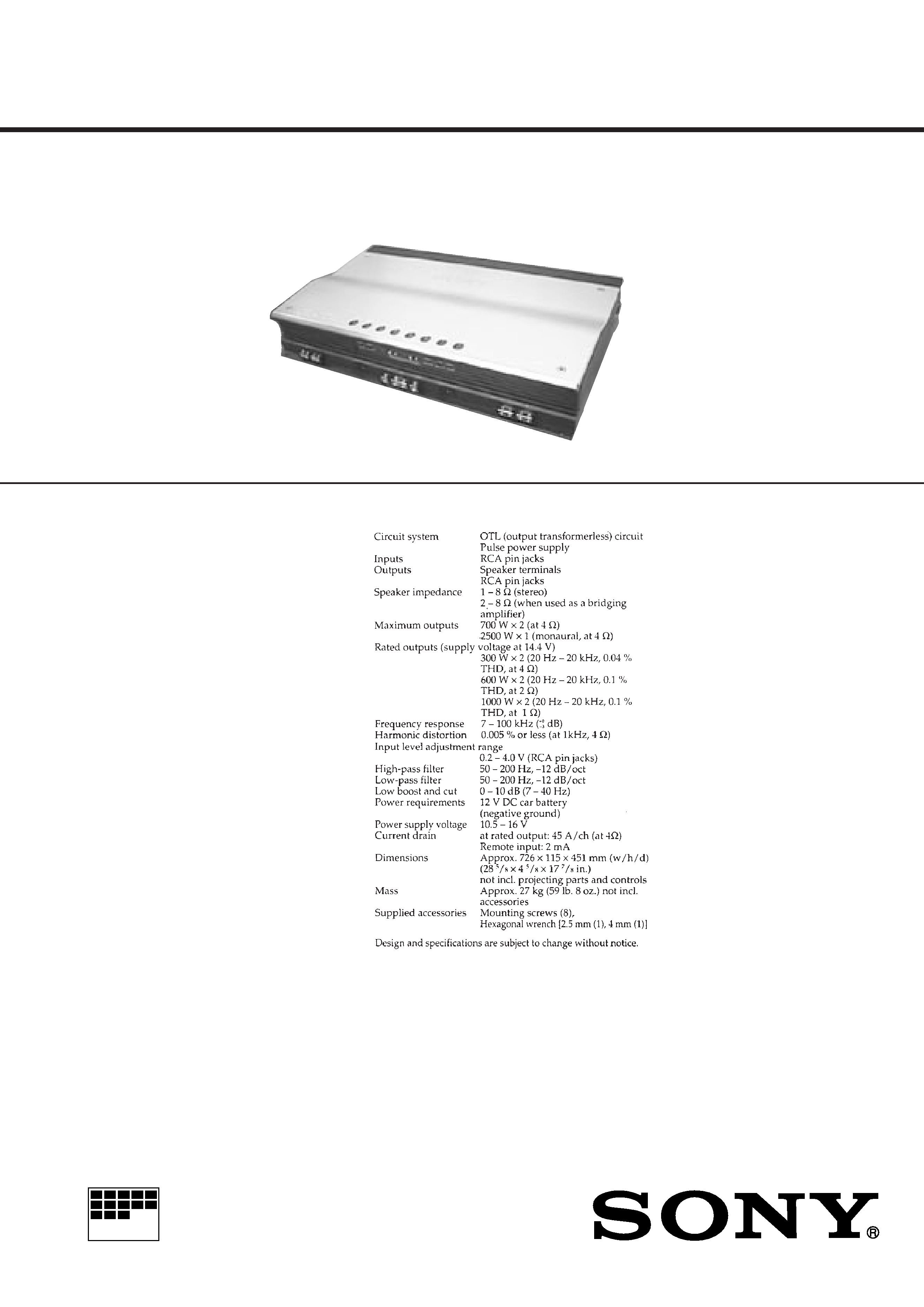
XM-2000R
Photo: AEP model

2
TABLE OF CONTENTS
1.
SERVICING NOTES ................................................ 3
2.
GENERAL ................................................................... 4
3.
DISASSEMBLY ......................................................... 8
4.
ELECTRICAL ADJUSTMENTS ......................... 9
5.
DIAGRAMS
5-1. Note for Printed Wiring Boards and
Schematic Diagrams ....................................................... 12
5-2. Printed Wiring Board PRE AMP Section ................ 13
5-3. Schematic Diagram PRE AMP Section .................... 15
5-4. Printed Wiring Boards PROTECT Section ............. 17
5-5. Schematic Diagram PROTECT Section .................. 19
5-6. Printed Wiring Boards
POWER AMP Section (Component Side) .............. 21
5-7. Printed Wiring Boards
POWER AMP Section (Conductor Side) ................ 23
5-8. Schematic Diagram POWER AMP Section ............ 25
6.
EXPLODED VIEWS ................................................ 28
7.
ELECTRICAL PARTS LIST ............................... 32
Notes on chip component replacement
· Never reuse a disconnected chip component.
· Notice that the minus side of a tantalum capacitor may be dam-
aged by heat.
3
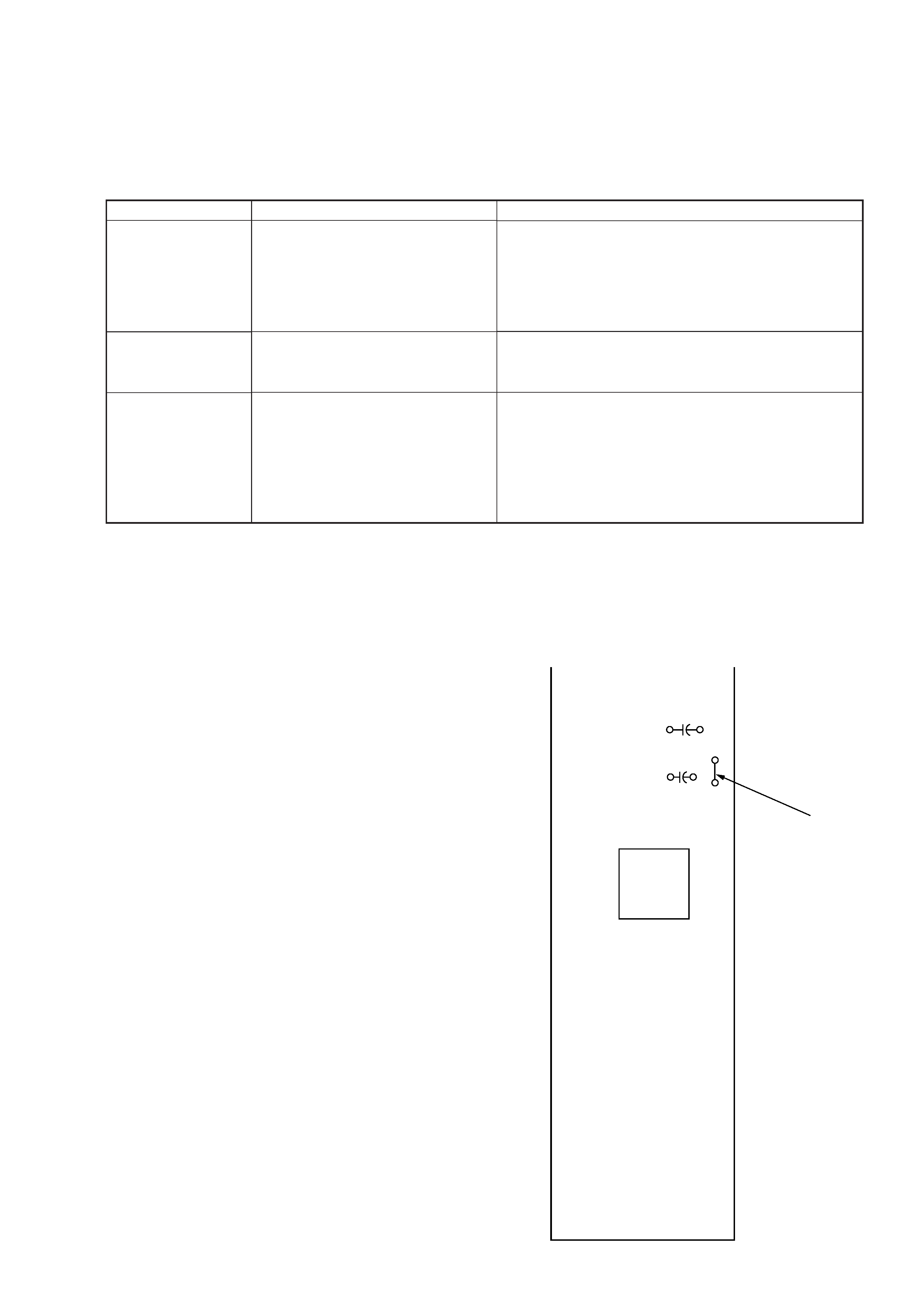
PROTECTOR
This set has protection circuit and indicators. When trouble oc-
curs, LED indicates status.
Each LED lights up in green during normal operation. The color
will change green to flashing red when trouble occurred.
SECTION 1
SERVICING NOTES
LED
OFFSET (D851)
OVER CURRENT *1
(D852)
THERMAL (D855)
Problem
· DC voltages are applied to the
SPEAKER OUT terminal (CN812,
CN813)
· DC voltages out to the SPEAKER
OUT terminal cause the internal cir-
cuit troubled
· The SPEAKER OUT terminal is
shorted
· The internal output element is troubled
· The temperature rises to unsafe level
Solution
Turn off the power switch. Make sure the speaker cord and
ground lead are securely connect
Turn off the power switch. Make sure the SPEAKER OUT
terminal are not short-circuited
The set heats up abnormally
· Stereo operation: 1 to 8
· Bridging operation: 2 to 8
Make sure to place the set in a ventilated location
(The color will return to green when the temperature returns
to normal)
*1: Does not work in no-signal condition.
TEST TONE
To check the system's status, activate the built in transmitter then
press the [TEST TONE] button (S801). If the tone is heard, the set
is functioning normally.
CANCELLING THE PROTECTOR AT THE SERVICE
Note: When check the protector, do not cancel it.
In case of a failure in this set, the protection circuit functions to
prevent a speaker damage and turn off the power to stop the set
working.
To make the set work at the service, disconnect the JW81 of the
PROTECT board and turn on the power.
Be sure to reconnect the JW81, after the completion of service.
+
+
C867
C871
T851
JW81
PROTECT OFF
(disconnect)
PROTECT Board
(Component Side)
4
SECTION 2
GENERAL
This section is extracted from
instruction manual.
5