
1
SERVICE MANUAL
US Model
E Model
XM-1652Z
STEREO POWER AMPLIFIER
AUDIO POWER SPECIFICATIONS (US model)
POWER OUTPUT AND TOTAL HARMONIC DISTORTION
165 watts per channel minimum continuous average power into 4 ohms,
both channels driven from 20 Hz to 20 kHz with no more than 0.04% total
harmonic distortion per Car Audio Ad Hoc Committee standards.
Other Specifications
Circuit system
OTL (output transformerless) circuit
Pulse power supply
Inputs
RCA pin jacks
High level input connector
Input level adjustment range
0.3 6 V (RCA pin jacks),
1.2 12 V (High level input)
Outputs
Speaker terminals
Speaker impedance
2 8
(stereo)
4 8
(when used as a bridging amplifier)
Maximum outputs
380 W
× 2 (at 4 )
1,000 W (BTL, at 4
)
Rated outputs (supply voltage at 14.4 V)
165 W RMS
× 2 (20 Hz 20 kHz, 0.04% THD+N, at 4 )
200 W RMS
× 2 (20 Hz 20 kHz, 0.1% THD+N, at 2 )
400 W RMS (BTL) (20 Hz 20 kHz, 0.1% THD+N,
at 4
)
S/N Ratio
93 dBA (reference: 1 W into 4
)
Frequency response
5 Hz 80 kHz (
dB)
Harmonic distortion
0.008% or less (at 1 kHz, 4
, 10 W)
Low-pass filter
80 Hz, 18 dB/oct
Power requirements
12 V DC car battery
(negative ground)
Power supply voltage
10.5 16 V
Current drain
at rated output : 40 A (4
, 165 W × 2)
Remote input : 1 mA
Dimensions
Approx. 424
× 55 × 290 mm
(16 3/4
× 2 1/4 × 11 1/2 in.) (w/h/d) not incl.
projecting parts and controls
Mass
Approx. 4.0 kg (8 lb. 13 oz.) not incl. accessories
Supplied accessories
Mounting screws (4)
High level input cord (1)
Protection cap (1)
Design and specifications are subject to change without
notice.
SPECIFICATIONS
+0
3
Ver. 1.0 2005. 01
9-879-394-01
2005A04-1
© 2005. 01
Sony Corporation
e Vehicle Company
Published by Sony Engineering Corporation

2
TABLE OF CONTENTS
1. GENERAL
Connections ............................................................................. 3
2. DISASSEMBLY
2-1. Bottom Plate ........................................................................ 5
2-2. Main Board Section ............................................................ 6
2-3. Main Board ......................................................................... 6
3. DIAGRAMS
3-1. Printed Wiring Board .......................................................... 9
3-2. Schematic Diagram ........................................................... 10
4. EXPLODED VIEWS
4-1. Heat Sink (Main) Section .................................................. 11
4-2. Main Board Section .......................................................... 12
5. ELECTRICAL PARTS LIST ........................................ 13
Notes on Chip Component Replacement
·Never reuse a disconnected chip component.
· Notice that the minus side of a tantalum capacitor may be dam-
aged by heat.
XM-1652Z
PROTECTOR OPERATION CHECK
Thermal Protect
1. Short across TH901 with the power on.
2. Verify that the protector is operated and LED901 illuminates
red.
3. Verify that the protector is released and LED901 illuminates green
when the short is removed.
4. Likewise, perform items 1 to 3 for TH902 and TH903.
Over Current Protect
1. Short between the positive and negative sides of the speaker
output terminal CN903 (1/2) with the power on.
(Perform this shorting for each channel on L and R.)
2. Verify that the protector is operated and LED901 illuminates
red.
3. Verify that the protector is not released and LED901 remains
red even when the short is removed.
4. Verify that the protector is released and LED901 illuminates green
when the power is turned off and then on again.
Offset Protect
1. Short between the +12V terminal of CN903 (2/2) and the BTL+
or BTL of the speaker output terminal CN903 (1/2).
(Short between +12V terminal and BTL+ and between +12V
terminal and BTL.)
2. Verify that the protector is operated and LED901 illuminates
red.
3. Verify that the protector is not released and LED901 remains
red even when the short is removed.
4. Verify that the protector is released and LED901 illuminates green
when the power is turned off and then on again.
SAFETY-RELATED COMPONENT WARNING!!
COMPONENTS IDENTIFIED BY MARK 0 OR DOTTED LINE
WITH MARK 0 ON THE SCHEMATIC DIAGRAMS AND IN
THE PARTS LIST ARE CRITICAL TO SAFE OPERATION.
REPLACE THESE COMPONENTS WITH SONY PARTS WHOSE
PART NUMBERS APPEAR AS SHOWN IN THIS MANUAL OR
IN SUPPLEMENTS PUBLISHED BY SONY.
3
XM-1652Z
SECTION 1
GENERAL
This section is extracted
from instruction manual.
Connections
Precautions
· This unit is designed for negative ground 12 V DC operation only.
· Use speakers with suitable impedance.
--2 8
(stereo), 4 8 (when used as a bridging amplifier).
· Do not connect any active speakers (with built-in amplifiers) to the speaker terminals of the unit. Doing
so may damage the amplifier and active speakers.
· Avoid installing the unit in areas subject to:
-- high temperatures such as from direct sunlight or hot air from the heater
-- rain or moisture
-- dust or dirt.
· If your car is parked in direct sunlight and there is a considerable rise in temperature inside the car,
allow the unit to cool down before use.
· When installing the unit horizontally, be sure not to cover the fins with the floor carpet etc.
· If this unit is placed too close to the car radio unit or antenna, interference may occur. In this case,
relocate the amplifier away from the car radio unit or antenna.
· If no power is being supplied to the car radio unit, check the connections.
· This power amplifier employs a protection circuit to protect the transistors and speakers if the amplifier
malfunctions. Do not attempt to test the protection circuits by covering the heat sink or connecting
improper loads.
· Do not use the unit on a weak battery as its optimum performance depends on a good power supply.
· For safety reasons, keep your car audio unit volume moderate so that you can still hear sounds outside
your car.
· By default, the FILTER selector switch is in "LPF" position. When connecting the full range speaker, set
to the "OFF" position.
Caution
· Before making any connections, disconnect the ground terminal of the car battery to avoid short circuits.
· Be sure to use speakers with an adequate power rating. If you use small capacity speakers, they may be
damaged.
· Do not connect the # terminal of the speaker system to the car chassis, and do not connect the #
terminal of the right speaker with that of the left speaker.
· Install the input and output cords away from the power supply wire as running them close together can
generate some interference noise.
· This unit is a high powered amplifier. Therefore, it may not perform to its full potential if used with the
speaker cords supplied with the car.
· If your car is equipped with a computer system for navigation or some other purpose, do not remove the
ground wire from the car battery. If you disconnect the wire, the computer memory may be erased. To
avoid short circuits when making connections, disconnect the +12 V power supply wire until all the
other wires have been connected.
Conexiones
Precauciones
· Esta unidad está diseñada para utilizarse sólo con cc de 12 V negativo a masa.
· Utilice altavoces con una impedancia adecuada.
-- de 2 a 8
(estéreo) , de 4 a 8 (cuando se utilizan como amplificadores en puente).
· No conecte altavoces activos (con amplificadores incorporados) a los terminales de altavoz de la unidad.
Si lo hace, puede dañar el amplificador y los altavoces activos.
· Evite instalar la unidad en lugares expuestos a:
-- altas temperaturas, como a la luz solar directa o al aire caliente de la calefacción
-- la lluvia o la humedad
-- suciedad o polvo.
· Si aparca el automóvil bajo la luz solar directa y se produce un considerable aumento de temperatura en
el interior, deje que la unidad se enfríe antes de utilizarla.
· Si instala la unidad horizontalmente, asegúrese de no cubrir las aletas con la moqueta del suelo, etc.
· Si conecta la unidad demasiado cerca de la radio o antena del automóvil, pueden producirse
interferencias. En este caso, aleje el amplificador de dicha radio o antena.
· Si la radio del automóvil no recibe alimentación, compruebe las conexiones.
· Este amplificador de potencia emplea un circuito de protección para proteger los transistores y los
altavoces en caso de que dicho amplificador presente fallas de funcionamiento. No intente someter a
prueba los circuitos de protección cubriendo el disipador de calor o conectando cargas inadecuadas.
· No utilice la unidad si la batería se está agotando, ya que el rendimiento óptimo de dicha unidad
depende de un buen suministro de alimentación.
· Por razones de seguridad, mantenga el volumen del sistema de audio para automóvil moderado de
forma que sea posible oír los sonidos del exterior del automóvil.
· Por defecto, el interruptor de selección FILTER se encuentra en la posición "LPF". Al conectar el altavoz
de rango completo, ajuste el interruptor en la posición "OFF".
Precaución
· Antes de realizar las conexiones, desconecte el terminal de toma a tierra de la batería del automóvil para
evitar cortocircuitos.
· Asegúrese de utilizar altavoces con una potencia nominal adecuada. Si emplea altavoces de pequeña
capacidad, pueden dañarse.
· No conecte el terminal # del sistema de altavoces al chasis del automóvil, ni el terminal # del altavoz
derecho al del altavoz izquierdo.
· Instale los cables de entrada y salida alejados del cable de suministro de alimentación, ya que en caso
contrario puede generarse ruido por interferencias.
· Esta unidad es un amplificador de alta potencia. Por tanto, puede no funcionar a pleno rendimiento si se
utiliza con los cables de altavoz suministrados con el automóvil.
· Si el automóvil está equipado con un sistema de computadora para la navegación o para otra finalidad,
no desconecte el conductor de toma a tierra de la batería del automóvil. Si lo desconecta, la memoria de
la computadora puede borrarse. Para evitar cortocircuitos al realizar las conexiones, desconecte el cable
de suministro de alimentación de +12 V hasta conectar todos los cables.
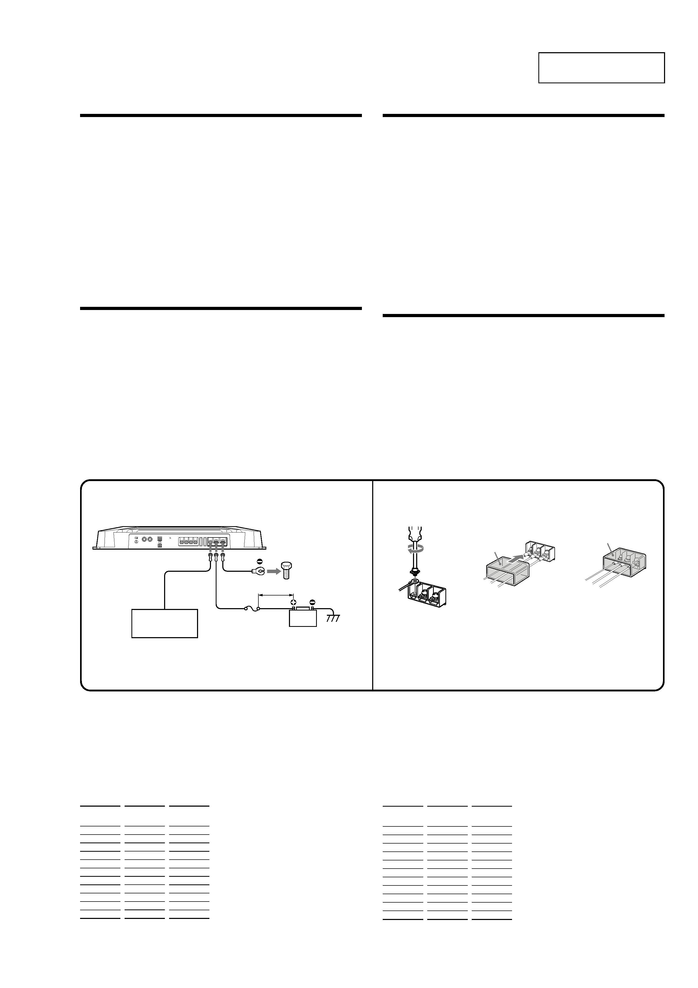
Power Connection Wires (not supplied)
Cables de conexión de alimentación (no suministrados)
Fuse (60 A)
Fusible (60 A)
+12 V car battery
Batería de automóvil de +12 V
Car audio unit
Sistema de audio para
automóvil
to a metal point of the car
a un punto metálico del
automóvil
REM
+12V
GND
REM +
12V
GN
D
3
3
Notes on the power supply
· Connect the +12 V power supply wire only after all the other wires have been connected.
· Be sure to connect the ground wire of the unit securely to a metal point of the car. A loose connection may
cause a malfunction of the amplifier.
· Be sure to connect the remote control wire of the car audio unit to the remote terminal.
· When using a car audio unit without a remote output on the amplifier, connect the remote input terminal
(REMOTE) to the accessory power supply.
· Use the power supply wire with a fuse attached (60 A).
· All power wires connected to the positive battery post should be fused within 450 mm (18 in) of the battery post,
and before they pass through any metal.
· Make sure that the vehicle's battery wires connected to the vehicle (ground to chassis) *2 are of a wire gauge at
least equal to that of the main power wire connected from the battery to the amplifier.
· Make sure that the wires to be connected to the +12 V and GND terminals of this unit at least 8-Gauge (AWG-8)
or have a sectional area of more than 8 mm 2(11/32 in 2).
Notas sobre el suministro de alimentación
· Conecte el cable de suministro de alimentación de +12 V sólo después de haber conectado los otros cables.
· Asegúrese de conectar firmemente el cable de toma a tierra de la unidad a un punto metálico del automóvil.
Una conexión floja puede causar fallas de funcionamiento del amplificador.
· Compruebe que conecta el cable de control remoto del sistema de audio para automóvil al terminal remoto.
· Si utiliza un sistema de audio para automóvil sin salida remota en el amplificador, conecte el terminal de entrada
remota (REMOTE) al suministro de alimentación accesoria.
· Emplee el cable de suministro de alimentación con un fusible fijado (60 A).
· Todos los cables de alimentación conectados al polo positivo de la batería deben conectarse a un fusible situado a
menos de 450 mm del polo de la batería, y antes de pasar por ninguna pieza metálica.
· Asegúrese de que los cables de la batería del vehículo conectados al mismo (a la masa del chasis) *2 tiene una
anchura igual o superior a la del cable de alimentación principal que conecta la batería con el amplificador.
· Compruebe que los cables que se van a conectar a los terminales +12 V y GND de esta unidad tengan una
capacidad de al menos 8-Gauge (AWG 8) o una zona de sección de más de 8 mm 2.
Remote output *1
Salida remota *1
(REM)
*1 If you have the factory original or some other car
audio unit without a remote output for the amplifier,
connect the remote input terminal (REMOTE) to the
accessory power supply.
Make the terminal connections as illustrated below.
Realice las conexiones de terminal como se ilustra a continuación.
Pase los cables a través de la cubierta,
conéctelos y cubra los terminales con dicha
cubierta.
Nota
Al apretar el tornillo, tenga cuidado de no aplicar
demasiada fuerza de torsión *, ya que puede
dañarlo.
* El valor de fuerza de torsión debe ser inferior a
1 N·m.
Pass the wires through the cap, connect the
wires, then cover the terminals with the cap.
Note
When you tighten the screw, be careful not to
apply too much torque * as doing so may damage
the screw.
* The torque value should be less than 1 N·m.
c
*1 Si dispone del sistema de audio para automóvil
original de fábrica o de otro sistema sin una salida
remota en el amplificador, conecte el terminal de
entrada remota (REMOTE) al suministro de
alimentación accesoria.
Notes
· When using passive crossover networks in a multi-
speaker system, care must be taken as the speaker
system's impedance should not be lower than that of the
suitable impedance for this unit.
· When you are installing a 12 decibels/octave system in
your car, the following points must be considered. In a
12 decibels/octave system where both a choke and
capacitor are used in series to form a circuit, great care
must be taken when they are connected. In such a
circuit, there is going to be an increase in the current
which bypasses the speaker with frequencies around the
crossover frequency. If audio signals continue to be fed
into the crossover frequency area, it may cause the
amplifier to become abnormally hot or the fuse to blow.
Also if the speaker is disconnected, a series-resonant
circuit will be formed by the choke and the capacitor. In
this case, the impedance in the resonance area will
decrease dramatically resulting in a short circuit situation
causing damage to the amplifier. Therefore, make sure
that a speaker is connected to such a circuit at all times.
Notas
·A l utilizar redes de cruce pasivas en un sistema con
múltiples altavoces, es necesario asegurar que la
impedancia del sistema de altavoces no sea inferior al
valor de impedancia adecuado para esta unidad.
·A l instalar un sistema de 12 decibelios/octava en un
automóvil, hay que tener en cuenta los siguientes puntos.
En un sistema de 12 decibelios/octava donde se emplea
una bobina de choque y un condensador en serie para
formar un circuito, hay que tener mucho cuidado al
conectarlos. En los circuitos de este tipo, se produce un
aumento de la corriente que pasa por alto el altavoz, con
frecuencias próximas a la frecuencia de cruce. Si las
señales de audio siguen enviándose a la zona de
frecuencia de cruce, puede producirse un
sobrecalentamiento anormal del amplificador o puede
fundirse el fusible. Además, si se desconecta el altavoz, se
formará un circuito de resonancia en serie compuesto por
la bobina y el condensador. En este caso, la impedancia
del área de resonancia disminuirá considerablemente,
dando lugar a una situación de cortocircuito y dañando el
altavoz. Por tanto, es necesario asegurar que el altavoz
esté conectado a un circuito en todo momento.
Crossover
Frequency unit:
Hz
50
80
100
130
150
200
260
400
600
800
1000
L
(coil)* unit:
mH
12.7
8.2
6.2
4.7
4.2
3.3
2.4
1.6
1.0
0.8
0.6
C1/C2
(capacitor)* unit:
µF
800
500
400
300
270
200
150
100
68
50
39
Table of crossover values for 6 dB/octave (4 ohms) (Speaker Connections 4)
Frecuencia de
cruce
unidad: Hz
50
80
100
130
150
200
260
400
600
800
1000
L
(bobina) *
unidad: mH
12,7
8,2
6,2
4,7
4,2
3,3
2,4
1,6
1,0
0,8
0,6
C1/C2
(condensador) *
unidad:
µF
800
500
400
300
270
200
150
100
68
50
39
Tabla de valores de cruce para 6 dB/octava (4 ) (Conexiones de los altavoces 4)
* No suministrado
less than 450 mm (18 in)
menos de 450 mm
* Not supplied
*2
4
XM-1652Z
(80Hz)
OFF
ON
LPF
(80Hz)
OFF
ON
LPF
BTL
BTL
BTL
BTL
(80Hz)
OFF
ON
LPF
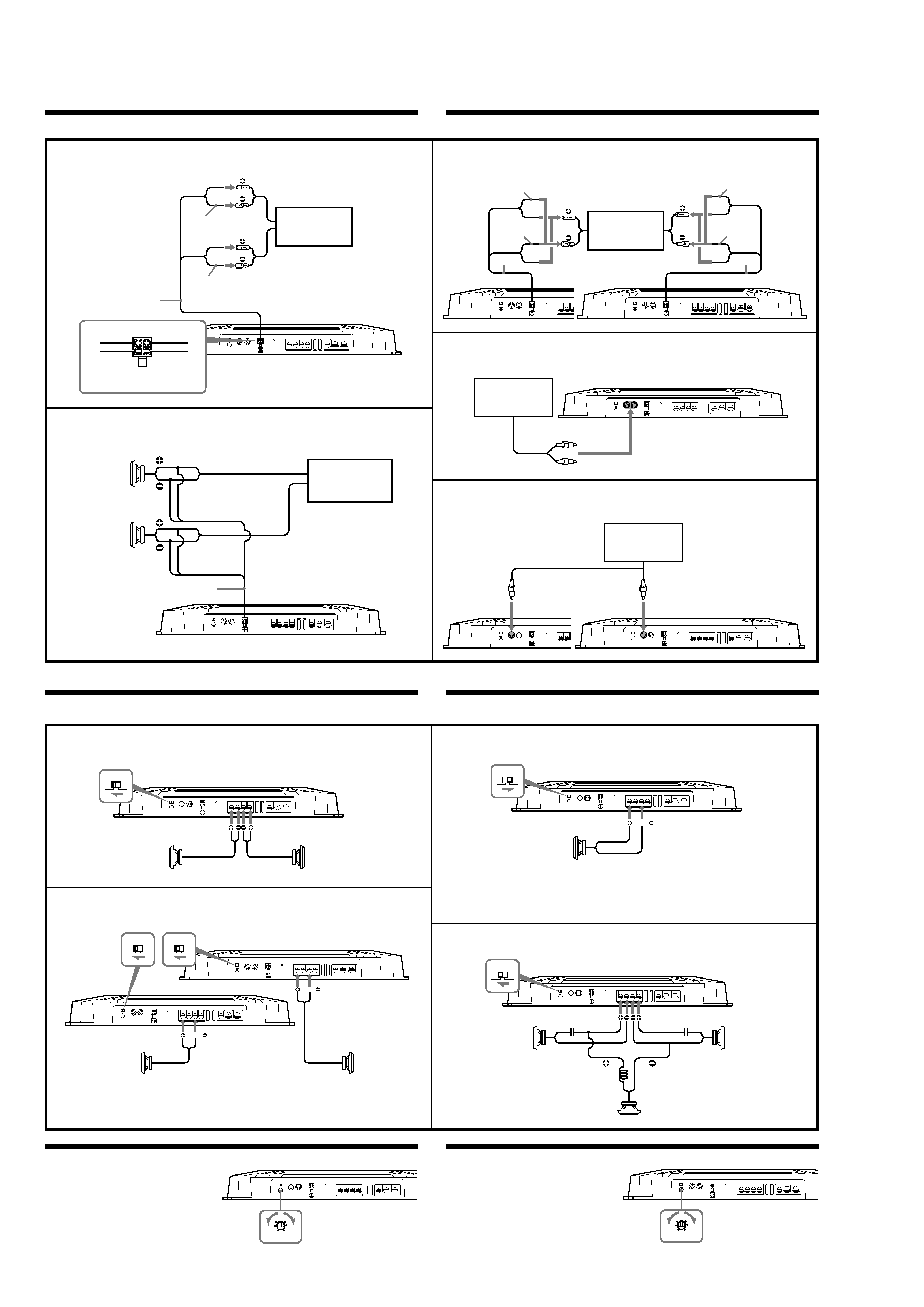
Input Connections
Speaker Connections
Turn on or off the LPF switch at the unit rear as illustrated below.
Conexiones de entrada
Conexiones de los altavoces
Encienda o apague el interruptor LPF situado en la parte posterior de la unidad, como se muestra a continuación.
High Level Input Connection (with Speaker Connection 1 or 4)
Conexión de entrada de alto nivel (con conexión de altavoces 1 ó 4)
A
A
A
A
A
High Level Input Connection (with Speaker Connection 3)
Conexión de entrada de alto nivel (con conexión de altavoces 3)
B
B
B
B
B
High Level Input Connection (with Speaker Connection 2)
Conexión de entrada de alto nivel (con conexión de altavoces2)
Line Input Connection (with Speaker Connection 1, 2 or 4)
Conexión de entrada de línea (con conexión de altavoces 1, 2 ó 4)
Line Input Connection (with Speaker Connection 3)
Conexión de entrada de línea (con conexión de altavoces 3)
C
C
C
C
C
D
D
D
D
D
E
E
E
E
E
(80Hz)
OFF
ON
LPF
Right speaker
Altavoz derecho
Left speaker
Altavoz izquierdo
White
Blanco
Gray
Gris
2
Striped
Con rayas
Striped
Con rayas
2-Speaker System (with Input Connection A or D)
Sistema de 2 altavoces (con conexión de entrada A o D)
1
1
1
1
1
Note
Make sure that the line output from the car audio unit is
connected to the jack marked "L (BTL)" on the unit.
Note
If you wish to use a subwoofer as the monaural speaker,
connect the speaker as illustrated above. The output
signals to the subwoofer will be the combination of
both right and left output signals.
Left speaker output
Salida del altavoz izquierdo
Right speaker output
Salida del altavoz derecho
Striped
Con rayas
Striped
Con rayas
Car audio unit
Sistema de audio para
automóvil
White
Blanco
Gray
Gris
White
Blanco
White/Black
striped
Con rayas
blancas y negras
Gray/Black
striped
Con rayas
grises y negras
Gray
Gris
2
R
L
Left speaker output
Salida del altavoz
izquierdo
Right speaker output
Salida del altavoz
derecho
Striped
Con rayas
Striped
Con rayas
Striped
Con rayas
Striped
Con rayas
Car audio unit
Sistema de audio para
automóvil
2
2
LINE OUT
Right channel
Canal derecho
Left channel
Canal izquierdo
LINE OUT
Left speaker (min. 2 )
Altavoz izquierdo (mín. 2 )
Right speaker (min. 2 )
Altavoz derecho (mín. 2 )
Subwoofer (with Input Connection C or D)
Altavoz potenciador de graves (con conexión de entrada C o D)
2
2
2
2
2
1-Speaker System (with Input Connection B or E)
Sistema de 1 altavoz (con conexión de entrada B o E)
3
3
3
3
3
C1
C2
L
Subwoofer
Altavoz potenciador de graves
Left speaker
Altavoz izquierdo
Right speaker
Altavoz derecho
Dual Mode System (with a Bridged Subwoofer A or D)
Sistema de modo dual (con altavoz potenciador de graves en puente A o D)
4
4
4
4
4
BTL
BTL
(80Hz)
OFF
ON
LPF
Subwoofer (min. 4 )
Altavoz potenciador de graves
(mín. 4 )
Right speaker
(min. 4 )
Altavoz derecho
(mín. 4 )
Left speaker
(min. 4 )
Altavoz izquierdo
(mín. 4 )
L (BTL)
L (BTL)
Nota
Si desea utilizar el altavoz potenciador de graves como
altavoz
monoaural, conecte el altavoz tal como se
muestra en la ilustración anterior. Las señales
que se
emiten hacia el altavoz potenciador de graves serán una
combinación de las señales de salida derecha e izquierda.
Nota
Asegúrese de que la salida de línea del sistema de audio
para automóvil está conectada a la toma con la marca
"L (BTL)" de la unidad.
Car audio unit
Sistema de audio para
automóvil
Car audio unit
Sistema de audio para
automóvil
Car audio unit
Sistema de audio para
automóvil
Level Adjustment Control
The input level can be adjusted with this control
when using source equipment made by other
manufacturers. Turn it in the clockwise direction
when the output level of the car audio unit
seems low.
Control de ajuste de nivel
Es posible ajustar el nivel de entrada con este
control al utilizar equipos fuente de otros
fabricantes. Gírelo en el sentido de las agujas del
reloj si el nivel de salida del sistema de audio
para automóvil parece bajo.
0.3V
6
4
2
1
0.5
LEVEL
0.3V
6
4
2
1
0.5
LEVEL
5
XM-1652Z
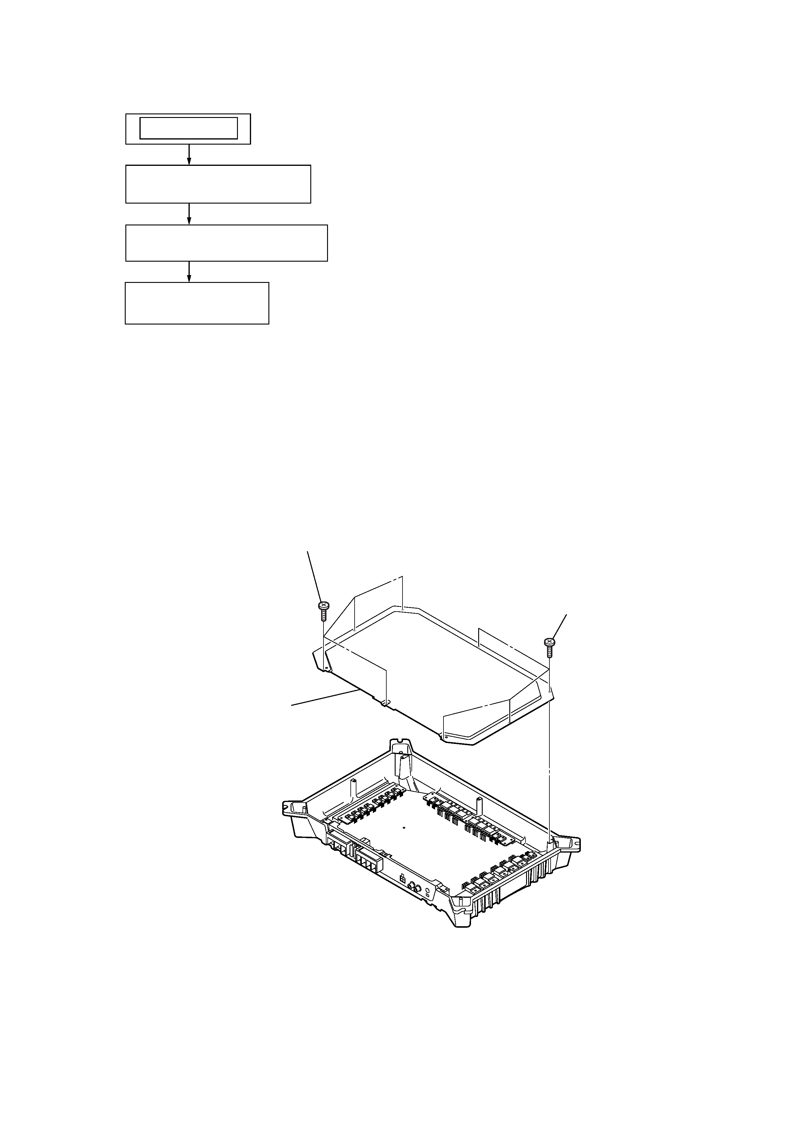
SECTION 2
DISASSEMBLY
Note : This set can be disassemble according to the following sequence.
Note : Follow the disassembly procedure in the numerical order given.
2-1. BOTTOM PLATE
2-1.
BOTTOM PLATE
(Page 5)
2-2.
MAIN BOARD SECTION
(Page 6)
SET
2-3.
MAIN BOARD
(Page 6)
3
bottom plate
1
four screws
(+BTP 3
x 5)
2
four screws
(+BTP 3
x 5)