
CCD B/W VIDEO
CAMERA MODULE
XC-ST70/70CE
User's
Guide
(Ver. 1.0) -- English --

XC-ST70/70CE
Table of Contents
OUTLINE ................................................................................................................. 1
MAIN FEATURES .................................................................................................... 1
SYSTEM CONFIGURATION ................................................................................... 2
MAIN SPECIFICATIONS ......................................................................................... 3
CONNECTION DIAGRAM ....................................................................................... 4
LOCATION OF PARTS AND OPERATION ............................................................. 5
PHASE CONDITIONS OF EXTERNAL SYNCHRONIZATION ................................ 6
ELECTRONIC SHUTTER ........................................................................................ 7
RESTART RESET (R.R) ........................................................................................ 10
FRAME IMAGE OUTPUT WITH STROBE LIGHT ................................................ 12
OUTPUT WAVEFORM TIMING CHART ............................................................... 13
TIMING CHART OF EXTERNAL TRIGGER SHUTTER - MODE 1 ....................... 17
TIMING CHART OF EXTERNAL TRIGGER SHUTTER - MODE 2 ....................... 23
DIMENSIONS ........................................................................................................ 25
SPECTRAL SENSITIVITY CHARACTERISTICS (TYPICAL VALUE) ................... 26
VARIOUS LENS SELECTION ............................................................................... 27

1
XC-ST70/70CE
OUTLINE
The XC-ST70/70CE is a compact, lightweight black-and-white camera module using the latest technology and a 2/3-
inch new-generation CCD. Each mode can be set by selecting the switches on the rear panel. The XC-ST70/70CE
provides an external trigger shutter that can catch a high-speed moving subject using an external signal. This enables
a still image to be read in arbitrary timing. The XC-ST70/70CE meets the high-level needs of image inspection based
on a high-definition image utilizing a 2/3-inch CCD that is popular in the image processing field.
In addition, the XC-ST70/70CE incorporates significant shock and vibration resistance allowing it to be easily
incorporated into machine vision equipment.
MAIN FEATURES
2/3" IT CCD
External trigger shutter function
(XC-ST70: 1/4 to 1/10,000 seconds, XC-ST70CE: 1/4 to 1/8,000 seconds)
Inputting the trigger pulse gives one still image. This feature allows the capture of high-speed moving object.
Restart Reset (R.R) function
Inputting HD and VD signals (2 VD or more) continuously from the outside can catch one image at arbitrary time
and control the stored CCD.
This function is used for long exposures and strobe with frame image output.
Synchronization system: Internal/external HD/VD, and VS
(VS is used only during external synchronization.)
Inputting an HD/VD signal from the outside automatically establishes external synchronization.
This function is effective for controlling multiple cameras efficiently from the external system.
All control switches on outside of camera.
Setting each mode on rear panel:
The setting of each mode can be changed by selecting DIP
Almost all switches are located on the rear panel. This feature permits easy setting after equipment is installed.
Compact and lightweight
C-mount
Excellent shock and vibration resistance
2
XC-ST70/70CE
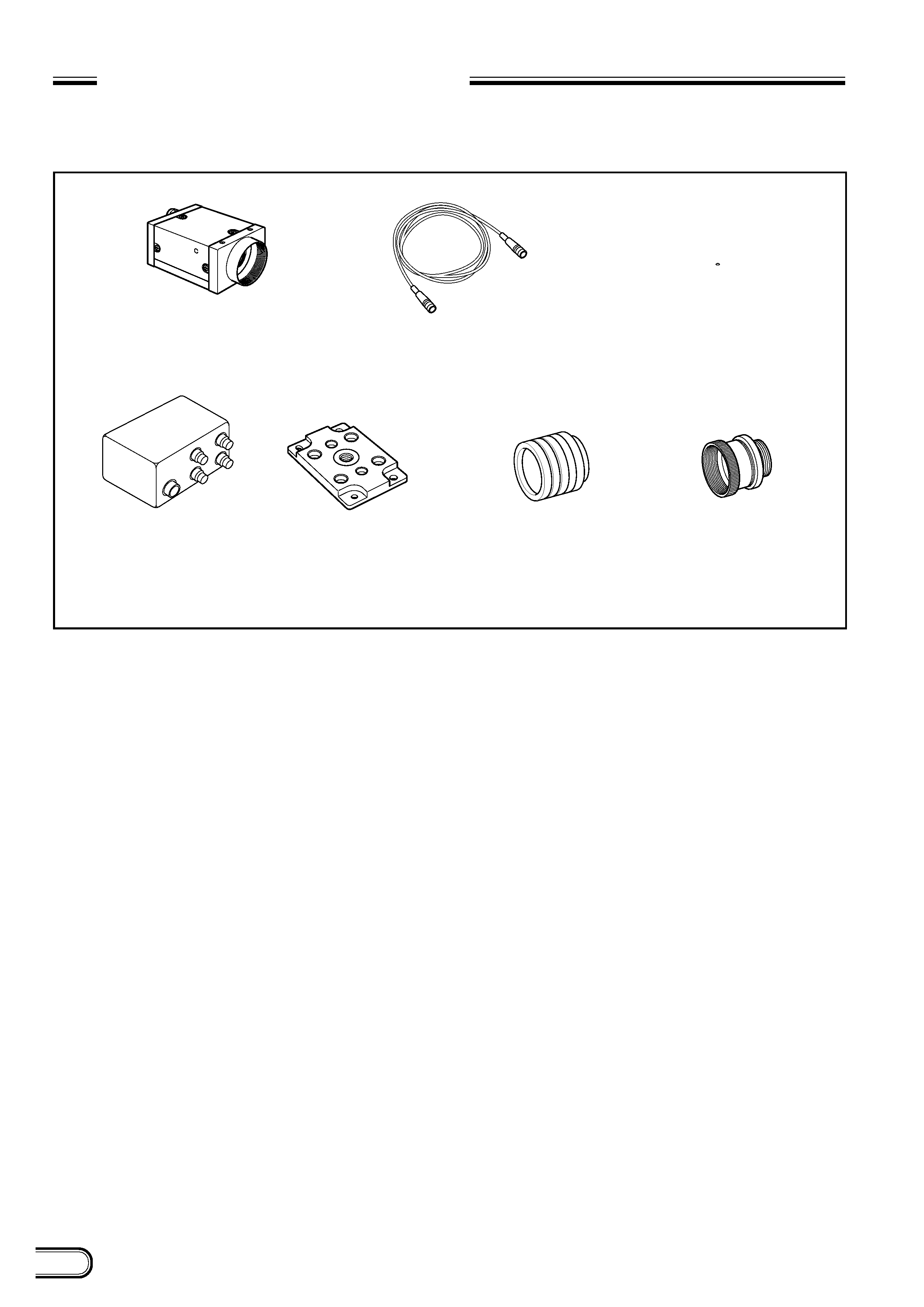
SYSTEM CONFIGURATION
The components making up the system based on XC-ST70/ST70CE video camera are as follows.
Tripod adaptor
VCT-ST70I (Isolated type)
Close-up ring kit
LO-77ERK
C-mount lenses
VCL-50Y-M
VCL-25Y-M
VCL-16Y-M
VCL-12YM
VCL-08YM
Junction box
JB-77
Video camera module
XC-ST70/70CE
Camera adaptor
DC-700/700CE
Camera cables
CCXC-12P02N (2 m)
CCXC-12P05N (5 m)
CCXC-12P10N (10 m)
CCXC-12P25N (25 m)
3
XC-ST70/70CE
MAIN SPECIFICATIONS
Image pickup device: 2/3-inch interline transfer CCD
Number of effective pixels
XC-ST70:
768(H)
x 494(V)
XC-ST70CE:
752(H)
x 582(V)
CCD horizontal driving frequency
XC-ST70:
14.318 MHz
XC-ST70CE:
14.187 MHz
CCD vertical driving frequency
XC-ST70:
15.734 kHz
XC-ST70CE:
15.625 kHz
Signal system
EIA/CCIR
Cell size
XC-ST70:
11.6(H)
x 13.5(V) um
XC-ST70CE:
11.6(H)
x 11.2(V) um
Lens mount
C-mount
Flange back
17.526 mm
Synchronization system
Internal/external
(Selected automatically.)
External sync input/output
HD/VD (2 to 5 Vp-p)
VS (Sync level: 0.3 Vp-p +0.3 V )
0.15 V
*
Automatically selected according
to the existence of an input signal
when the selection switch on the
rear panel is set to EXT.
Allowable frequency deviation of external synchronization
± 1 %
(in horizontal synchronous frequency)
Jitter
Within
± 50 nsec
Scanning system
2:1 interlacing
Non-interlacing
(during external sync input)
Horizontal resolution
XC-ST70:
570 TV lines
XC-ST70CE:
560 TV lines
Sensitivity
400 lx F8 ( = ON, 0 dB)
S/N ratio
XC-ST70:
60 dB
XC-ST70CE:
58 dB
Minimum subject illuminance
0.3 lx (F1.4, AGC ON)
Gain
AGC/Manual/Fixed
(Can be selected using the switch
on the rear panel.)
Gamma correction
ON/OFF
(Can be selected using the switch
on the rear panel.)
Electronic shutter
XC-ST70:
1/100 to 1/10,000 seconds
XC-ST70CE:
1/120 to 1/10,000 seconds
External trigger shutter
XC-ST70:
1/4 to 1/10,000 seconds
XC-ST70CE:
1/4 to 1/8,000 seconds
*
Set using the DIP switch on the rear panel, or
continuously variable with the trigger pulse
width.
Supply voltage
+12 VDC (
±10%)
Power consumption
2.1 W
Operating temperature 5 °C to +45 °C
Storage temperature 30 °C to +60 °C
Performance assurance temperature
0 °C to +40 °C
Operating humidity
20 to 80 % (Non-condensing)
Storage humidity
20 to 95 % (Non-condensing)
Vibration resistance
10G
(For 20 minutes in the X, Y, and Z
directions at 20 to 200 Hz)
Shock resistance
70G
Outside dimensions
44(W)
x 29(H) x 57.5(D) mm
Weight
105 g
Standards
UL1492, FCC Class A Digital
Device, and CE (EN50081-2 +
EN50082-2)
Other
Restart Reset function frame or
field integration can be selected.
Conforms to new 12-pin EIAJ.
Accessories
Lens mount cap (1)
Instruction Manual (1)
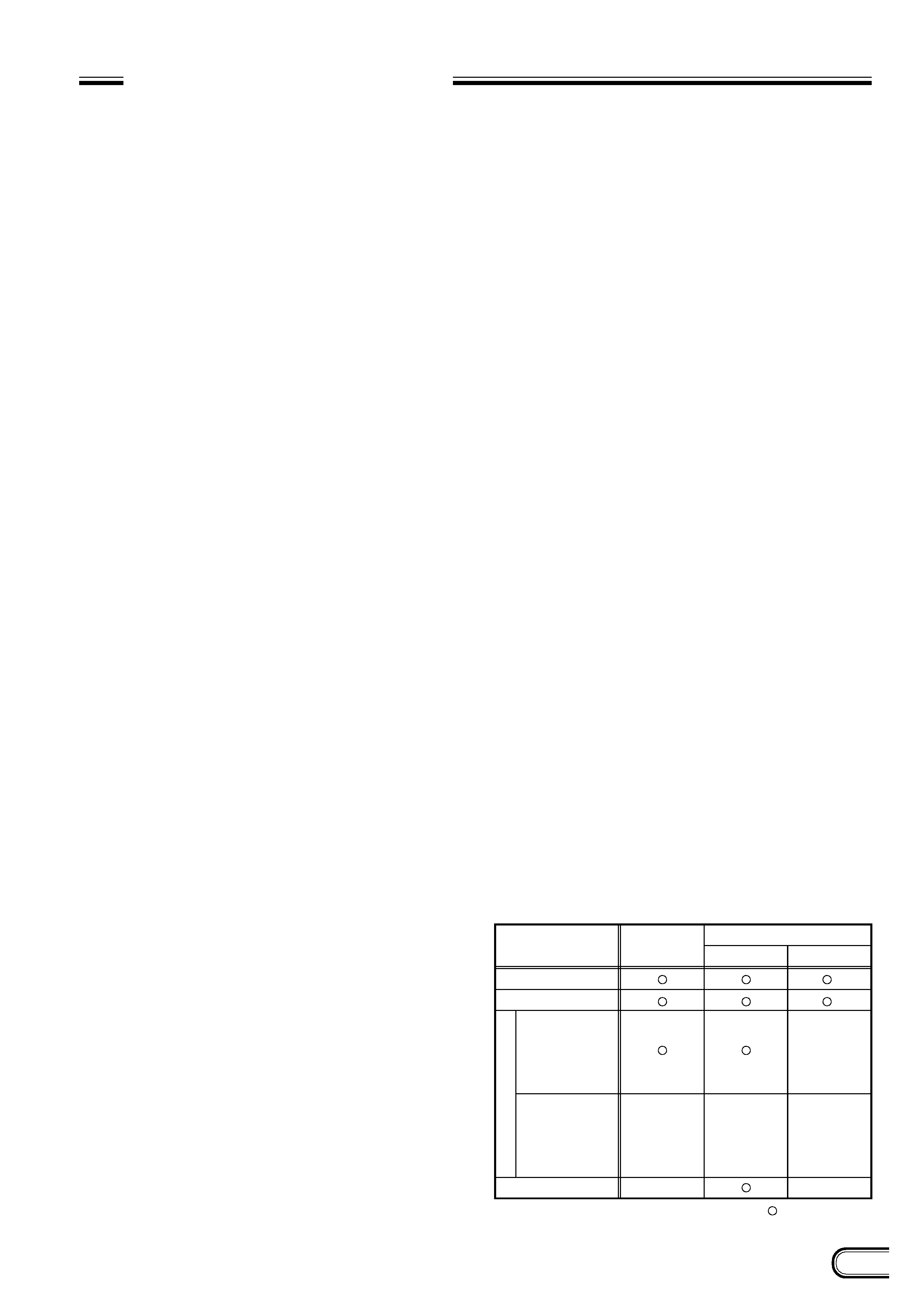
External synchronization for each mode
Mode
Normal
Normal shutter
Restart Reset
Mode 1
non-reset
External
trigger
shutter
Mode 2
reset
Trigger signal
generates an
internal VD
(single) signal.
Internal sync
External sync
HD/VD
×
: Can be used.
×: Cannot be used.
VS
×
×
×
×