CCD B/W CAMERA MODULE
XC-ES50/50CE
XC-ES30/30CE
XC-EI50/50CE
XC-EI30/30CE
User's
Guide
(Ver. 1.0) -- English --

XC-E series
Table of Contents
OUTLINE ................................................................................................................. 1
MAIN FEATURES .................................................................................................... 1
SYSTEM CONFIGURATION ................................................................................... 2
SPECIFICATIONS COMPARISON .......................................................................... 2
MAIN SPECIFICATIONS ......................................................................................... 3
CONNECTION DIAGRAM ....................................................................................... 4
LOCATION OF PARTS AND OPERATION ............................................................. 5
PHASE CONDITIONS OF EXTERNAL SYNCHRONIZATION ................................ 6
ELECTRONIC SHUTTER ........................................................................................ 7
RESTART RESET (R.R) ........................................................................................ 11
FRAME IMAGE OUTPUT WITH STROBE LIGHT ................................................ 13
OUTPUT WAVEFORM TIMING CHART (XC-ES50/EI50/ES30/EI30(EIA)) .......... 14
SENSOR READ CLOCK TIMING CHART ............................................................ 18
TIMING CHART OF EXTERNAL TRIGGER SHUTTER - MODE 1 ....................... 22
TIMING CHART OF EXTERNAL TRIGGER SHUTTER - MODE 2 ....................... 28
DIMENSIONS ........................................................................................................ 30
SPECTRAL RESPONSE CHARACTERISTICS .................................................... 31
VARIOUS LENS SELECTION ............................................................................... 35

1
XC-E series
OUTLINE
The XC-ES30/30CE, XC-ES50/50CE, XC-EI30/30CE, and XC-EI50/50CE are industrial black-and-white video camera
modules, each using a 1/3- or 1/2-inch IT CCD. The 1/3- and 1/2-inch C mount commonly used in industrial applications
implements compact size and lightweight. Switching of each mode on the rear panel, which has been installed from
the XC-ST series, is followed to provide improved operability. The XC-EI series uses a CCD which is sensitive on a
near infrared area to capture a clear image even in low-intensity illumination. As with the existing devices, the XC-
ES30/30CE, XC-ES50/50CE, XC-EI30/30CE, and XC-EI50/50CE incorporate significant shock and vibration resistance
to support installation on FA equipment.
MAIN FEATURES
1/3" and 1/2" IT CCD
A CCD sensitive on a near infrared area is used for the XC-EI series.
External trigger shutter function
(XC-ES50/ES30, XC-EI50/EI30: 1/4 to 1/10,000 seconds,
XC-ES50CE/ES30CE, XC-EI50CE/EI30CE: 1/4 to 1/8,000 seconds)
Restart Reset (R.R) function
Inputting HD and VD signals (2 VD or more) continuously from the outside can catch one image at arbitrary time
and control the stored CCD.
This function is used for long exposures and strobe with frame image output.
Synchronization system: Internal/external HD/VD
Inputting an HD/VD signal from the outside automatically establishes external synchronization.
This function is effective for controlling multiple cameras efficiently from the external system.
Setting each mode on rear panel
The setting of each mode can be changed by the DIP switch.
Almost all switches are located on the rear panel. This feature permits easy setting after equipment is installed.
Compact and lightweight
Compared to the existing devices, the size and weight are reduced widely.
Each of the XC-ES30/30CE, XC-ES50/50CE, XC-EI30/30CE, and XC-EI50/50CE can be used in applications
using two-piece cameras.
C-mount
Excellent shock and vibration resistance
2
XC-E series
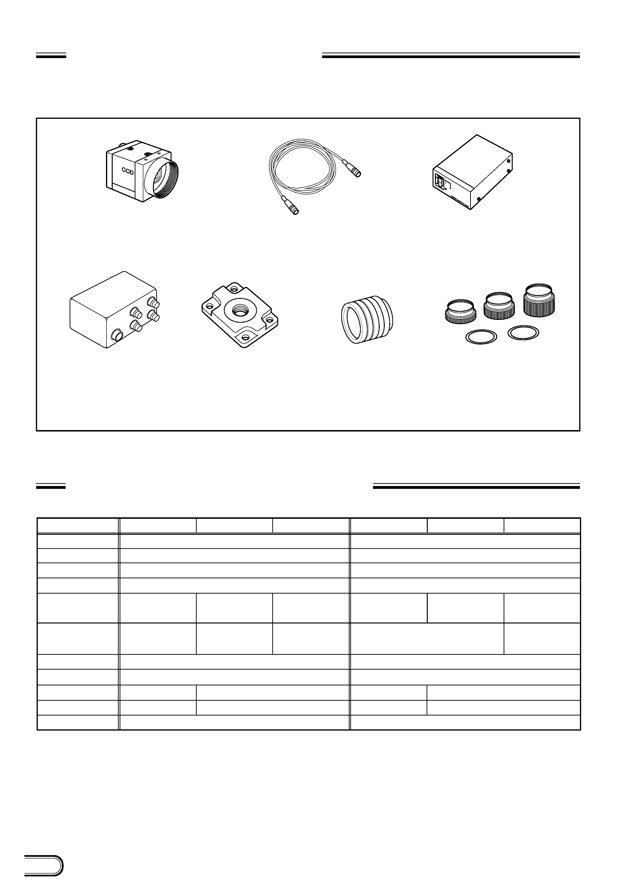
SYSTEM CONFIGURATION
The components making up the system based on XC-E series video camera are as follows.
SPECIFICATIONS COMPARISON
Image pickup device
Number of effective pixels
Lens mount
Scanning system
Sensitivity
Minimum
illuminance *
Normal shutter
External trigger shutter
Dimensions
Mass
Shock resistance
*F1.4, =ON, MAX GAIN
C mount
2:1 interlaced
400 lx F8
(
=ON, 0dB)
0.3 lx
1/4 to 1/10,000 seconds
44 (W) x29 (H) x57.5 (D) mm
105 g
10G (in the X, Y, and Z directions at 20 to 200 Hz)
1/2"IT CCD
768 (H) x494 (V)
400 lx F5, 6
(
=ON, Min Gain IR
without IR cut filter)
0.3 lx
0.1 lx
29 (W) x29 (H) x32 (D) mm
44 (W) x29 (H) x57.5 (D) mm
29 (W) x29 (H) x32 (D) mm
50 g (approx.)
1/3"IT CCD
768 (H) x494 (V)
C mount
2:1 interlaced
400 lx F8
(
=ON, 0dB)
0.3 lx
1/4 to 1/10,000 seconds
1/100 to 1/10,000 seconds
1/100 to 1/10,000 seconds
105 g
10G (in the X, Y, and Z directions at 20 to 200 Hz)
400 lx F8
(
=ON, Min Gain IR
without IR cut filter)
400 lx F11
(
=ON, Min Gain IR
without IR cut filter)
400 lx F8
(
=ON, Min Gain IR
without IR cut filter)
0.2 lx
50 g (approx.)
XC-ES50
XC-EI50
XC-ST50
XC-ES30
XC-EI30
XC-ST30
Tripod adaptor
VCT-333I (Isolated type)
Close-up ring kit
LO-77ERK
C-mount lenses
VCL-08YM
VCL-12YM
VCL-16Y-M
VCL-25Y-M
VCL-50Y-M
Junction box
JB-77
Video camera module
XC-ES50/50CE
XC-ES30/30CE
XC-EI50/50CE
XC-EI30/30CE
Camera adaptor
DC-700/700CE
Camera cables
CCXC-12P02N (2 m)
CCXC-12P05N (5 m)
CCXC-12P10N (10 m)
CCXC-12P25N (25 m)

3
XC-E series
MAIN SPECIFICATIONS
Image pickup device
XC-ES50/50CE, XC-EI50/50CE:
1/2-inch interline transfer CCD
XC-ES30/30CE, XC-EI30/30CE:
1/3-inch interline transfer CCD
Number of effective pixels
XC-ES50/EI50, XC-ES30/EI30:
768 (H)x494 (V)
XC-ES50CE/EI50CE, XC-ES30CE/EI30CE:
752 (H)x582 (V)
CCD horizontal driving frequency
XC-ES50/EI50, XC-ES30/EI30:
14.318 MHz
XC-ES50CE/EI50CE, XC-ES30CE/EI30CE:
14.187 MHz
CCD vertical driving frequency
XC-ES50/EI50, XC-ES30/EI30:
15.734 kHz
XC-ES50CE/EI50CE, XC-ES30CE/EI30CE:
15.625 kHz
Signal system
EIA/CCIR
Cell size
XC-ES50/EI50:
8.4 (H)x9.8 (V) µ m
XC-ES50CE/EI50CE:
8.6 (H)x8.3 (V) µ m
XC-ES30/EI30:
6.35 (H)x7.4 (V) µ m
XC-ES30CE/EI30CE:
6.5 (H)x6.25 (V) µ m
Lens mount
C-mount
Flange back
17.526 mm
Synchronization system
Internal/external
(Selected automatically)
External sync input/output
HD/VD (2 to 5 Vp-p)
*
Automatically selected according
to the existence of an input signal
when the selection switch on the rear
panel is set to EXT.
Allowable frequency deviation of external synchronization
± 1 %
(in horizontal synchronous frequency)
Jitter
Within
± 50 nsec
Scanning system
2:1 interlacing
Non-interlacing
(during external sync input)
Horizontal resolution
XC-ES50/EI50, XC-ES30/EI30:
570 TV lines
XC-ES50CE/EI50CE, XC-ES30CE/EI30CE:
560 TV lines
Sensitivity
XC-ES50/50CE: 400 lx F5,6 (
=ON, MIN Gain,
without IR cut filter)
XC-ES30/30CE: 400 lx F4 (
=ON, MIN Gain,
without IR cut filter)
XC-EI50/50CE: 400 lx F11 (
=OFF, MIN Gain,
without IR cut filter)
XC-EI30/30CE: 400 lx F8 (
=ON, MIN Gain,
without IR cut filter)
S/N ratio
60dB
Minimum illuminance
XC-ES50/50CE, XC-ES30/30CE:
0.3 lx (F1.4
=ON, MAX Gain,
without IR cut filter)
XC-EI50/50CE: 0.1 lx (F1.4
=ON, MAX Gain,
without IR cut filter)
XC-EI30/30CE: 0.2 lx (F1.4 (
=ON, MAX Gain,
without IR cut filter)
Gain
AGC/Manual (Can be selected using
the switch on the rear panel.)
Gamma correction
ON/OFF (Can be selected
using the switch on the rear
panel.)
Electronic shutter
XC-ES50/EI50, XC-ES30/EI30:
1/100 to 1/10,000 seconds
XC-ES50CE/EI50CE, XC-ES30CE/EI30CE:
1/120 to 1/10,000 seconds
External trigger shutter
XC-ES50/EI50, XC-ES30/EI30:
1/4 to 1/10,000 seconds
XC-ES50CE/EI50CE, XC-ES30CE/EI30CE:
1/4 to 1/8,000 seconds
*
Set using the DIP switch on the rear panel, or
variable with the trigger pulse width.
Supply voltage
+12 VDC (+9.0V to 16V)
Power consumption
XC-ES30/30CE, XC-EI30/30CE:
1.4W
XC-ES50/50CE, XC-EI50/50CE:
1.6W
Operating temperature
5 °C to +45 °C
Storage temperature
20 °C to +60 °C
Performance assurance temperature
0 °C to +30 °C
Operating humidity
20 to 80 % (Non-condensing)
Storage humidity
20 to 95 % (Non-condensing)
Vibration resistance
10G (For 20 minutes in the X, Y,
and Z directions at 20 to 200 Hz)