SERVICE MANUAL
AUX-IN SELECTOR
US Model
Canadian Model
AEP Model
UK Model
E Model
SPECIFICATIONS
XA-300
Ver 1.1 2002.08
9-873-500-12
Sony Corporation
2002H0500-1
e Vehicle Company
C
2002.08
Published by Sony Engineering Corporation
FEATURES
Power requirement
12 V DC car battery
(negative earth)
Current drain
340 mA
Operating temperature 10
°C to +55°C
(14
° F to 131° F)
Dimensions
Approx. 148
× 34 × 101 mm
(5 7/8
× 1 3/8 × 4 in.)
(w/h/d)
Mass
Approx. 470 g (1 lb 16 oz.)
Supplied accessories
BUS cable
RCA pin cord
Velcro tape
Design and specifications are subject to change
without notice.
The XA-300 is an external selector for connecting
a Sony BUS system-compatible CD/MD device
or a non-compatible portable device (such as a
DVD player, MD Walkman, or laptop computer)
to a Sony BUS system-compatible master unit.
Enjoy the sound of portable media in your car.
WALKMAN is trademark of Sony Corporation.

2
XA-300
TABLE OF CONTENTS
1.
SERVICING NOTES ................................................ 2
2.
GENERAL ................................................................... 3
3.
DIAGRAMS
3-1. Note for Printed Wiring Board and
Schematic Diagram .........................................................
3
3-2. Printed Wiring Board ......................................................
4
3-3. Schematic Diagram .........................................................
5
3-4. IC Pin Function Description ...........................................
6
4.
EXPLODED VIEW ................................................... 7
5.
ELECTRICAL PARTS LIST ............................... 8
Notes on chip component replacement
· Never reuse a disconnected chip component.
· Notice that the minus side of a tantalum capacitor may be dam-
aged by heat.
SECTION 1
SERVICING NOTES
Connection to repair
This set is controled by master unit with serial communication.
Therefore, to operate this set, connect master unit as shown below.
Connecting via USB
This set can be connected via its USB connector to a parsonal
computer with USB port.
SET
BUS CONTROL
OUTPUT terminal
BUS CONTROL
INPUT terminal
MASTER UNIT
· Compatible operating systems
Windows® 98 Second Edition/
Windows® Me/Windows® 2000
(Windows® 2000 recommended)
Mac OS 8.6 or later
(Mac OS 9.0 or later recommended)
XA-300
3
3
SECTION 2
GENERAL
3-1.
NOTE FOR PRINTED WIRING BOARD AND SCHEMATIC DIAGRAM
3
LR
AUDIO
AUDIO
AUDIO
AUDIO
HEADPHONE
MIN
MAX
L
VOL
R
L
R
OUTPUT
AUX IN 1
AUX IN 2
USB
CONTROL
CONTROL
LR
INPUT
MIN
VOL
MAX
1
1
2
2
3
4
5
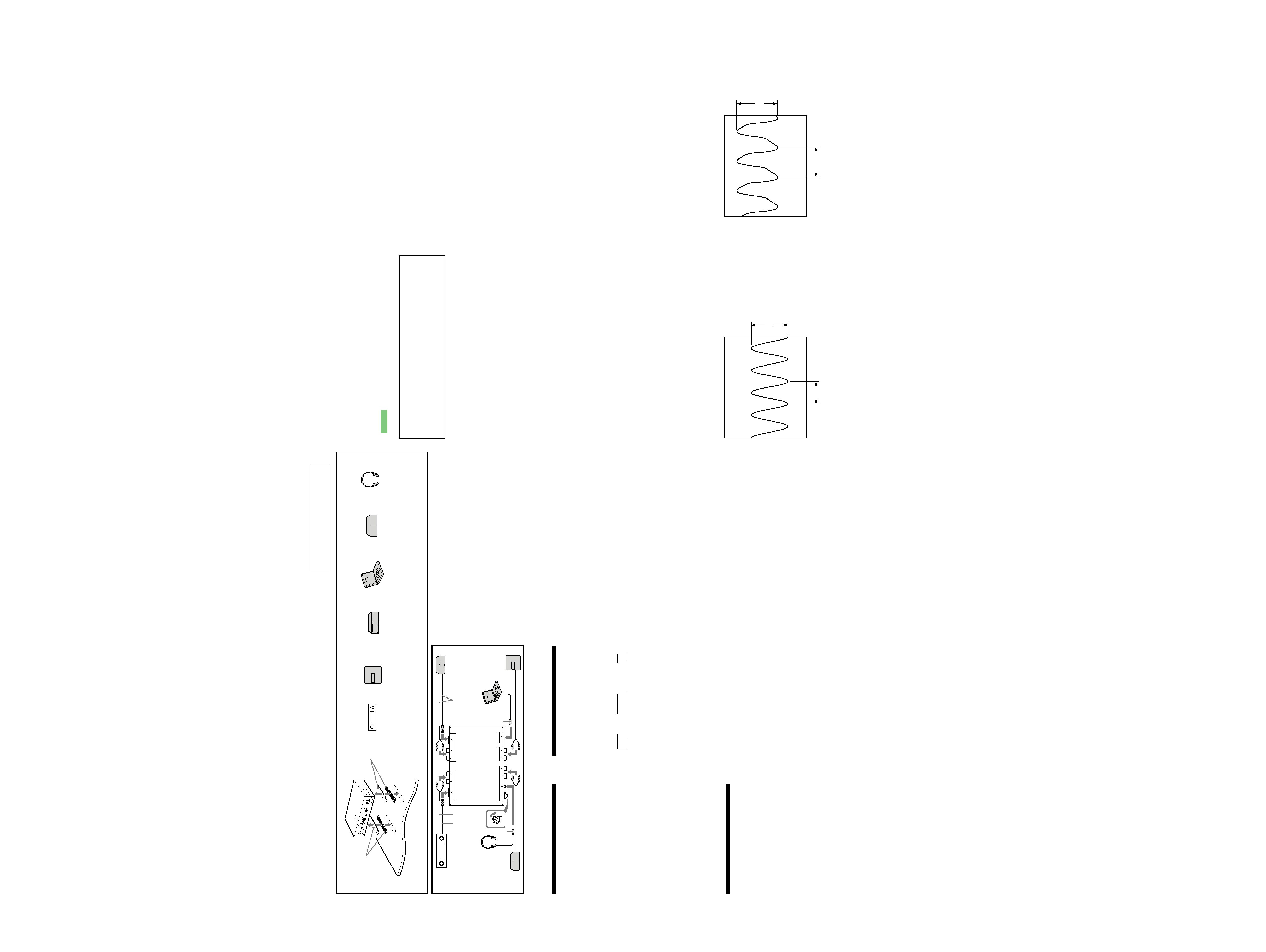
Place the unit under the passenger
seat, etc. (2)
Before installation
·Choose the installation location carefully so
that the unit does not interfere with normal
driving operations.
·Avoid installing the unit where it would be
subject to:
--high temperatures, such as from direct
sunlight or hot air from the heater.
--draft, rain or moisture.
-- dust or dirt.
--magnetic fields.
·Use only the supplied mounting hardware for
a safe and secure installation.
If you have any questions or problems
concerning your unit that are not covered in
this manual, please consult your nearest Sony
dealer.
Stick one piece of the Velcro tape provided to
the bottom of the unit and the other to the
surface of the car where you want to place it
(such as the carpet underneath the passenger
seat) in order to hold the unit in position.
After removing the dust and dirt from the
surface of Velcro tapes, stick them together.
Connection example (3)
1 You can connect the source selector (XA-
C30, etc.) compatible with the Sony BUS
system.
For details, refer to the user's manual for the
source selector you are using.
2 Supplied with the CD/MD changer
3 Volume control for headphones connected
to AUX IN 1.
4 Stereo mini-plug
5 USB connector
· Computer with USB port
· Compatible operating systems
Windows® 98 Second Edition/
Windows® Me/Windows® 2000
(Windows® 2000 recommended)
Mac OS 8.6 or later
(Mac OS 9.0 or later recommended)
Note
Depending on the device to be connected, you
might need to buy a different connector cord.
For further details, read the operating manual of
the device to be connected or ask your local
dealer.
To select a device connected to the
unit by the master unit
1Press (SOURCE) repeatedly until "CD" is
selected.
2Press (MODE) repeatedly until the device
you want to listen to is selected.
Example: Master unit display window
Tip
When you select a Sony BUS system-
compatible device, it will automatically start
playing.
3 Start playing the device selected in 2.
For the playback method of the selected device,
refer to its operating manual.
4 Adjust the volume of the master unit and
selected device.
Notes
· Follow the steps below to play the audio file of
the computer connected to the USB jack of this
unit.
1 Press the MODE button of the master
unit to select "USB."
2 Open the playback software (Windows
Media Player, etc.) on your computer.
3 Play the audio file (MP3,etc.).
After playing the audio file on the computer, if
you select "USB" mode on the display of the
master unit, this unit may not recognize the
signal and sound may not come out.
· As the volume settings of each connected
device may differ, adjust the volume on each
device separately. As the sound output differs
on AUX IN 1 and AUX IN 2, connect the Sony
car audio DVD changer to AUX IN 1, and
connect a portable device (such as MD
WALKMAN, etc.) to AUX IN 2.
· While playing audio file in a device connected
to AUX IN 1, AUX IN 2, or the USB jack on this
unit, do not change any settings of the CD
CUSTOM FILE function. If trouble occurs, press
the SOURCE button again on the master unit
to select the device you want.
B
CD1
B
CD2/AUX1
CD4/USB b
CD3/AUX2 b
SECTION 3
DIAGRAMS
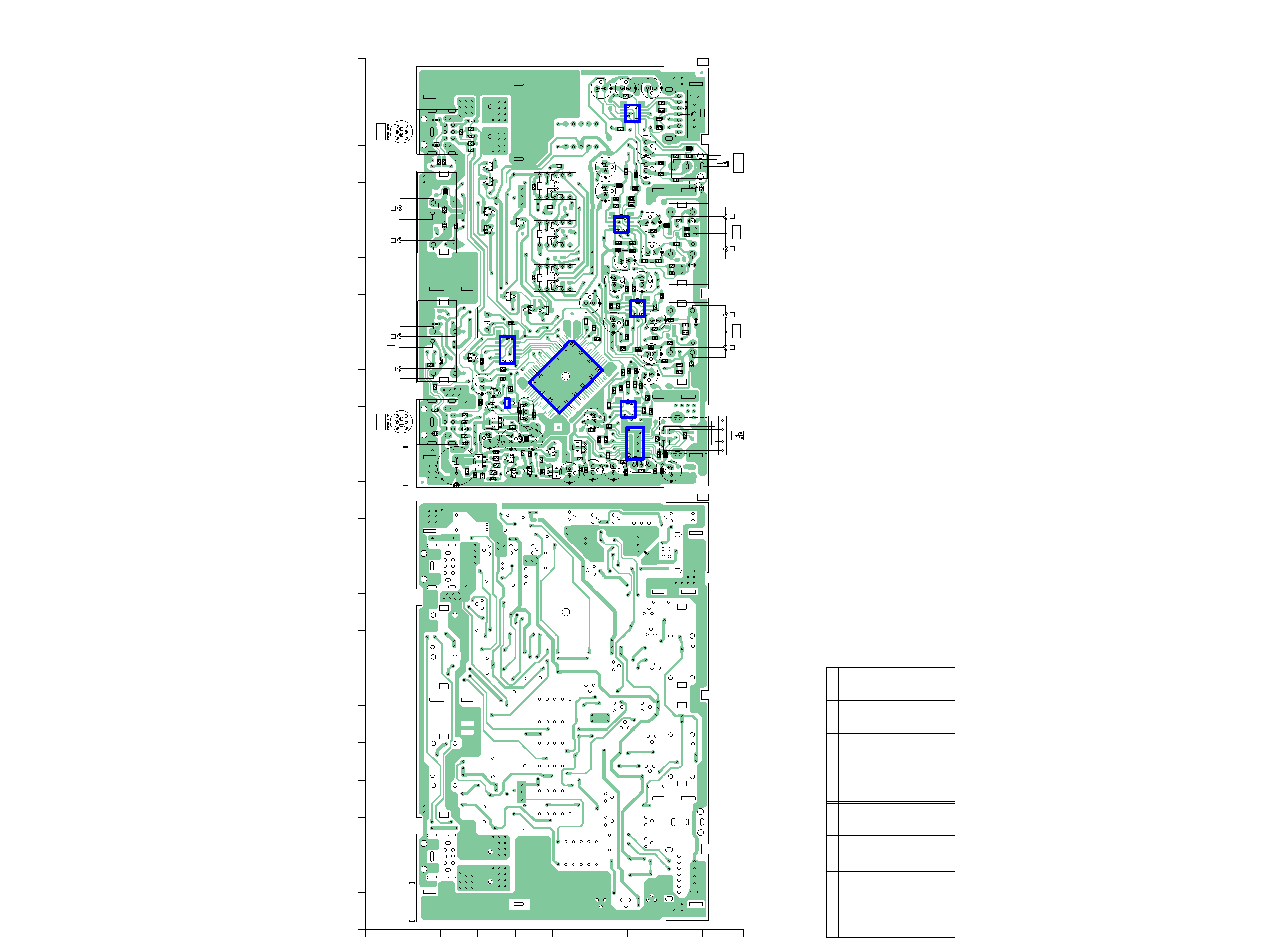
Note on Printed Wiring Board:
· X : parts extracted from the component side.
·
f
: internal component.
·
: Pattern from the side which enables seeing.
(The other layers' patterns are not indicated.)
Caution:
Pattern face side:
Parts on the pattern face side seen from
(Conductor Side)
the pattern face are indicated.
Parts face side:
Parts on the parts face side seen from
(Component Side) the parts face are indicated.
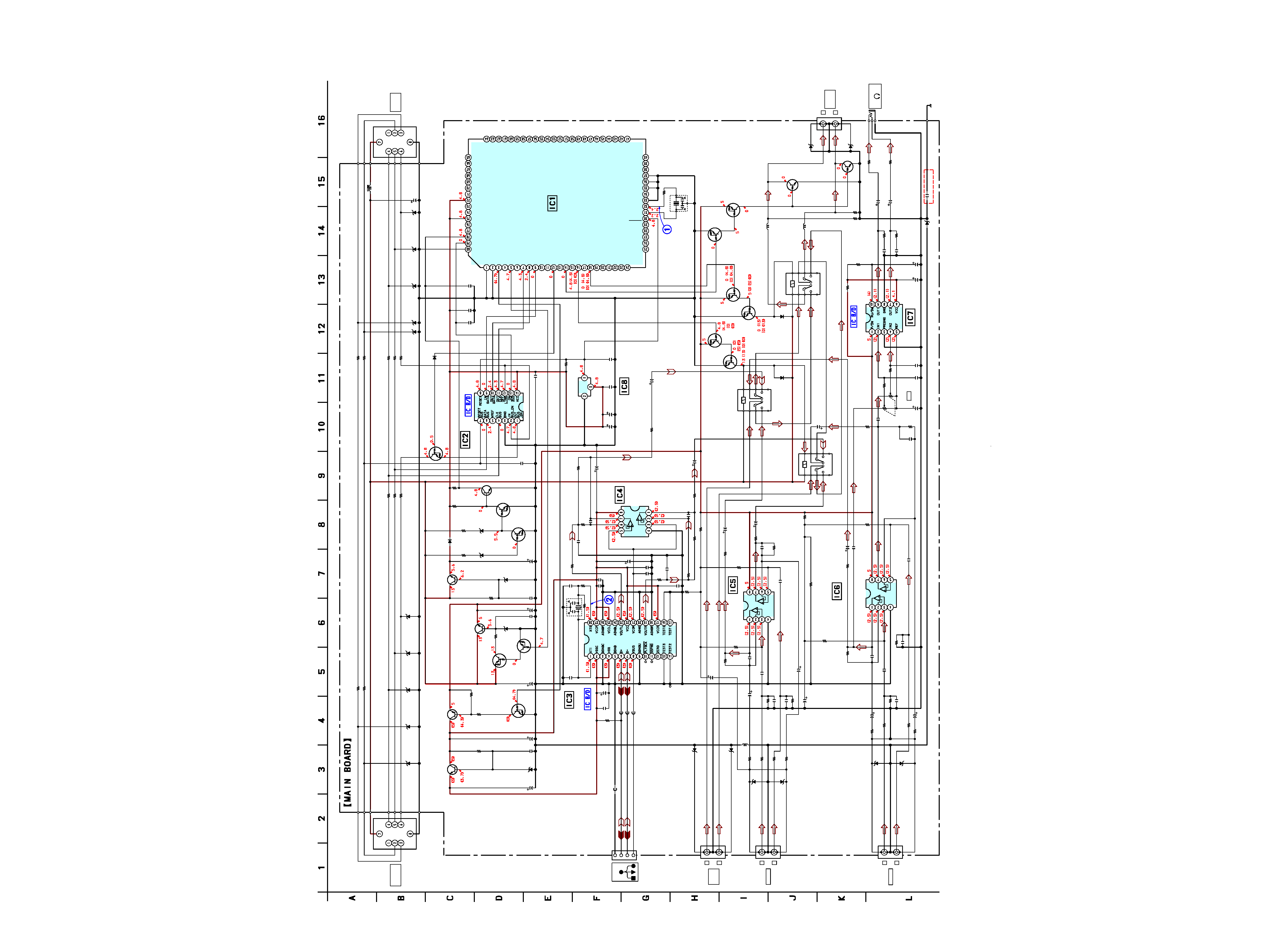
Note on Schematic Diagram:
· All capacitors are in µF unless otherwise noted. pF: µµF
50 WV or less are not indicated except for electrolytics
and tantalums.
· All resistors are in and 1/4 W or less unless otherwise
specified.
·
f
: internal component.
· C : panel designation.
· A : B+ Line.
· H : adjustment for repair.
·Power voltage is dc 14.4V and fed with regulated dc power
supply to master unit.
·Voltages and waveforms are dc with respect to ground
under the condition that master unit is connected.
no mark : CD - C
() : AUX 1
[] : AUX 2
: USB
·Voltages are taken with a VOM (Input impedance 10 M).
Voltage variations may be noted due to normal produc-
tion tolerances.
·Waveforms are taken with a oscilloscope.
Voltage variations may be noted due to normal produc-
tion tolerances.
· Circled numbers refer to waveforms.
· Signal path.
F
: AUDIO
E
: USB IN
j
: USB OUT
·Waveforms
1
IC1 es (XTAL)
3.9 Vp-p
99.5 ns
3.6 Vp-p
83 ns
2
IC3 wk (XTO)
This section is extracted from
instruction manual.
2
Equipment used in illustrations (not supplied)/Equipements utilisés dans les illustrations (non fournis)/Apparecchiature utilizzate nelle illustrazioni (non in
dotazione)/In den Abbildungen gezeigte Komponenten (nicht mitgeliefert)/Geïllustreerde apparatuur (niet meegeleverd)/Equipmento utilizado nas ilustrações
(não fornecido)/µ µ ( )/Utrustning som används i illustrationerna (medföljer inte)/Equipo utilizado
en las ilustraciones (no suministrado)
3
3
Master unit
Appareil principal
Unità principale
Hauptgerät
Master unit
Unidade principal
Huvudenhet
Unidad principal
CD/MD changer
Changeur CD/MD
Cambia CD/MD
CD/MD-Wechsler
CD/MD-wisselaar
Carregador de CD/MD
CD/MD changer
CD/MD-växlare
Cambiador de CD/MD
Headphones
Casque
Cuffie
Kopfhörer
Hoofdtelefoon
Auscultadores
Hörlurar
Auriculares
MD Walkman, etc.
Walkman MD, etc.
MD Walkman, e così via.
MD-Walkman usw.
MD Walkman, enz.
Walkman de MD, etc.
MD Walkman, .
MD Walkman eller liknande
Walkman de MD, etc.
Laptop computer
Ordinateur portable
Computer portatile
Laptop-Computer
Laptop computer
Computador laptop
Bärbar dator
Ordenador portátil
DVD player, etc.
Lecteur DVD, etc.
Lettore DVD, e così via.
DVD-Player usw.
DVD-speler, enz.
Leitor de DVD, etc.
DVD player, .
DVD-spelare eller liknande
Reproductor de DVD, etc.
XA-300
4
4
3-2.
PRINTED WIRING BOARD
CN102
C106
C301
C516
C515
C716
C715
C703
C708
C605
C606
C513
C504
C102
C303
C108
C104
C101
C712
C506
C107
C721
RY103
RY102
RY101
C607
C608
C717
C718
C711
C722
C611
X102
X101
CN106
CN105
CN104
CN108
RV101
R201
D104
Q302
D102
Q301
Q102
D103
IC2
Q101
R407
R406
R408
R410
R713
R714
R712
C710
C709
C714
C713
C702
C706
C701
C704
C707
C603
C602
C503
C505
C509
C511
C510
C507
C302
C103
C109
C110
C111
C514
C604
C601
R604
R610
R612
R611
R614
R613
R607
R606
R608
R605
R
6
0
2
R601
R609
R720
R722
R721
R719
R705
R702
R706
R709
R704
R710
R716
R718
R717
R715
R403
R404
R405
R401
R402
R143
R103
R301
R302
R505
R503
R502
R711
R708
IC6
IC5
IC7
Q803
Q801
Q902
Q901
Q804
Q802
Q402
Q104
Q103
IC8
Q201
Q303
R409
C705
C719
C720
C609
C
6
1
0
C518
C517
R101
C105
R102
Q203
Q202
R204
R203
R501
R507
R508
C512
R512
R510
R506
R509
R513
R303
R603
R511
R707
R701
C113
C114
C115
C112
R903
R904
R703
ZD403
ZD404
ZD405
ZD402
ZD401
D101
ZD407
ZD406
ZD408
ZD410
ZD409
ZD103
ZD104
ZD102
ZD101
ZD301
IC1
R514
L901
L902
Q903
Q904
IC3
IC4
ZD901
ZD902
ZD601
ZD602
ZD604
ZD603
ZD701
ZD702
R202
C501
C502
41
64
1
24
R504
FB501
ZD703
C730
INPUT
CONTROL
CN101
OUTPUT
CONTROL
8
32
1
7
65
4
3
2
1
CN103
R
L
AUX IN 2
AUDIO
R
L
AUX IN 1
AUDIO
L
R
INPUT
AUDIO
L
R
OUTPUT
AUDIO
8
7
32
1
65
4
CN107
HEADPHONE
i
VOL
MAIN BOARD
(CONDUCTOR SIDE)
1-682-009-
11
(11)
MAIN BOARD (COMPONENT SIDE)
1-682-009-
11
(11)
B
C
D
E
F
G
H
I
J
1
2
3
4
5
6
7
8
9
10
11
12
13
14
15
16
17
18
19
20
21
22
23
A
USB
(AEP, UK)
D101
E-18
D102
E-20
D103
D-15
D104
D-13
IC1
F-15
IC2
D-16
IC3
H-13
IC4
G-14
IC5
H-17
IC6
G-19
IC7
H-22
IC8
D-15
Q101
D-13
Ref. No.
Location
Ref. No.
Location
Ref. No.
Location
Ref. No.
Location
Q102
D-14
Q103
D-13
Q104
D-15
Q201
E-13
Q202
D-13
Q203
D-13
Q301
F-13
Q302
F-13
Q303
F-13
Q402
C-16
Q801
E-17
Q802
E-17
Q803
D-17
Q804
E-19
Q901
D-19
Q902
D-20
Q903
D-21
Q904
D-21
ZD101
E-14
ZD102
D-13
ZD103
D-13
ZD104
D-13
ZD301
F-13
ZD401
B-14
ZD402
B-14
ZD403
C-14
ZD404
C-14
ZD405
C-14
ZD406
B-22
ZD407
B-22
ZD408
C-22
ZD409
C-22
ZD410
C-22
ZD601
B-17
ZD602
C-16
ZD603
I-17
ZD604
I-16
ZD701
I-19
ZD702
I-18
ZD703
I-20
ZD901
C-20
ZD902
C-19
· Semiconductor Location
Ver 1.1
XA-300
5
5
3-3.
SCHEMATIC DIAGRAM · See page 3 for Waveforms.
· See page 6 for IC Block Diagram.
C601
R102
R202
R301
R722
RY103
C501
C607
R701
CN108
ZD902
ZD901
C715
C716
R904
R903
R715
R716
C714
ZD703
Q902
Q901
C712
C711
R714
C713
R712
Q803
C110
C109
IC8
R143
C113
C114
C111
D103
ZD410
ZD409
ZD408
ZD407
ZD406
C112
C115
R204
C108
R509
C513
R508
C515
R513
RY101
RY102
C707
C706
R711
C720
R721
C704
C703
R704
R719
R720
C610
R609
C604
R610
C606
R613
C605
R611
R604
C514
R512
R511
R612
C518
C511
R510
C509
C506
R507
C512
C517
R506
C105
C106
R101
ZD103
ZD104
Q202
R203
D104
R201
ZD101
C103
C102
ZD102
ZD405
ZD404
ZD403
ZD402
ZD401
R302
R303
ZD301
C301
C302
C303
ZD601
ZD602
R601
R602
R606
R607
ZD604
ZD603
ZD701
ZD702
R707
C718
R713
C719
C701
R708
C705
C702
R705
C717
R702
R706
C611
R614
R603
C609
C722
C608
C603
R608
C602
R605
R502
C503
C504
C104
Q104
C516
Q101
Q102
Q301
Q302
C101
R710
C708
C510
Q904
Q903
IC7
RV101
RV101
D102
D101
C107
IC2
IC4
Q203
Q201
Q103
IC5
IC6
CN103
CN104
CN105
CN106
Q804
Q802
Q801
C505
C507
IC3
C502
X102
Q402
Q303
L102
C709
C710
L101
X101
CN107
CN102
R401
R402
R403
R404
R405
R406
R407
R408
R409
R410
R103
C721
CN101
FB501
R503
R504
R505
R514
R501
IC1
R703
R709
L901
L902
R718
R717
C730
470p
4.7k
1k
4.7k
10k
18p
47 16V
1k
2P
UDZ-TE-17-3.9B
UDZ-TE-17-3.9B
220
6.3V
220
6.3V
10k
10k
2.2
2.2
0.1
UDZ-TE-17-3.9B
DTA114EK-T146
DTC114EK-T146
47
16V
220
6.3V
470
0.1
4.7k
DTA144EK-T146
0.1
0.1
XC61AN4302MR
47k
0.1
0.1
0.1
MA111-TX
UDZ-TE-17-6.2B
UDZ-TE-17-6.2B
UDZ-TE-17-6.2B
UDZ-TE-17-6.2B
UDZ-TE-17-6.2B
0.1
0.22
47k
47
16V
100
10
16V
12k
10
16V
100
1
470p
4.7k
1
10k
1
10
16V
100
10k
10k
1
6.8k
470p
100
10
16V
10k
10
16V
10k
100
330p
12k
3.9k
10k
1800p
0.1
12k
0.1
10
16V
3.9k
330p
1800p
12k
0.1
47
16V
10k
UDZ-TE-17-18B
UDZ-TE-17-7.5B
DTC144EK-T146
47k
MA111-TX
1k
UDZ-TE-17-5.6B
0.1
47
16V
UDZ-TE-17-6.2B
UDZ-TE-17-6.2B
UDZ-TE-17-6.2B
UDZ-TE-17-6.2B
UDZ-TE-17-6.2B
UDZ-TE-17-6.2B
470
470
UDZ-TE-17-3.9B
47
16V
0.1
220
6.3V
UDZ-TE-17-3.9B
UDZ-TE-17-3.9B
1k
4.7k
4.7k
1k
UDZ-TE-17-3.9B
UDZ-TE-17-3.9B
UDZ-TE-17-3.9B
UDZ-TE-17-3.9B
1k
47 16V
100
1
470p
4.7k
470p
470p
4.7k
47
16V
4.7k
4.7k
220
6.3V
10k
6.8k
1
220
6.3V
47
16V
470p
4.7k
470p
4.7k
1.5k
0.1
10
16V
100
16V
DTC114EK-T146
10
16V
2SD1664-T100-QR
2SD1664-T100-QR
2SB1132-T101-QR
2SD1664-T100-QR
1000
16V
100
10
16V
0.1
DTC314TK
-T-146
DTC314TK
-T-146
LA4536M-TE-R
(2/2)
(1/2)
MA111-TX
MA111-TX
0.047F
5.5V
BA8272F-E2
NJM2100E
(TE2)
DTC114EK
-T146
2SC2412K-T-146R
DTA124EK
-T146
NJM2100E(TE2)
NJM2100E(TE2)
4P
2P
2P
2P
DTC114EK-T146
DTC114EK
-T146
DTA144EK
-T146
0.1
0.1
PCM2702
18p
12MHz
DTA144EK
DTC114EK-T146
220p
220p
10MHz
8P
10
10
10
10
10
10
10
10
10
10
1k
47
16V
8P
1k
1M
CXP83412-054Q
1.8k
1.8k
0
0
0.001
+B
CLK
DATA
BUS_ON
GND
SIRCS
RST
NC
SIRCS
RST
NC
GND
BUS_ON
DATA
CLK
+B
SYSTEM CONTROLLER
OUTPUT
CONTROL
BUS ON SWITCH
BUS INTERFACE
RESET
SIGNAL
GENERATOR
Q901-904
MUTING
DRIVE
Q803,804
RELAY DRIVE
RELAY DRIVE
Q801,802
OUTPUT
AUDIO
HEADPHONE AMP
VOL
BUFFER
VCC
GND
BUFFER
VCC
GND
BUFFER
VCC
GND
Q201-203
BACK UP CHECK
Q103,104
POWER ON
SWITCH
U-COM 5V
REGULATOR
+5V
REGULATOR
USB ON
SWITCH
B+ SWITCH
REGULATOR
+3V
USB D/A
CONVERTER
INPUT
AUDIO
CONTROL
INPUT
NCO
VDD
SUB
CLOCK
SUB
CLOCK
NCO
NCO
NC
BU
CHECK
BUS
ON
NIL
NCO
NCO
NCO
NCO
NCO
NCO
NCO
NCO
NCO
NCO
NCO
NCO
NCO
NCO
NCO
NCO
NCO
NCO
NCO
NCO
NCO
NCO
NCO
NCO
NCO
NCO
NCO
NCO
NCO
NCO
MODE SW
NIL
USB ON
NCO
POWER ON
NCO
BUS CLK
BUS SI
BUS SO
NCO
NCO
NCO
NCO
NCO
NCO
NCO
NCO
NCO
NCO
LINK OFF
ATT
AUDIO SEL1
AUDIO SEL2
AUDIO SEL3
NCO
NCO
NCO
NCO
NCO
NCO
NCO
NCO
VLC1
VLC2
VLC3
VL
GND
XTAL
EXTAL
RESET
L
R
HEADPHONE
AUX2/CD-C
AUX1/USB
AUX2/CD-C
AUX1/USB
AUX1
USB
AUX2
CD-C
AUX1
AUX2
CD-C
USB
V
GRST
(FOR SONY BUS)
GND
D+
D-
VBUS
USB
L
R
AUX IN 2
L
R
L
R
AUX IN 1
(CHASSIS)
(AEP,UK)
450µH
10µH
10µH
220µH
Ver 1.1