Ver 1.0 2001.03
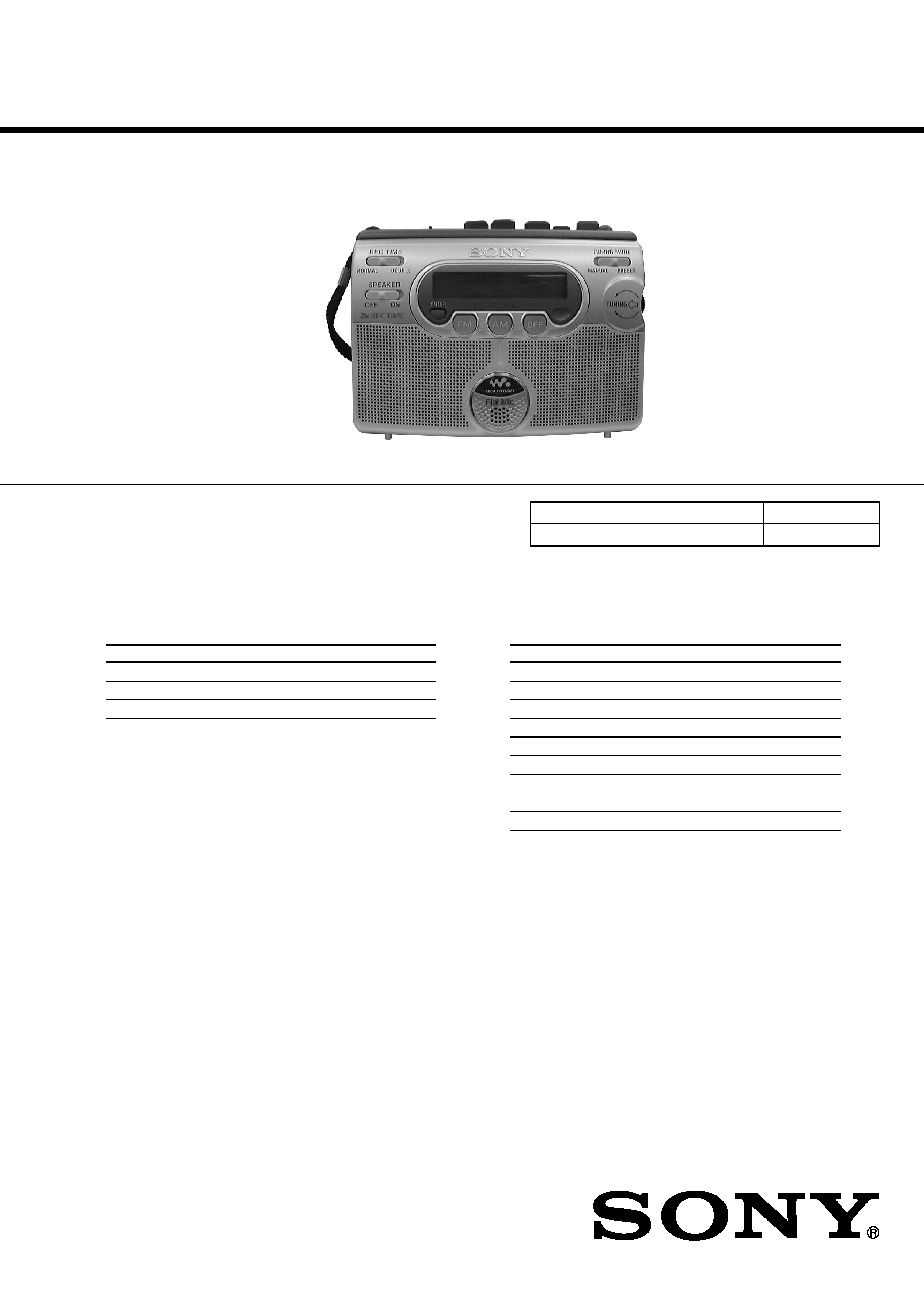
WM-GX400
SERVICE MANUAL
RADIO CASSETTE-CORDER
SPECIFICATIONS
Canadian Model
AEP Model
E Model
Chinese Model
Tourist Model
9-873-087-11
2001C0200-1
© 2001.3
Sony Corporation
Audio Entertainment Group
General Engineering Dept.
Model Name Using Similar Mechanism
NEW
Tape Transport Mechanism Type
MT-WMGX400-175
Frequency range
Area*
FM (MHz)
AM (kHz)
AEP, E, Chineses model
87.5 - 108
531 - 1 602
US, Canadian model
87.5 - 108
530 - 1 710
Tourist model
76 - 90
531 - 1 710
* E: European and other countries, U: Canada, and Central and
South America, J: Japan.
Frequency response
Playback: 40 - 15,000 Hz
Recording: 100 - 8,000 Hz
Input
Microphone (MIC) jack
Output
Headphones (i) jack
Load impedance 8 - 300 ohms
Power requirements
3 V DC batteries R6 (size AA)
× 2
External DC 3V power sources
Dimensions (w/h/d)
Approx. 112.5
× 87.0 × 39.0 mm
(14 1/2
× 3 1/2 × 1 9/16 inches), excl.
projecting parts and controls
Mass
Approx. 190 g (6.8oz) (main unit only)
Supplied accessories
Stereo headphones or earphones (1)
Stereo microphone (1)
Sony dry battery R6P(SR) (2) ("Sony
World Model" only)
Design and specifications are subject to change without notice.
Battery life (Approx. hours)
(EIAJ*)
Sony alkaline LR6 (SG)** Sony R6P (SR)
(using headphones/earphones)
playback
24
6
radio
48
15
mic recording
20
4.5
radio recording
12
3
(using the speakers)
playback
13
3
radio
23
6
radio recording
8.5
1.5
* Measured value by the standard of EIAJ (Electronic Industries
Association of Japan) (using a Sony HF series cassette tape).
** When using Sony LR6 (SG) "STAMINA" alkaline dry
batteries (produced in Japan).
Note
· The battery life may be shorter depending on the operating
condition, the surrounding temperature and battery type.
2
WM-GX400
Flexible Circuit Board Repairing
· Keep the temperature of the soldering iron around 270
°C during
repairing.
· Do not touch the soldering iron on the same conductor of the
circuit board (within 3 times).
· Be careful not to apply force on the conductor when soldering
or unsoldering.
Notes on chip component replacement
· Never reuse a disconnected chip component.
· Notice that the minus side of a tantalum capacitor may be dam-
aged by heat.
TABLE OF CONTENTS
SECTION 1
GENERAL
This section is extracted from
instruction manual.
Specifications ........................................................................... 1
1. GENERAL
Location of Parts and Controls .......................................... 2
2. DISASSEMBLY
2-1. Cabinet (Front)Cabinet (Rear),
"Lid, Cassette ASSY" ............................................... 3
2-2. Main Board ................................................................. 4
2-3. Mechanism Deck ........................................................ 4
2-4. HRPE301 (REC/PB/ERASE head),
M601 (Capstan/reel motor), Belt (AR) ....................... 5
2-5. Display Board ............................................................. 5
3. ADJUSTMENTS
3-1. Mechanical Adjustments ............................................. 6
3-2. Electrical Adjustments ................................................ 6
4. DIAGRAMS
4-1. Explanation of IC Terminals ....................................... 7
4-2. Block Diagrams Tape Section ................................ 8
4-3. Block Diagrams Tuner Section ............................... 9
4-4. Printed Wiring Board Main Section (Side A) ....... 10
4-5. Printed Wiring Board Main Section (Side B) ....... 11
4-6. Schematic Diagram Main Section (1/2) ............... 12
4-7. Schematic Diagram Main Section (2/2) ............... 13
4-8. Printed Wiring Board Display Section (Side A) ... 14
4-9. Printed Wiring Board Display Section (Side B) ... 15
4-10. Schematic Diagram Display Section .................. 16
5. EXPLODED VIEWS
5-1. Cabinet (Rear) Section .............................................. 20
5-2. Cassette Lid Section ................................................. 21
5-3. Mechanism Section-1 (MT-WMGX400-175) .......... 22
5-4. Mechanism Section-2 (MT-WMGX400-175) .......... 23
6. ELECTRICAL PARTS LIST ................................ 24
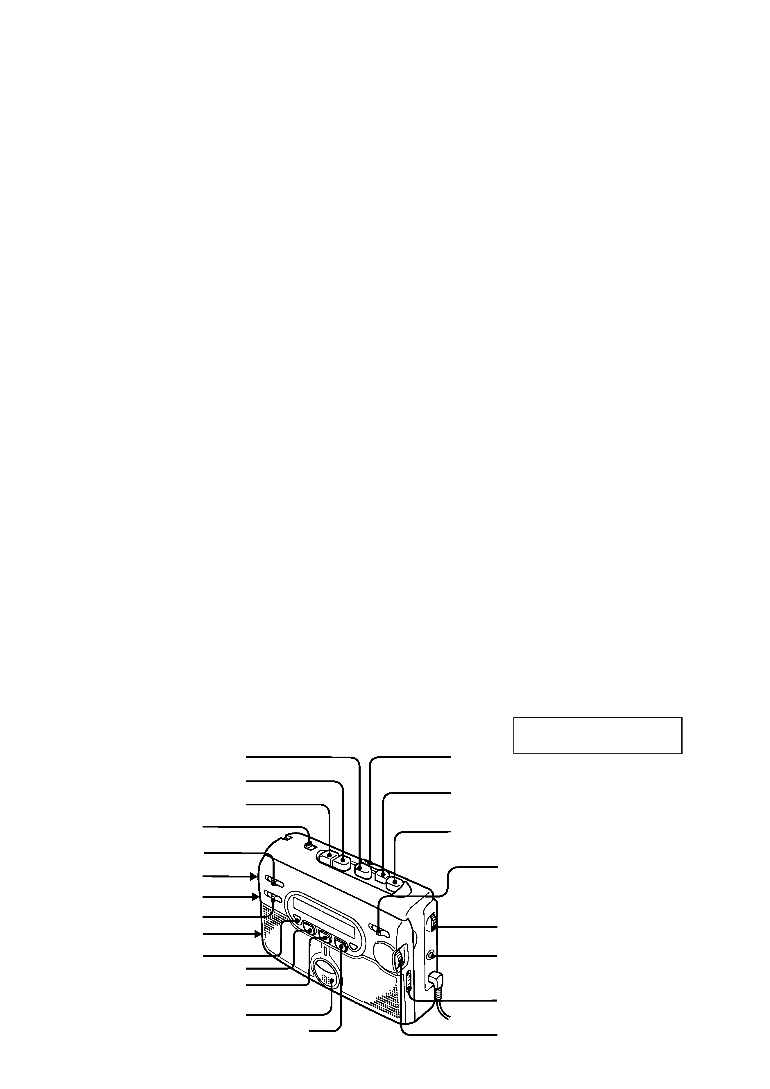
Location of parts and controls
PAUSE
z REC
DIR
REC TIME
AVLS
ISS
DC IN 3V
SPEAKER
i
x STOP
FF/CUE
REW/REVIEW
VOL
FM
AM
OFF
TUNING MODE
TUNING
MIC (PLUG IN POWER)
ENTER
built-in microphone
FM MODE z ST/MONO
FM MODE z DX/LOCAL
(or/ou/oder)
Y PLAY
3
WM-GX400
SECTION 2
DISASSEMBLY
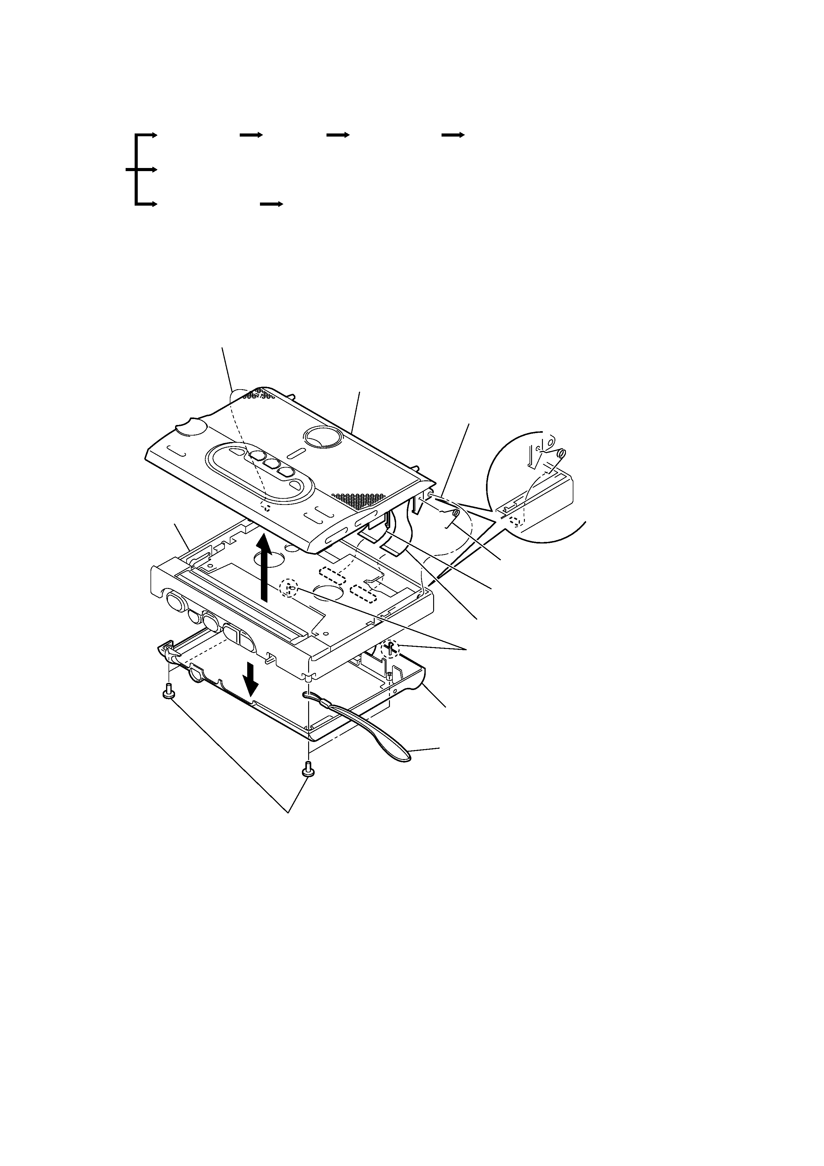
Note : Follow the disassembly procedure in the numerical order given.
· The equipment can be removed using the following procedure.
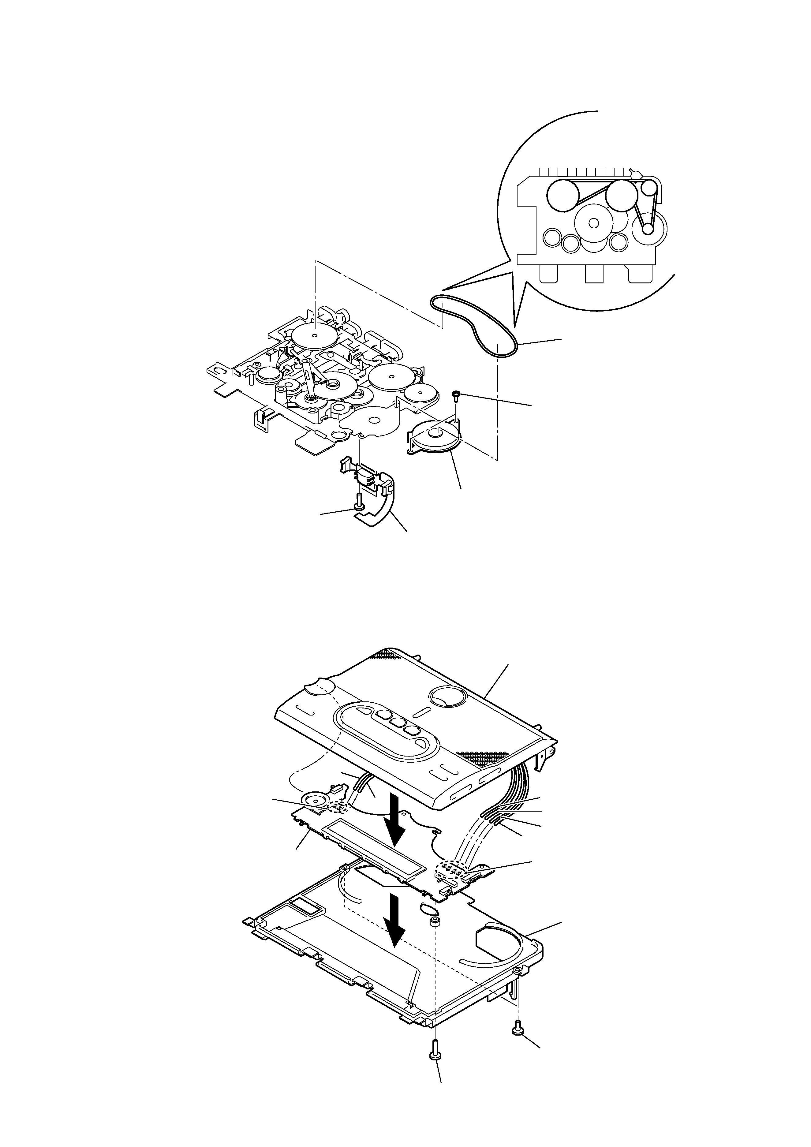
2-1. CABINET (FRONT), CABINET (REAR), "LID, CASSETTE ASSY"
Cabinet (Rear)
Cabinet (Front)
Main board
Mechanism deck
HRPE301 (REC/PB/ERASE head),
M601 (CAPSTAN/REEL motor), Belt (AR)
Set
Lid, cassette ASSY
Display board
Note on installing the
cassette lid assy
When installing the cassette lid ASSY,
insert the one side of the spring (toggle)
and set the other side into the gap on the
cabinet (front) as shown in the figure.
7
3
6
Remove from projection
6
Remove from projection
1
Screws (+B1.7X9)
2
Claws
5
Flexible board (22 core) (CN302)
4
Flexible board (22 core) (CN301)
Lid, cassette ASSY
Cabinet (front)
Cabinet (rear)
Hand strap
Spring (toggle)
4
WM-GX400
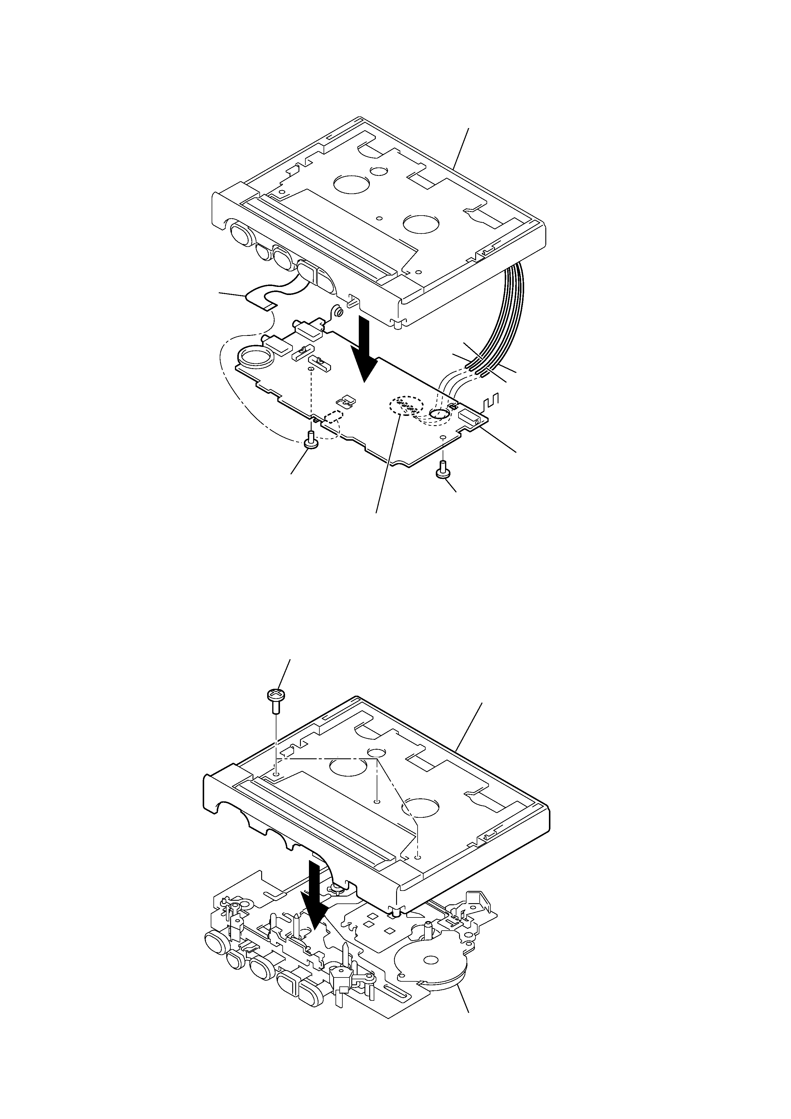
2-2. MAIN BOARD
2-3. MECHANISM DECK
4
Cabinet (front)
Black
Orange
Red
White
3
Screw (M1.4)
3
Screw (M1.4)
2
Flexible board (9 core)
(CN303)
1
Remove soldering
(four places)
Main board
2
1
Screws (IB LOCK)
Cabinet (front)
Mechanism deck (MT-WMGX400-175)
5
WM-GX400
5
3
Lid, cassette ASSY
Gray
Display board
White
Brown
Orange
Red
Black
Holder, cassette
4
Remove soldering (from SP101, SP201)
(four places)
4
Remove soldering (from MIC301)
(two places)
2
Screws (+BTP1.7)
1
Screw (+BTP1.7X5)
2-5. DISPLAY BOARD
2-4. HRPE301 (REC/PB/ERASE HEAD),
M601 (CAPSTAN/REEL MOTOR), BELT (AR)
Attaching belt (AR)
3
Belt (AR)
4
Screws (M1.4)
1
Screws (M1.4)
5
M601 (CAPSTAN/REEL motor)
2
HRPE301 (REC/PB/ERASE head)