WM-FX700/FX890/FX900
US Model
WM-FX890
E Model
Chinese Model
WM-FX700/FX890/FX900
Tourist Model
WM-FX890
SERVICE MANUAL
Ver. 1.2 2005. 09
RADIO CASSETTE-CORDER
Model Name Using Similar Mechanism
NEW
Tape Transport Mechanism Type
MF-WMFX890-162
SPECIFICATIONS
Sony Corporation
Personal Audio Group
Published by Sony Engineering Corporation
9-961-230-03
2005I02-1
© 2005.09
Photo: WM-FX700
Radio section
Frequency range
FM;
87.5 - 108 MHz
AM;
531 - 1602 kHz
Tape section
Frequency response
Playback;
40 - 15000Hz
Output
Headphones (i) jack
Load impedance 8 - 300
General
Power requirements
1.5V
Rechargeable battery
One R6 (size AA) battery
Dimensions (w/h/d)
Approx.77.1 x 108.0 x 22.5 mm
(31/8 x 43/3 x 29/32 inches) excl. projecting
parts and controls
Mass
Approx.153g (5.4 oz) (main unit only)
Supplied accessories
AC power adaptor (1)
Battery case (1)
Stereo headphones or earphones with remote control (1)
Charging stand (1)
Rechargeable battery (NH-14WM (A), 1.2V, 1350 mAh (min),
Ni-MH) (1)
Rechargable battery carrying case (1)
Carrying pouch (1)
Design and specifications are subject to change without notice.
WM-FX700/FX890/FX900
2
1. SERVICE NOTE ······························································· 3
2. GENERAL ·········································································· 5
3. DISASSEMBLY
3-1. "Case Block Assy" ·························································· 6
3-2. Main Board ····································································· 7
3-3. Belt ·················································································· 7
3-4. Motor (M601) ································································· 8
3-5. "Lid Assy, Cassette" ······················································· 8
3-6. "Ornament Block Assy, Reel" ········································ 9
3-7. "Holder (F) Assy ····························································· 9
3-8. "Pinch Lever (N)/(R) Assy ··········································· 10
3-9. Magnetic Head (HP901) ··············································· 10
4. MECHANICAL ADJUSTMENT ································ 11
5. ELECTRICAL ADJUSTMENT ·································· 11
6. DIAGRAMS ······································································ 14
6-1. Block Diagram ······························································ 15
6-2. Printed Wiring Board Main Section (Side A) ········· 16
Printed Wiring Board Main Section (Side B) ········· 17
6-3. Schematic Diagram Main Section (1/3) ·················· 18
6-4. Schematic Diagram Main Section (2/3) ·················· 19
6-5. Schematic Diagram Main Section (3/3) ·················· 20
6-6. IC Block Diagrams ······················································· 21
6-7. IC Pin Function Discription ·········································· 23
7. EXPLODED VIEWS
7-1. Case Section ·································································· 25
7-2. Mechanism Deck (MF-WMFX890-162) ······················ 26
8. ELECTRICAL PARTS LIST ······································· 27
r
UNLEADED SOLDER
Boards requiring use of unleaded solder are printed with the lead-
free mark (LF) indicating the solder contains no lead.
(Caution: Some printed circuit boards may not come printed with
the lead free mark due to their particular size.)
: LEAD FREE MARK
Unleaded solder has the following characteristics.
· Unleaded solder melts at a temperature about 40
°C higher than
ordinary solder.
Ordinary soldering irons can be used but the iron tip has to be
applied to the solder joint for a slightly longer time.
Soldering irons using a temperature regulator should be set to
about 350
°C.
Caution: The printed pattern (copper foil) may peel away if
the heated tip is applied for too long, so be careful!
· Strong viscosity
Unleaded solder is more viscous (sticky, less prone to flow)
than ordinary solder so use caution not to let solder bridges
occur such as on IC pins, etc.
· Usable with ordinary solder
It is best to use only unleaded solder but unleaded solder may
also be added to ordinary solder.
Notes on chip component replacement
· Never reuse a disconnected chip component.
· Notice that the minus side of a tantalum capacitor may be
damaged by heat.
Flexible Circuit Board Repairing
· Keep the temperature of soldering iron around 270°C
during repairing.
· Do not touch the soldering iron on the same conductor of the
circuit board (within 3 times).
· Be careful not to apply force on the conductor when soldering
or unsoldering.
SAFETY-RELATED COMPONENT WARNING!!
COMPONENTS IDENTIFIED BY MARK 0 OR DOTTED LINE WITH
MARK 0 ON THE SCHEMATIC DIAGRAMS AND IN THE PARTS
LIST ARE CRITICAL TO SAFE OPERATION. REPLACE THESE
COMPONENTS WITH SONY PARTS WHOSE PART NUMBERS
APPEAR AS SHOWN IN THIS MANUAL OR IN SUPPLEMENTS
PUBLISHED BY SONY.
TABLE OF CONTENTS
WM-FX700/FX890/FX900
3
3. FF, REW modes
(1) Check that the preset state is set.
(2) Input the square wave or sine wave to the TP36 (P. IN) and the
BATT # terminal.
(3) Press the x button (S703) to set the STOP mode.
(4) Press the FF AMS
button (S708) or the REW AMS
button(S707).
4. PLAY mode
(1) Check that the preset state is set.
(2) Input the square wave or sine wave to the TP36 (P. IN) and the
BATT # terminal.
(3) Press the x button (S703) to set the STOP mode.
(4) Press the n N REPEAT button (S709) will move the slider
(NR) once towards the side R and then to the side F.
Move the DIRECTION switch (S801) according to this timing
will set the PLAY mode (side F). Press the n N REPEAT
button (S709) another time and move the DIRECTION switch
(S801) according to the movement of the slider (NR) will set
the PLAY (R mode).
Note 1: If the above fails, perform from preset again.
Note 2: Use the nN REPEAT (S709), x (S703), FF AMS
(S708), and REW AMS (S707) buttons on the remote
controller as much as possible. If no remote controller, do
not touch the buttons with your hands, but using a stick
with a round tip.
Note 3: When using headphones, the timing for move the
DIRECTION switch (S801) can be determined from the
beep sound.
SECTION 1
SERVICE NOTE
This set detects the rotation of the idler gear (A) (side S) using the
PH701 (photo reflector). The PH701 is mounted on the MAIN
board, therefore the idler gear (A) (side S) cannot be detected with
the MAIN board removed. As a result, the motor (M601) cannot
be controlled, causing malfunction.
Further, the DIRECTION switch (S801) is also mounted on the
MAIN board, and with the board removed, the mechanism position
cannot be detected and the operation is not changed over.
Therefor, when the voltage check is executed with the MAIN board
removed, follow the procedure provided below.
1. Setting
(1) Refer to "3. DISASSEMBLY", and remove the MAIN board.
(2) Connect the MAIN board to the motor (M601) and the plunger
(PM901) using jumper wires. These can be connected easily
with the use of the extension tool (Part No. 1-769-143-11) (ten
in one set).
(3) Short the TAPE DETECT switch (S501-1) terminals and the
ATS switch (S501-2) terminals.
(4) Connect the AF oscillator to the TP36 (P. IN) and the BATT#
terminal.
(5) Supply 1.3 V to the battery terminals using the regulated power
supply.
2. Preset state
To set the PLAY, FF, REW modes, the preset state must be set.
(1) Check that the slider (NR) and the DIRECTION switch (S801)
are set to the center position. If not, set the preset state as follow.
(2) Move the DIRECTION switch (S801) to the side, which the
slider (NR) is facing.
(3) The slider (NR) will move when the regulated power supply
switch is set to OFF once and then set to ON. Move the
DIRECTION switch (S801) according to this timing and set to
the center position.
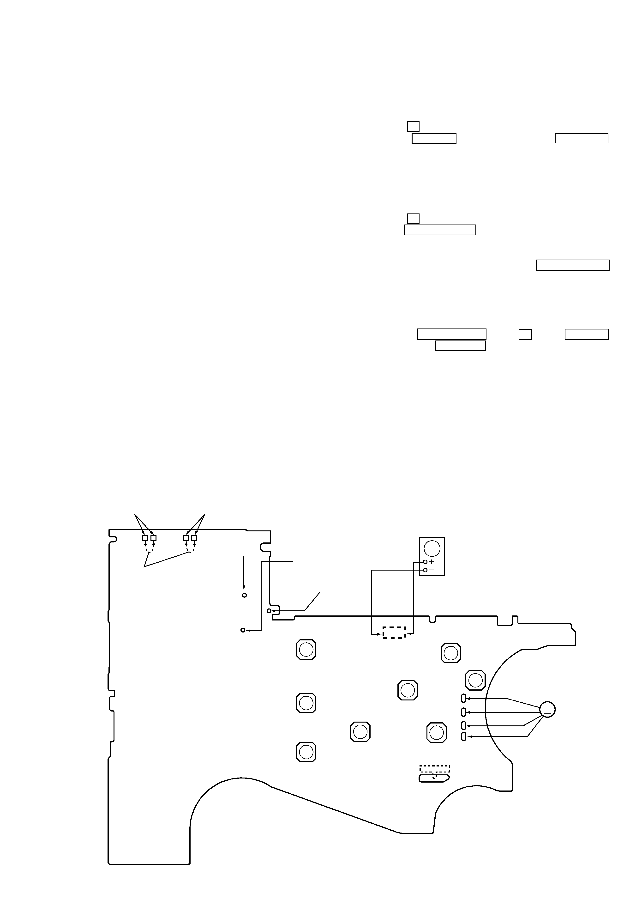
MAIN BOARD (SIDE B) --
ENTER
(S702)
RADIO ON/
BAND
(S704)
MENU
(S706)
R710
(Side A)
SET
(S705)
(S801)
FWDSTOPREV
Battery terminal #
Sine wave
10 Hz, -3.5 dB
OSC
Plunger (PM901)
Short
ATS SWITCH
(S501-2)
TAPE DETECT
SWITCH
(S501-1)
Y
REPEAT
(S709)
FF/PRESET+
(S708)
REW/PRESET
(S707)
x
RADIO OFF
(S703)
M601
M
WM-FX700/FX890/FX900
4
Slider (NR)
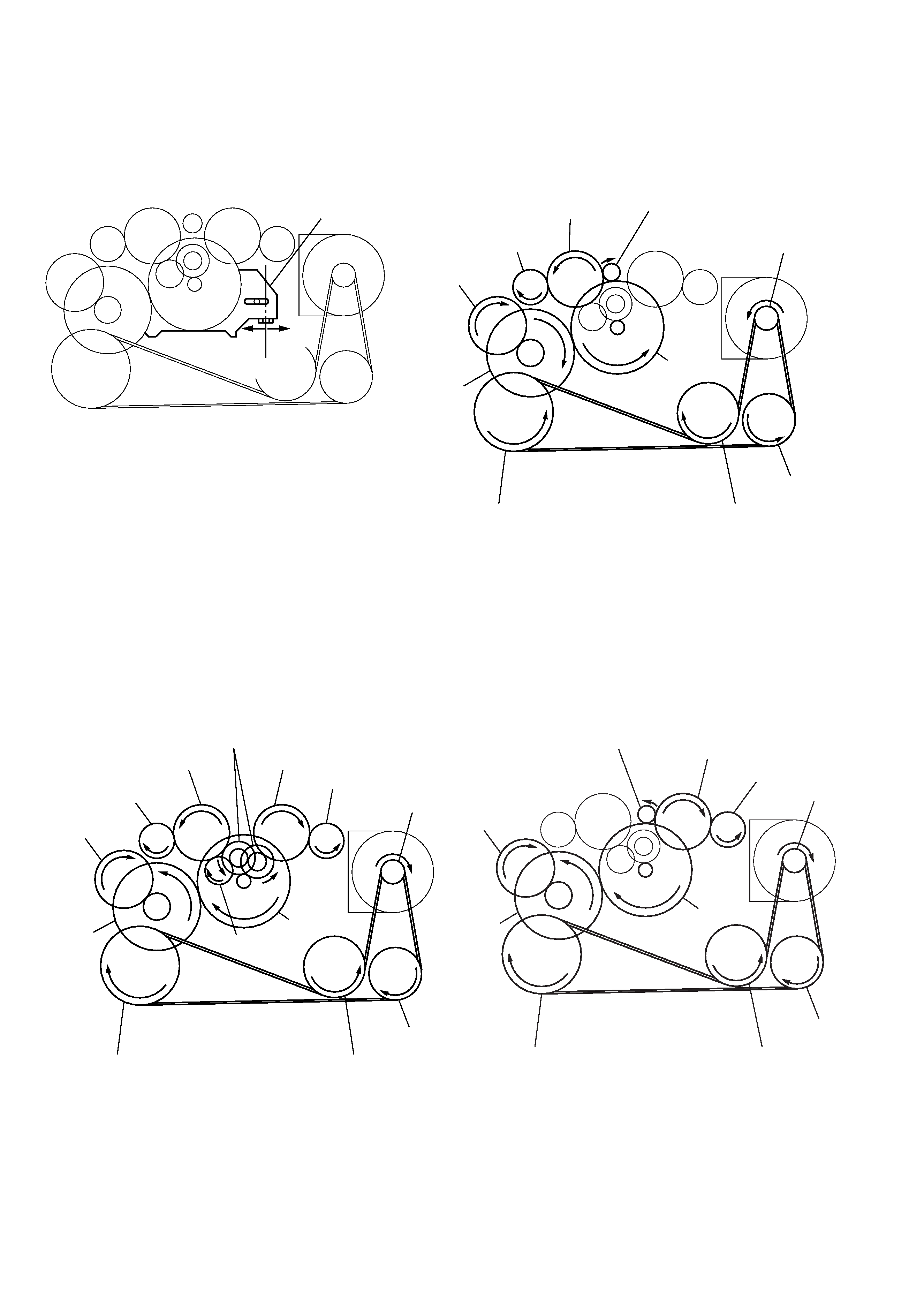
Tape drive mechanism
Tape drive mechanism in PLAY mode
Tape drive mechanism in FF mode
Tape drive mechanism in REW mode
slider (NR )
side F side R
center
ins ert flywheel (N)
ins ert flywheel (R)
reverse pulley
clutch as s y(F)
gear (Y)
cam gear
gear (REEL) (side T )
motor pulley
idler gear (A) (side T )
gear (FR )
(FF:left s ide)
ins ert flywheel (N)
ins ert flywheel (R)
reverse pulley
clutch as s y(F)
idler gear (B)
gear (Y)
cam gear
gear (REEL) (side T )
gear (REEL) (side S )
motor pulley
idler gear (A) (side T )
idler gear (A) (side S )
gear (NR )
(FW D : left s ide/
REV : right s ide)
ins ert flywheel (N)
ins ert flywheel (R)
reverse pulley
clutch as s y(F)
gear (Y)
cam gear
gear (REEL)
(side S )
motor pulley
idler gear (A)
(side S )
gear (FR )
(RE W: right s ide)
WM-FX700/FX890/FX900
5
SECTION 2
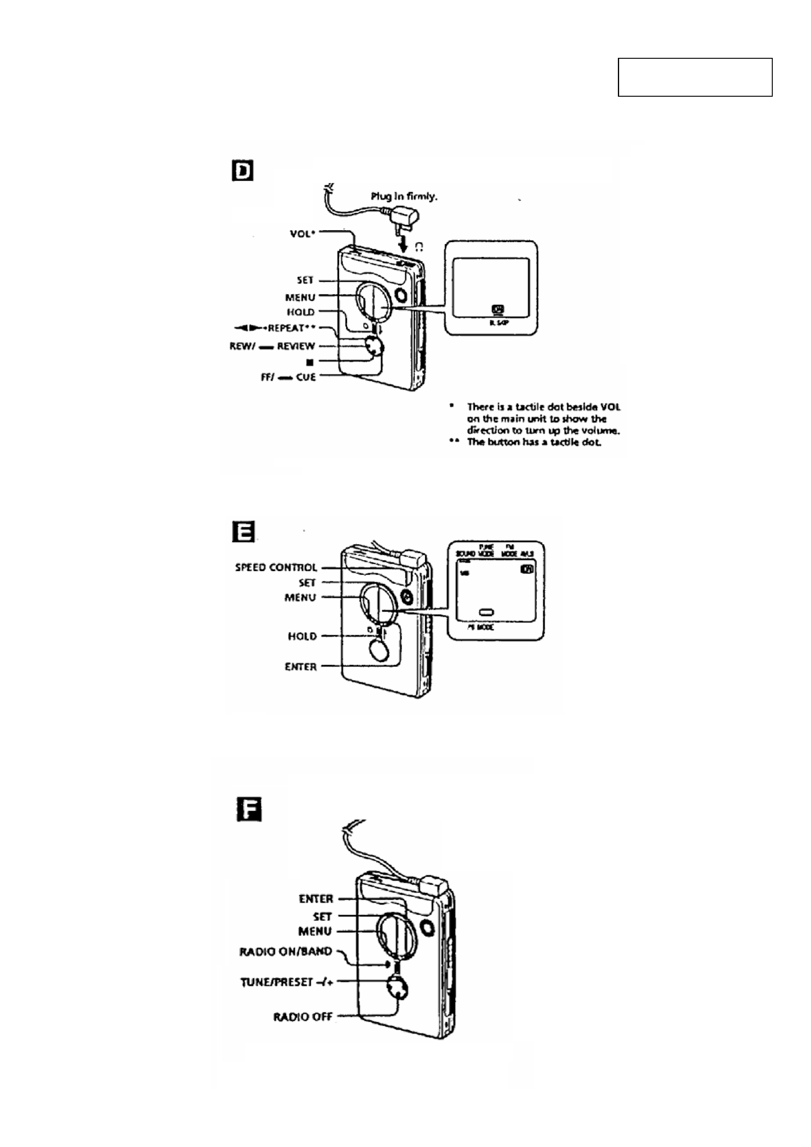
GENERAL
· LOCATION OF CONTROLS
This section is extracted
from instruction manual.