SERVICE MANUAL
Ver 1.1 2002.06
9-873-396-02
Sony Corporation
2002F0500-1
Personal Audio Company
C
2002.06
Published by Sony Engineering Corporation
RADIO CASSETTE PLAYER
E Model
Chinese Model
Tourist Model
SPECIFICATIONS
WM-FX888
Manufactured under license from Dolby Laborato-
ries.
"Dolby" and the double-D symbol are trademarks of
Dolby Laboratories.
Model Name Using Similar Mechanism
WM-FX675
Tape Transport Mechanism Type
MF-WMFX671-162
Radio section
Frequency range
FM: 87.5 - 108 MHz
AM: 530 - 1 710 kHz (North, Central, and South America)
531 - 1 602 kHz (other countries)
Tape section
Frequency response (Dolby NR off)
Playback: 40 - 15 000 Hz
Output
Headphones (i) jack
Load impedance 8 - 300
General
Power requirements
1.5 V
Rechargeable battery
One R6 (size AA) battery
Dimensions (w/h/d)
Approx. 108.4
× 77.7 × 23.0 mm
(43/
8 × 3
1/
8 ×
29/
32 inches)
Mass
Approx. 160 g (5.7 oz)
Supplied accessories
· AC power adaptor (1)
· Battery case (1)
· Stereo headphones or earphones with remote control (1)
· Charging stand (1)
· Rechargeable battery (NC-6WM, 1.2 V, 600 mAh, Ni-Cd) (1)
· Rechargeable battery carrying case (1)
· Carrying pouch (1)
Design and specifications are subject to change without notice.
Battery life (Approx. hours)
(JEITA*)
Sony alkaline LR6 (SG)**
Tape playback
36
Radio reception
32
Rechargeable battery (NC-6WM)
Tape playback
10
Radio reception
10
Sony alkaline LR6 (SG)** and
Rechargeable NC-6WM
Tape playback
45
Radio reception
42
* Measured value by the standard of JEITA (Japan
Electronics and Information Technology Industries
Association). (Using a Sony HF series cassette tape)
**When using a Sony LR6 (SG) "STAMINA" alkaline dry
battery (produced in Japan).
Note
· The battery life may be shorter depending on the
operating condition, the surrounding temperature and
battery type.

2
WM-FX888
Note on the AC power adaptor
Use only the supplied AC power adaptor. Do not use
any other AC power adaptor.
Polarity of
the plug
TABLE OF CONTENTS
1.
SERVICING NOTES ............................................... 3
2.
GENERAL ................................................................... 5
3.
DISASSEMBLY
3-1. Disassembly Flow ...........................................................
6
3-2. Case Section ....................................................................
6
3-3. MAIN Board ...................................................................
7
3-4. Belt (F2) ..........................................................................
7
3-5. Motor (Capstan/Reel) (M601) ........................................
8
3-6. Cassette Lid Sub Assy .....................................................
8
3-7. Reel Ornament Block Assy .............................................
9
3-8. Holder (F) Assy (/M) ......................................................
9
3-9. Pinch Lever (RA)/(NA) Assy ......................................... 10
3-10. Magnetic Head (Playback) (HP901) .............................. 10
4.
MECHANICAL ADJUSTMENTS ....................... 11
5.
ELECTRICAL ADJUSTMENTS ......................... 11
6.
DIAGRAMS
6-1. Block Diagram TUNER Section ............................. 13
6-2. Block Diagram MAIN Section ................................ 14
6-3. Note for Printed Wiring Board
and Schematic Diagrams ................................................ 15
6-4. Printed Wiring Board MAIN Board (Side A) ......... 16
6-5. Printed Wiring Board MAIN Board (Side B) ......... 17
6-6. Schematic Diagram MAIN Board (1/2) .................. 18
6-7. Schematic Diagram MAIN Board (2/2) .................. 19
6-8. IC Pin Function Description ........................................... 21
7.
EXPLODED VIEWS
7-1. Case Section .................................................................... 23
7-2. Chassis Section ............................................................... 24
7-3. Main Section ................................................................... 25
7-4. Mechanism Deck Section-1 (MF-WMFX671-162) ....... 26
7-5. Mechanism Deck Section-2 (MF-WMFX671-162) ....... 27
7-6. Mechanism Deck Section-3 (MF-WMFX671-162) ....... 28
8.
ELECTRICAL PARTS LIST ............................... 29
Notes on chip component replacement
· Never reuse a disconnected chip component.
· Notice that the minus side of a tantalum capacitor may be dam-
aged by heat.
Flexible Circuit Board Repairing
· Keep the temperature of the soldering iron around 270 °C dur-
ing repairing.
· Do not touch the soldering iron on the same conductor of the
circuit board (within 3 times).
· Be careful not to apply force on the conductor when soldering
or unsoldering.
SAFETY-RELATED COMPONENT WARNING!!
COMPONENTS IDENTIFIED BY MARK 0 OR DOTTED
LINE WITH MARK 0 ON THE SCHEMATIC DIAGRAMS
AND IN THE PARTS LIST ARE CRITICAL TO SAFE
OPERATION. REPLACE THESE COMPONENTS WITH
SONY PARTS WHOSE PART NUMBERS APPEAR AS
SHOWN IN THIS MANUAL OR IN SUPPLEMENTS PUB-
LISHED BY SONY.
3
WM-FX888
SECTION 1
SERVICING NOTES
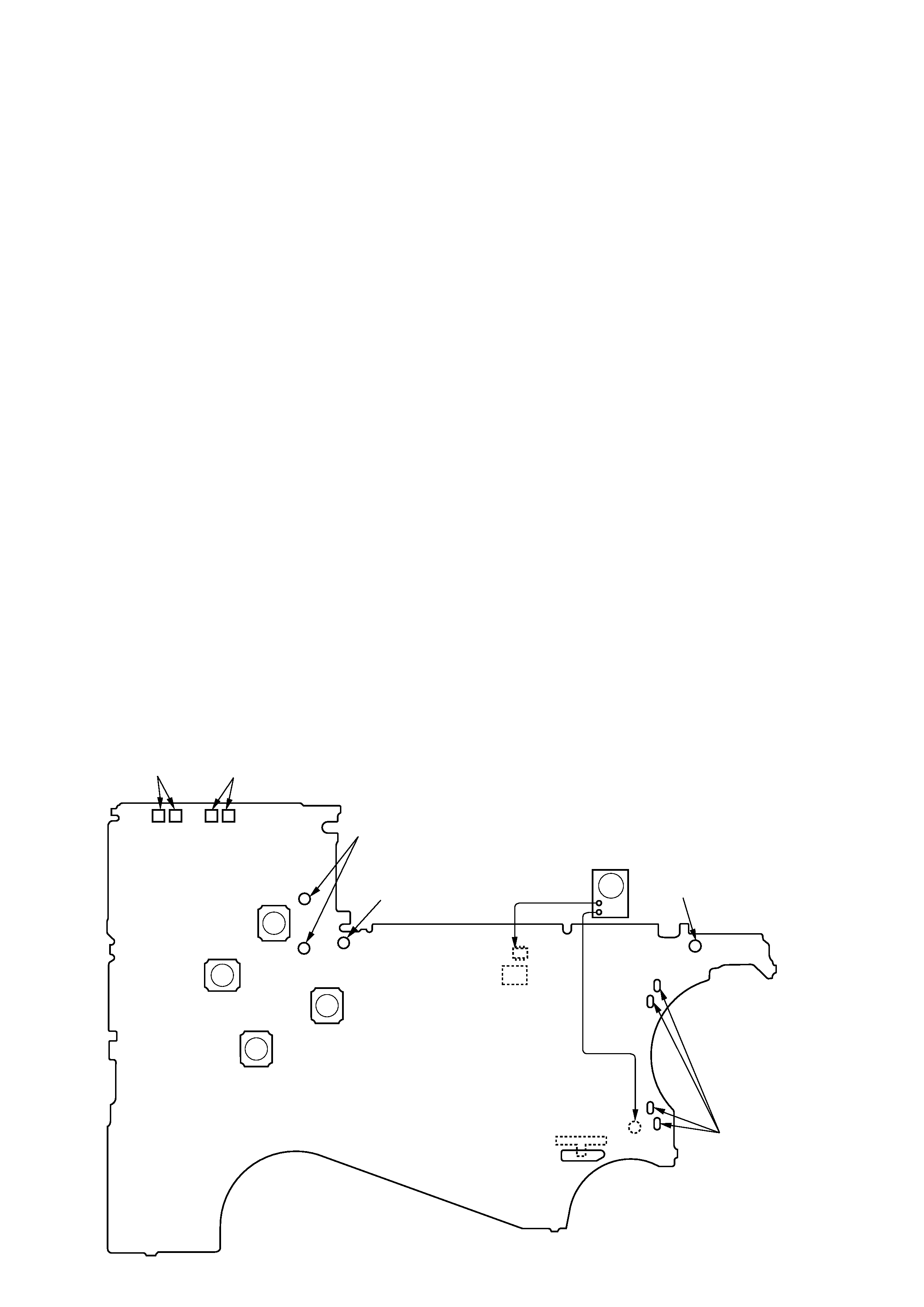
This set detects the rotation of the idler gear (A) (side S) using the
PH1 (photo reflector). The PH1 is mounted on the MAIN board,
therefore the idler gear (A) (side S) cannot be detected with the
MAIN board removed. As a result, the motor (M601) cannot be
controlled, causing malfunction.
Further, the DIRECTION switch (S1) is also mounted on the MAIN
board, and with the board removed, the mechanism position can-
not be detected and the operation is not changed over.
Therefor, when the voltage check is executed with the MAIN board
removed, follow the procedure provided below.
1. Setting
(1)
Refer to "3. DISASSEMBLY", and remove the MAIN board.
(2)
Connect the MAIN board to the motor (M601) and the
plunger (PM901) using jumper wires. These can be connected
easily with the use of the extension tool (Part No. 1-769-
143-11) (ten in one set).
(3)
Short the TAPE DETECT switch (S901-1) terminals and the
ATS switch (S901-2) terminals.
(4)
Connect the AF oscillator to the Q15-1 (COLLECTOR) and
the TP23 (GND).
(5)
Supply 1.3 V to the battery terminals using the regulated
power supply.
2. Preset state
To set the PLAY, FF, REW modes, the preset state must be set.
(1)
Check that the slider (NR) and the DIRECTION switch (S1)
are set to the center position. If not, set the preset state as
follow.
(2)
Move the DIRECTION switch (S1) to the side, which the
slider (NR) is facing.
(3)
The slider (NR) will move when the regulated power supply
switch is set to OFF once and then set to ON. Move the DI-
RECTION switch (S1) according to this timing and set to
the center position.
3.
FF, REW modes
(1)
Check that the preset state is set.
(2)
Input the square wave or sine wave to the Q15-1 (COLLEC-
TOR) and the TP23 (GND).
(3)
Press the [ RADIO OFF] button (S3) to set the STOP mode.
(4)
Press the [+ FF] button (S4) or the [-- REW] button (S5).
4. PLAY mode
(1)
Check that the preset state is set.
(2)
Input the square wave or sine wave to the Q15-1(COLLEC-
TOR) and the TP23 (GND).
(3)
Press the [
RADIO OFF] button (S3) to set the STOP mode.
(4)
Press the [
REPEAT] button (S9) will move the slider
(NR) once towards the side R and then to the side F. Move
the DIRECTION switch (S1) according to this timing will
set the PLAY mode (side F). Press the [
REPEAT] button
(S9) another time and move the DIRECTION switch (S1)
according to the movement of the slider (NR) will set the
PLAY (R mode).
Note 1: If the above fails, perform from preset again.
Note 2: Use the [
REPEAT] (S9)
, [ RADIO OFF] (S3), [+ FF] (S4),
and [-- REW] (S5) buttons on the remote controller as much as
possible. If no remote controller, do not touch the buttons with
your hands, but using a stick with a round tip.
Note 3: When using headphones, the timing for move the DIRECTION
switch (S1) can be determined from the beep sound.
+
+ FF
(S4)
connect to the plunger
(PM901)
battery
terminal #
battery
terminal 3
square wave
(sine wave)
10 Hz, 3.5 dB
AF oscillator
TAPE DETECT
(S901-1)
MAIN Board (side B)
ATS
(S901-2)
REW
(S5)
TP23
(GND)
S1
DIRECTION
FWDTSTOPtREV
Y
REPEAT
(S9)
x
RADIO OFF
(S3)
PH1
Q15
connect to the
motor (M601)
x
x
Y
Y
Yx
4
WM-FX888
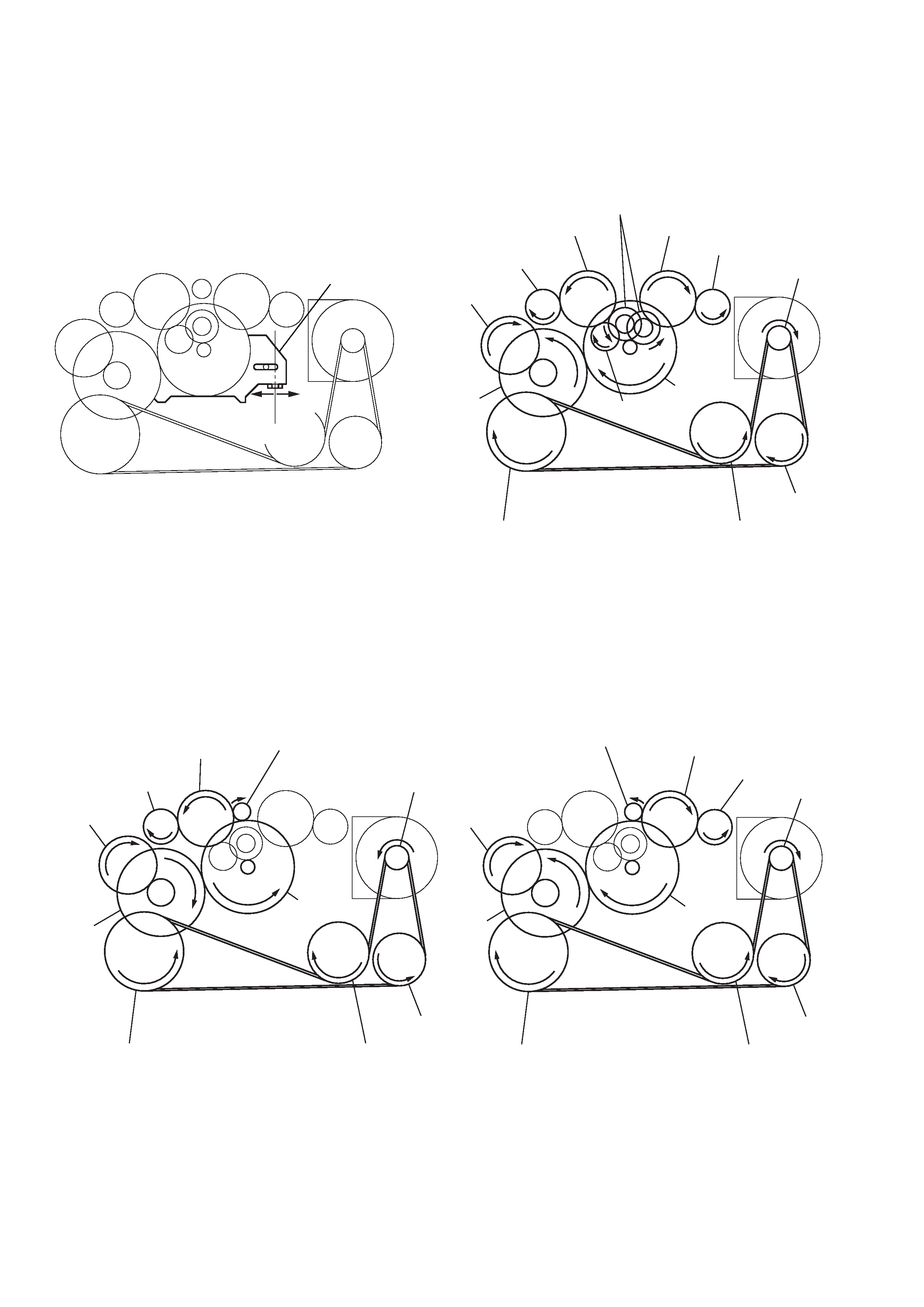
Slider (NR)
Rotation system
Rotation system during PLAY.
Rotation system during FF.
Rotation system during REW.
slider (NR)
side F side R
center
insert flywheel (N)
insert flywheel (R)
reverse pulley
clutch assy (F)
gear (Y)
cam gear
gear (REEL) (side T)
motor pulley
idler gear (A) (side T)
gear (FR)
(FF: left side)
insert flywheel (N)
insert flywheel (R)
reverse pulley
clutch assy (F)
idler gear (B)
gear (Y)
cam gear
gear (REEL) (side T)
gear (REEL) (side S)
motor pulley
idler gear (A) (side T)
idler gear (A) (side S)
gear (NR)
(FWD : left side/
REV : right side)
insert flywheel (N)
insert flywheel (R)
reverse pulley
clutch assy (F)
gear (Y)
cam gear
gear (REEL)
(side S)
motor pulley
idler gear (A)
(side S)
gear (FR)
(REW: right side)
5
WM-FX888
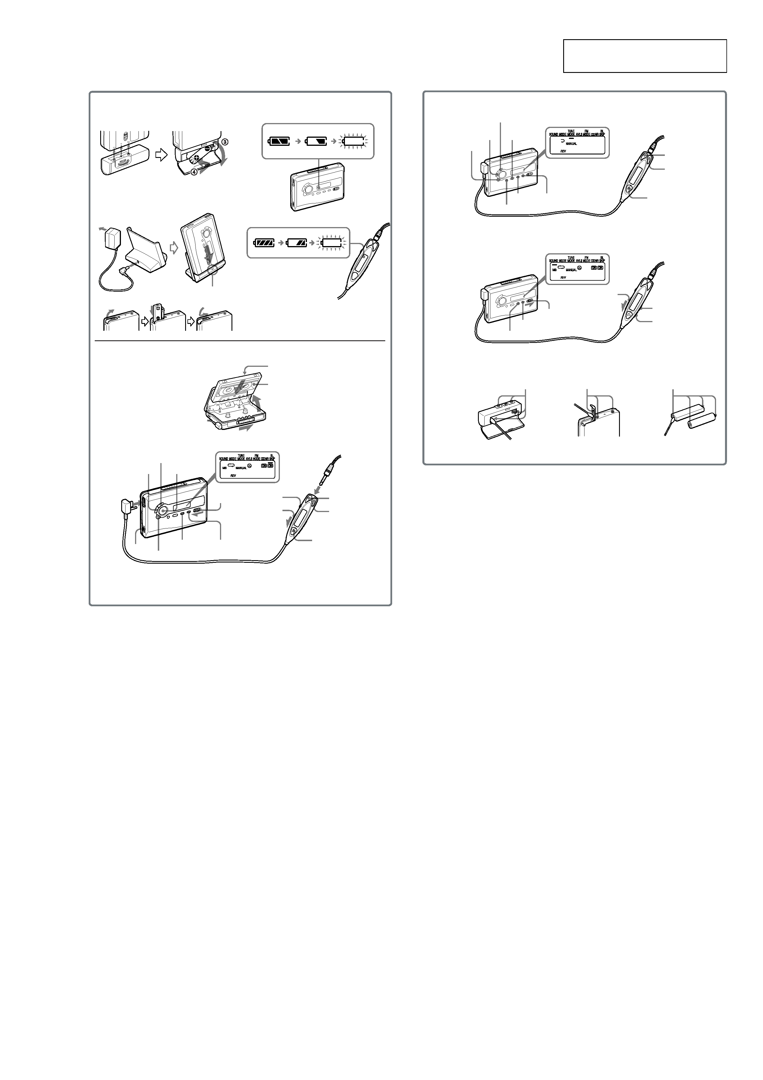
F
E
G
RADIO OFF
SET
MENU
TUNE/PRESET +
RADIO ON/
BAND·OFF
+
TUNE/PRESET
ENTER
SET
MENU
HOLD
HOLD
BAND·
RADIO ON
Terminals
Terminals
Terminals
SOUND
MODE
B
C
D
x
VOL*
VOL
HOLD
HOLD
Y
·REPEAT**
FF (AMS)
REW (AMS)
Y
·x**
REW
Plug in firmly.
i
FF
MENU
SET
A
CHARGE
FWD (forward) side
REV (reverse) side
* There is a tactile dot beside VOL on the main unit to show the direction to turn up the volume.
** The button has a tactile dot.
SECTION 2
GENERAL
This section is extracted from
instruction manual.