WM-FX491/FX491ST/FX493/FX493ST
RADIO CASSETTE PLAYER
SPECIFICATIONS
US Model
WM-FX493/FX493ST
Canadian Model
WM-FX491/FX491ST/FX493ST
AEP Model
E Model
Chinese Model
WM-FX491/FX493
Model Name Using Similar Mechanism
WM-FX477
Tape Transport Mechanism Type
MT-WMEX404-147
Photo : WM-FX493
SERVICE MANUAL
· Frequency range
FM: 87.5108 MHz
AM: 5301710 kHz (US, Canadian, 5E, 6E model)
5311602 kHz (EXCEPT US, Canadian, 5E, 6E model)
· Power requirements
3 V DC batteries R6 (size AA) x 2
· Dimensions (w/h/d)
Approx. 115.8 x 83.2 x 30.1 mm, incl. projecting parts and
controls
· Mass
Approx. 115 g/Approx. 195 g (incl. a battery and a cassette)
· Supplied accessories
Stereo headphones or earphones with remote control (1)
(FX493/FX493ST)/Stereo headphones or earphones (1)
(FX491/FX491ST)
Design and specifications are subject to change without
notice.
· Abbreviation
5E, 6E : South America
Battery life (approximate hours)
(EIAJ*)
Sony alkaline LR6 (SG)
Sony R6P (SR)
Tape playback
25
7.5
Radio reception
40
14
* Measured value by the standard of EIAJ (Electronic
Industries Association of Japan). (Using a Sony HF series
cassette tape)
Note
· The battery life may shorten depending on the operation of
the unit.
9-927-641-13
2001H0200-1
© 2001.8
Sony Corporation
Parsonal Audio Company
Shinagawa Tec Service Manual Production Group
Ver 1.2 2001.08
About new "WM" logo model of
WM-FX491(AEP, Canadian), refer
to other service manual (9-873-275-01).
2
Specifications ........................................................................... 1
1. GENERAL
Location and Function of Controls .................................... 3
2. DISASSEMBLY
2-1. Cabinet (Front) Sub ASSY ......................................... 5
2-2. Main Board ................................................................. 5
2-3. Mechanism Deck ........................................................ 6
2-4. Belt, Motor (Capstan/Reel) (M901) ........................... 6
2-5. "Holder Sub ASSY, Cassette" .................................... 7
3. ADJUSTMENTS
3-1. Mechanical Adjustments ............................................. 8
3-2. Electrical Adjustments ................................................ 8
4. DIAGRAMS
4-1. Explanation of IC Terminals ...................................... 11
4-2. Block Diagram .......................................................... 13
4-3. Printed Wiring Boards .............................................. 15
4-4. Schematic Diagram ................................................... 19
5. EXPLODED VIEWS
5-1. Cabinet Section ......................................................... 23
5-2. Mechanism Deck Section (MT-WMEX404-147) .... 24
6. ELECTRICAL PARTS LIST ................................... 25
Flexible Circuit Board Repairing
· Keep the temperature of the soldering iron around 270
°C during
repairing.
· Do not touch the soldering iron on the same conductor of the
circuit board (within 3 times).
· Be careful not to apply force on the conductor when soldering or
unsoldering.
Notes on chip component replacement
· Never reuse a disconnected chip component.
· Notice that the minus side of a tantalum capacitor may be dam-
aged by heat.
TABLE OF CONTENTS
SERVICING NOTES
Writing EEPROM
When IC703 (EEPROM) is replaced, write the destination for
the set into the EEPROM with the following method.
1. Use a wire to short TP708 to ground.
2. Press the key below that matches the destination or short the
printed pattern section with tweezers or the like.
STOP key: US, Canadian
PLAY key: E, 5E, 6E, 9E
FF key: AEP, French, CEV, Saudi Arabia, Chinese
3. The moment the key is pressed, the destination is written
into the EEPROM from the microprocessor. (It is also
possible to rewrite after writing.)
4. Remove the shorting wire connected in 1.
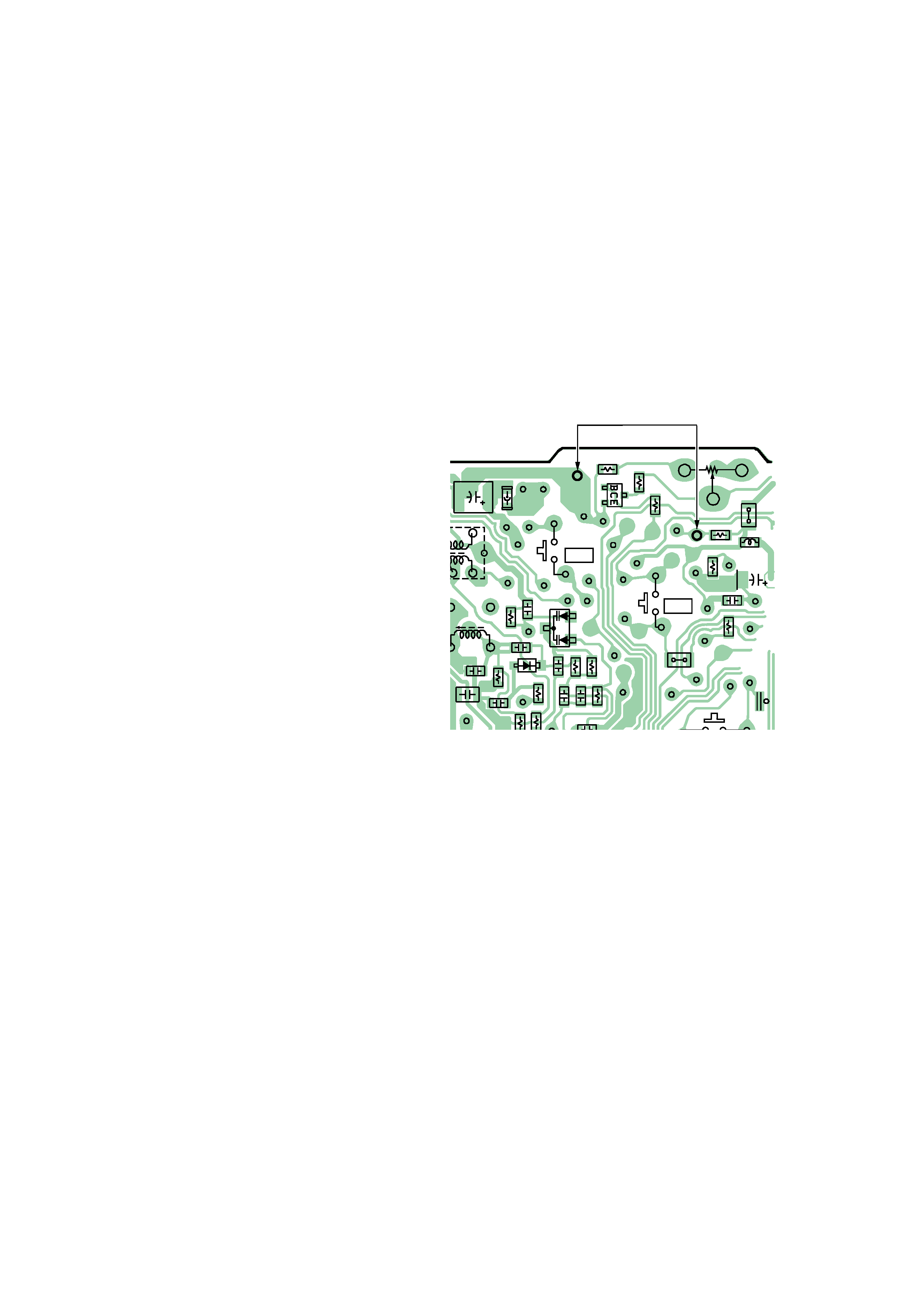
R609
R3
R4
R6
R8
R10
R5
C10
C11
C4
C13
C31
S707
FF +
C12
C6
C7
S714
R608
R606
R7
TP129
RV601
TP770
TP21
TP740
C702
Q603
C30
L701
D3
D2
R708
C14
TP708
R702
R703
TP745
FB2
C41
TP735
JC109
JC110
TP734
TP725
TP764
(GND)
TP809
L4
L3
4
TP204
w
Y
[MAIN BOARD]
(Side B)
Ver 1.1 2001.07
3
SECTION 1
GENERAL
LOCATION AND FUNCTION OF CONTROLS
This section is extracted from
instruction manual.
A
HOLDB
TUNING
BAND
RADIO ON
PRESET
REW
x
Y
FF
PRESET
RADIO OFF
MB MODE TAPE AVLS
FM MODE
B
FWD
REV
OPEN
MENU
SET
ENTER
Plug in firmly.
Branchez fermement.
FX493
FX491
VOL
FF/PRESET+
TUNING+/
x/RADIO OFF
REW/PRESET
RADIO ON /BAND
VOL
Y
Y·x (RADIO
ON/BAND·OFF)
HOLD
FF/PRESET+
C
FX493
FX491
MENU
MENU
SET
SET
FX493
REW/PRESET

4
Listening to the Radio B
1
If the HOLD function is turned on, slide the
HOLD switch in the opposite direction of
the arrow to unlock the controls.
2
Press RADIO ON/BAND to turn on the
radio.
3
Press RADIO ON/BAND repeatedly to
select AM, FM1, FM2 or FM3.
4
Press TUNING +/ to tune in to the desired
station.
If you keep pressing TUNING+/ for
a few seconds, the Walkman will start
tuning to the stations automatically.
To turn off the radio
Press x·RADIO OFF.
To improve the broadcast reception C
· For FM:
Extend the headphones/earphones cord
(antenna) (FX491) or remote control cord (antenna)
(FX493). If the reception is still not good, press
MENU repeatedly to set the cursor to FM MODE in
the display.
· For AM:
Reorient the unit itself.
Presetting Radio Stations
You can store radio stations into the unit's memory.
You can preset up to 32 radio stations, 8 for each
FM1, FM2, FM3 or AM bands.
1
Press RADIO ON/BAND to turn on the
radio.
2
Press RADIO ON/BAND repeatedly to
select AM, FM1, FM2 or FM3.
3
Press ENTER.
The frequency digits and a preset number
flash in the display.
4
While the frequency digits and the preset
number are flashing, tune in to a station you
wish to store using TUNING+/, and select
a preset number using PRESET+/.
5
While the frequency digits and the preset
number are flashing, press ENTER.
Notes
· If you cannot complete step 4 or 5 while the indications
are flashing, repeat from step 3.
· If a station is already stored, the new station replaces
the old one.
To cancel the stored station
Follow the procedure above and in step 3, instead of
tuning in to a station, press and hold TUNING +/ until
"- - - -" is displayed. Press ENTER while "- - - -" is
flashing.
To play the preset radio stations
1
Press RADIO ON/BAND to select the band.
2
Press PRESET+/.
To operate from the remote control
(FX493 only)
To turn on the radio, press RADIO ON/BAND·OFF
for more than one second (only while the tape is in
stop mode).
To select the band, press RADIO ON/BAND·OFF
for more than one second while the radio is on.
To tune in or recall a preset station, press PRESET +
or .
To turn off the radio, press RADIO ON/BAND·OFF.
Using Other Functions
To lock the controls
Set the HOLD switch to the direction of the arrow to
lock the controls.
Preparations
To Insert Batteries A
1
Slide and open the battery compartment lid,
and insert two R6 (size AA) dry batteries
with correct polarity.
Replace the batteries with new ones when " e "
flashes in the display.
Playing a Tape B
1
If the HOLD function is turned on, slide the
HOLD switch in the opposite direction of
the arrow to unlock the controls.
2
Insert a cassette and press MENU
repeatedly to set the cursor to TAPE in the
display. Then press SET to select the tape
type.
No message: normal (TYPE I)
METAL: CrO2 (TYPE II) or metal (TYPE IV)
3
Press Y on the main unit, or if using the
remote control (FX493 only), press Y
(play)·x (stop).
Adjust the volume with VOL.
When adjusting the volume on the Walkman (FX493
only)
Set the VOL control on the remote control at maximum.
When adjusting the volume on the remote control
(FX493 only)
Set the VOL control on the Walkman slightly above the
appropriate level.
Note on the cassette holder
When opening the cassette holder, press the x (stop)
button and make sure the tape is stopped by checking
through the cassette window, then slide the OPEN
switch.
If the cassette holder is opened before the tape is
stopped, the tape may loosen and be damaged.
Operation on the main unit
To
Switch playback to
the other side
Stop playback
Operation on the remote control (FX493
only)
To
Switch playback to
the other side
Stop playback
Other tape operations
To
Fast forward*
Rewind*
Play the same side from
the beginning (Auto
Play function)
Play the other side from
the beginning (Skip
Reverse function)
* For FX493 only: If Y·x on the remote control is
pressed during fast forward or rewind, the Walkman
switches to playback.
To select playback mode
Press MENU repeatedly to set the cursor to MODE in
the display.
Then press SET to select the desired mode.
To play
Both sides repeatedly
Both sides once from
the side facing the
cassette holder
Press
Y·x for 2 seconds or
more during playback
Y·x once during
playback
Press
Y (play)during playback
x
Select
s
d
Press
FF during stop
REW during stop
REW during playback
FF during playback
To emphasize bass sound
Press MENU repeatedly to set the cursor to MB in the
display. Then, press SET to turn MB on. With each
press, the indications change as follows.
MB (MEGA BASS) : emphasizes bass sound
No message: off (normal)
Notes
· If the sound is distorted with the mode "MB", turn
down the volume of the main unit or select normal
mode.
· Bass emphasis may not show great effect if the volume
is turned up too high.
To protect your hearing--AVLS
(Automatic Volume Limiter System)
function
When you set the AVLS function to active, the
maximum volume is kept down to protect your ears.
Press MENU repeatedly to set the cursor to AVLS in
the display. Then press SET to show "
".
Note
· The AVLS setting will be canceled when you replace
the batteries.
5
SECTION 2
DISASSEMBLY
Note : Follow the disassembly procedure in the numerical order given.
2-1. CABINET (FRONT) SUB ASSY
2-2. MAIN BOARD
z
The equipment can be removed using the following procedure.
Main board
Cabinet (Front) sub ASSY
Holder sub ASSY, Cassette
Mechanism deck
Belt, Motor (Capstan/reel) (M901)
Set
Cabinet (Front) sub ASSY
4
Screws (B1.7x12)
Lid, Battery case
Center cabinet
2
OPEN
6
Claws
3
7
1
6
Claws
5
Claws
6
Claws
Main board
3
Screw
Black
Orange
White
Red
Switch (S601)
Head flexible board
5
2
1
Remove solder
Center cabinet
4
Claws