WM-FX451
SERVICE MANUAL
SPECIFICATIONS
US Model
AEP Model
E Model
Model Name Using Similar Machanism
WM-FX453
Tape Transport Mechanism Type
MF-WMFX453-114
Frequency range
FM :
87.5 108 MHz
AM :
530 1710kHz (US, 7E model)
531 1602kHz (EXCEPT US, 7E model)
Battery life (Aprrox. hours)
Sony alkaline LR6 (SG)
Sony R6P (SR)
playback
24
7.5
radio
33
13
Power requirements
3V DC batteries R6 (AA) x2/External DC 3V power sources
Dimensions
112.5x87.3x35.2 mm (4 1/
2 x 3
1/
2 x1
7/
16 inches) (w/h/d) incl.
projecting parts and controls
Mass
Approx. 155g (5.5 oz)
Approx. 235g (8.3 oz) incl. batteries, a cassette and headphones
Supplied accesories
Stereo headphones (1)/Belt clip (1)
Design and specifications are subject to change without notice
RADIO CASSETTE PLAYER
Ver 1.3 2004. 03
9-923-305-12
2004C02-1
© 2004.03
Sony Corporation
Personal Audio Company
Published by Sony Engineering Corporation

2
Flexible Circuit Board Repairing
· Keep the temperature of the soldering iron around 270
°C during
repairing.
· Do not touch the soldering iron on the same conductor of the
circuit board (within 3 times).
· Be careful not to apply force on the conductor when soldering or
unsoldering.
Notes on chip component replacement
· Never reuse a disconnected chip component.
· Notice that the minus side of a tantalum capacitor may be dam-
aged by heat.
TABLE OF CONTENTS
Specifications ........................................................................... 1
1. GENERAL
Location of parts and controls ............................................ 3
2. DISASSEMBLY
2-1. Cabinet (Rear) Sub Assy Removal ............................. 4
2-2. Main Board Removal ................................................. 5
2-3. Mechanism Deck Removal ......................................... 5
2-4. Holder, Cassette Assy Removal .................................. 6
2-5. Display Board Removal ............................................. 6
3. ADJUSTMENTS
3-1. Mechanical Adjustments ............................................ 7
3-2. Electrical Adjustments ................................................ 7
4. DIAGRAMS
4-1. Explanation of IC Terminals ..................................... 10
4-2. Block Diagram ........................................................... 11
4-3. Printed Wiring Boards .............................................. 13
4-4. Schematic Diagram ................................................... 17
5. EXPLODED VIEWS
5-1. Cabinet Section ......................................................... 23
5-2. Mechanism Section (MF-WMFX453-114) .............. 24
6. ELECTRICAL PARTS LIST ................................... 25
mark
mark
CF2
X2
Mark
Center Frequency
red
10.70MHz
blue
10.67MHz
orange
10.73MHz
black
10.64MHz
white
10.76MHz
· HOW TO CHANGED THE CERAMIC FILTERS
This model is used two ceramic filters of CF2 and X2.
You must used same type of color marked ceramic filters in
order to meet same specifications.
Therefore, the ceramic filter must changed two pieces together
since it's supply two pieces in one package as a spare parts
3
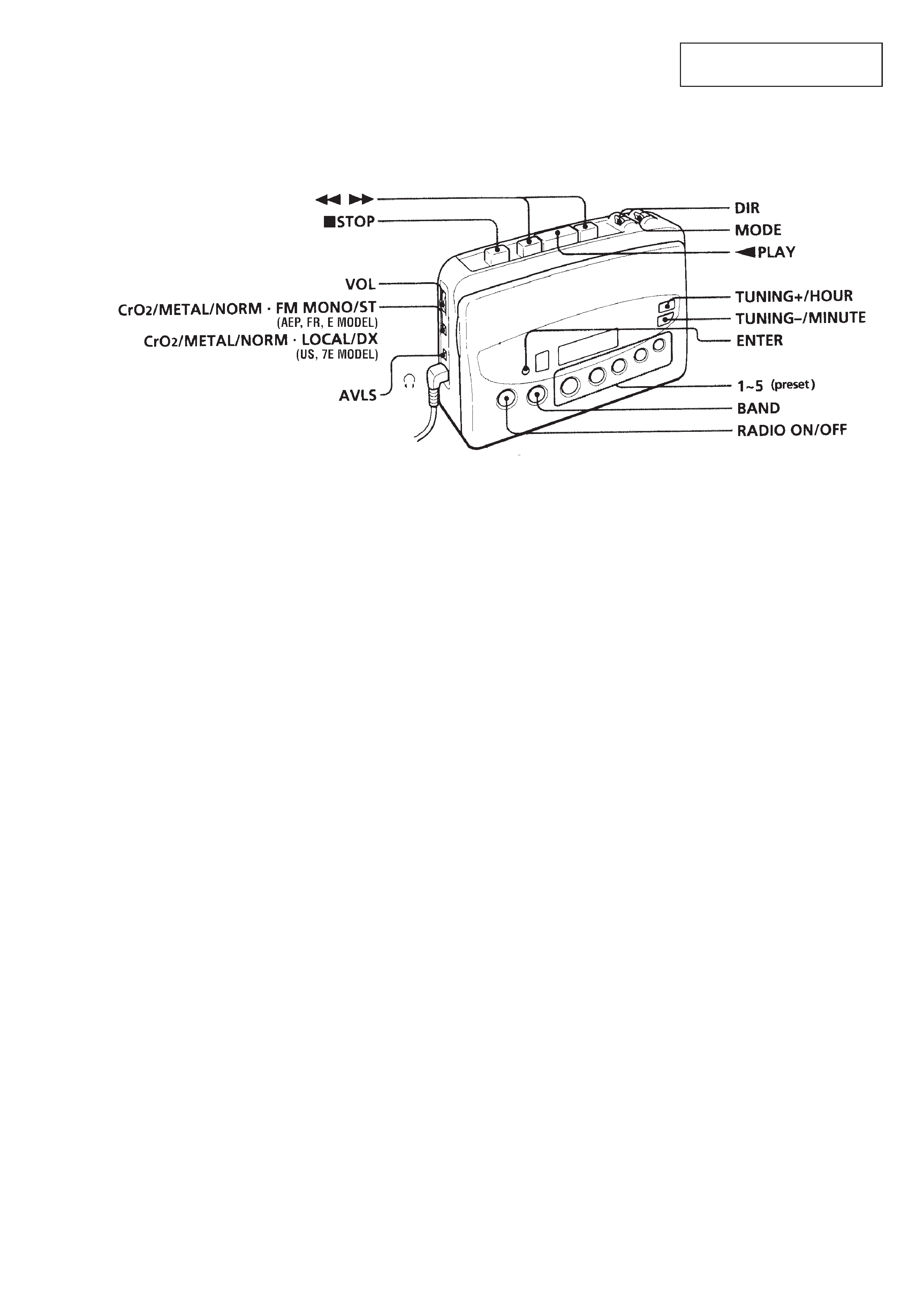
SECTION 1
GENERAL
LOCATION OF PARTS AND CONTROLS
This section is extracted from
instruction manual.
· Abbreviation
FR : French
E
: Radio section : FM MONO/ST switch
7E : Radio section : DX/LOCAL switch
4
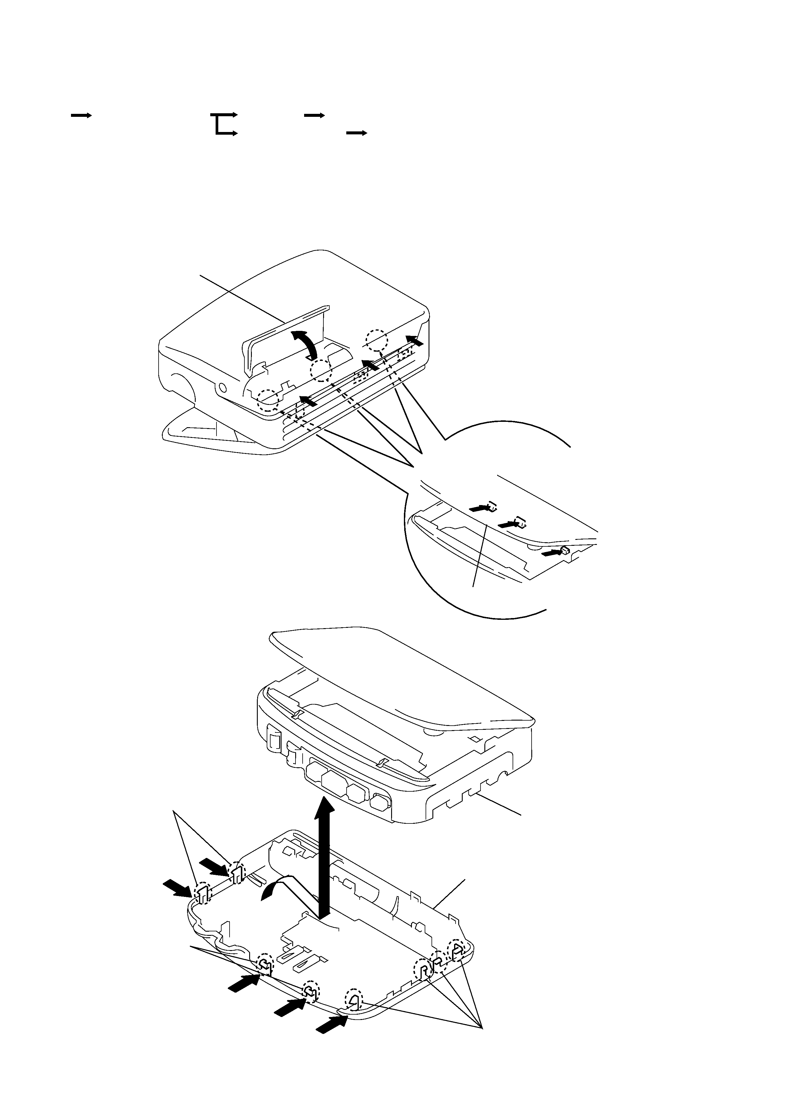
SECTION 2
DISASSEMBLY
Note:Followthedisassemblyprocedureinthenumericalordergiven.
2-1. CABINET (REAR) SUB ASSY REMOVAL
Main board
Cabinet (rear) sub assy
Holder, cassette assy
Mechanism deck
Set
Display board
r
The equipment can be removed using the following procedure.
9
!º
!¡
!TM
!£
8
Claws
Cabinet, Front assy
Claws
Cabinet (Rear) sub assy
Claws
Lid, Batt
3
5
7
6
4
2
1
Holder, Cassette
5
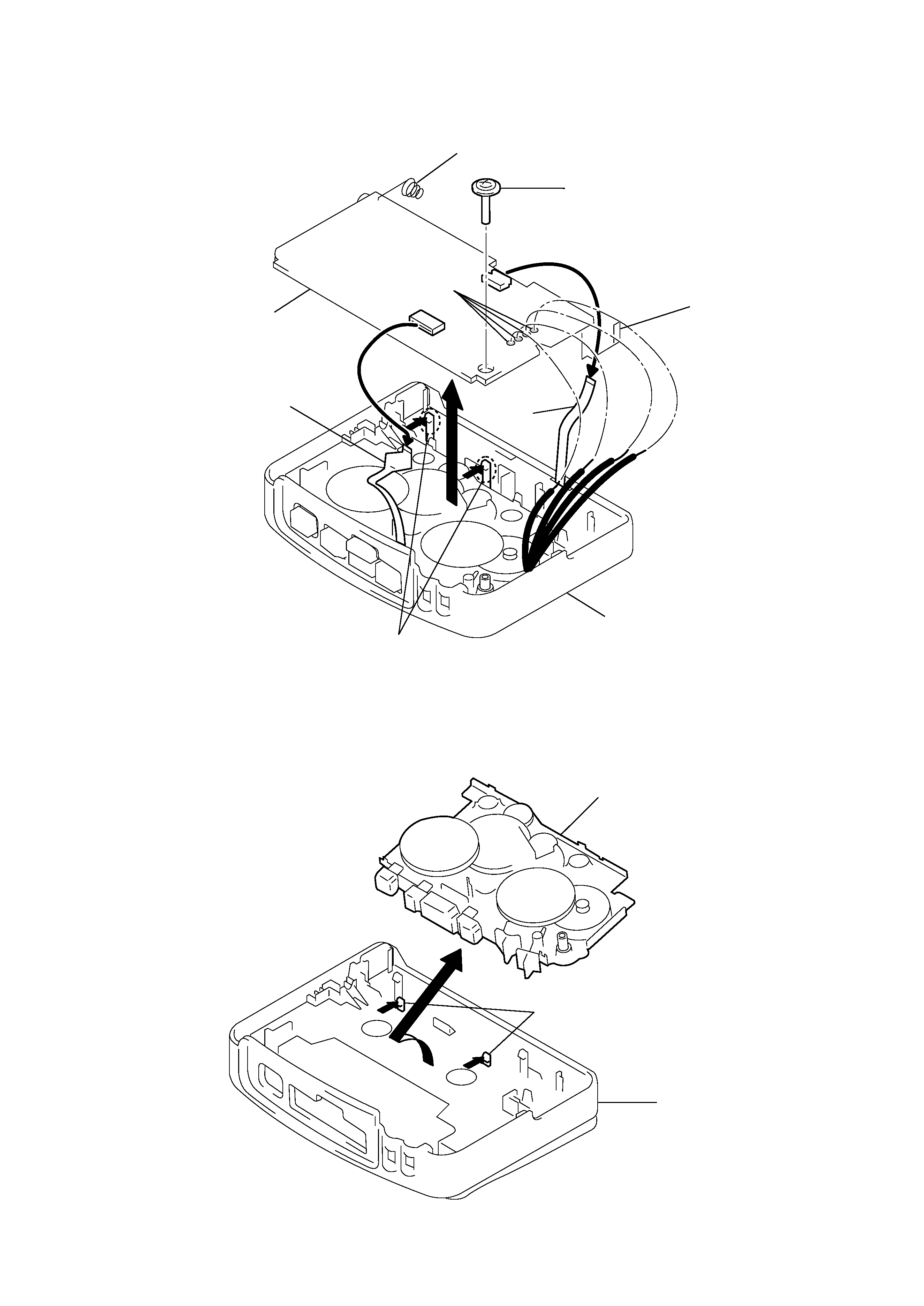
2-2. MAIN BOARD REMOVAL
2-3. MECHANISM DECK REMOVAL
4
5
6
7
3
Terminal (+), Batt
2 Remove solder
1 Screw (M1.4), Tooth (WH)
FPC1
Claws
Cabinet, Front assy
Main board
Flexible board for head
Terminal (), Batt
Mechanism deck
Cabinet, Front assy
1
3
2
Claws