Ver 1.0 2001.03
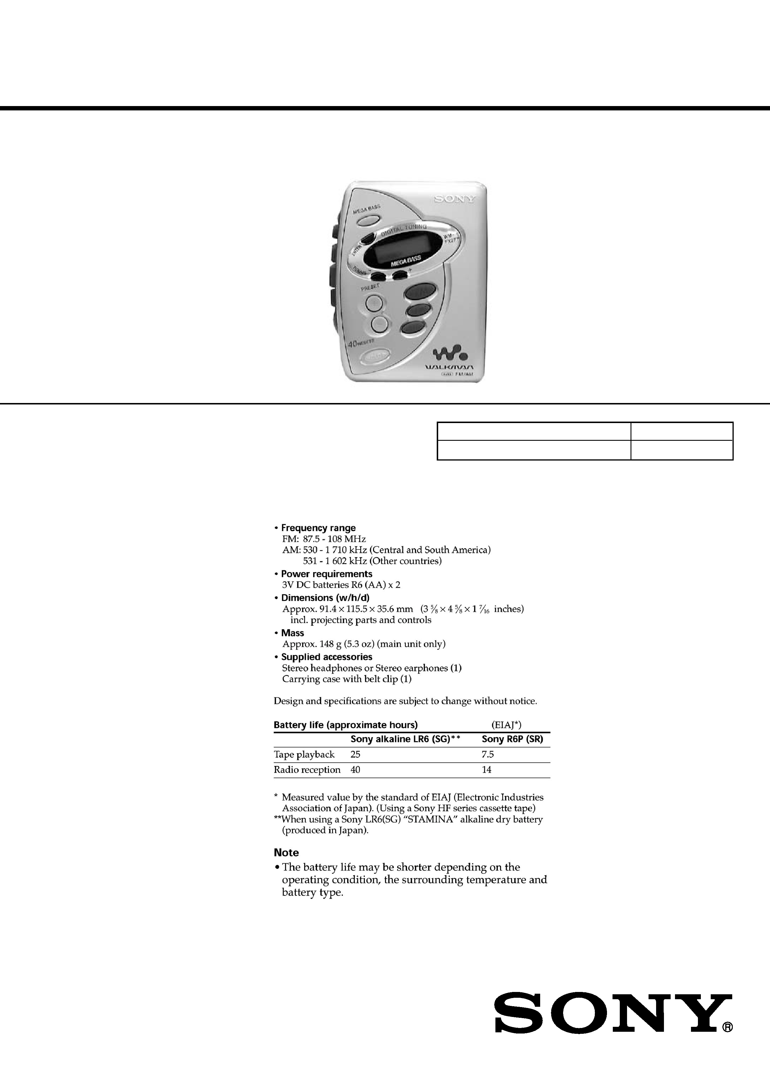
WM-FX277
SERVICE MANUAL
RADIO CASSETTE PLAYER
SPECIFICATIONS
E Model
Chinese Model
Model Name Using Similar Mechanism
NEW
MD Mechanism Type
MF-WMFX241-114
9-927-695-31
2001C0200-1
© 2001.3
Sony Corporation
Audio Entertainment Group
General Engineering Dept.

2
WM-FX277
Specifications ........................................................................... 1
1. SERVICING NOTE ...................................................... 3
2. GENERAL ...................................................................... 3
3. DISASSEMBLY
3-1. Cabinet (Front) ........................................................... 4
3-2. Main Board ................................................................. 4
3-3. Mechanism Deck ........................................................ 5
3-4. Belt, Capstan/reel Motor (M601),
Magnetic Head (Playback) (HP601) ........................... 5
3-5. Cassette Holder ........................................................... 6
4. ADJUSTMENTS
4-1. Mechanical Adjustments ............................................ 7
4-2. Electrical Adjustments ................................................ 7
5. DIAGRAMS
5-1. Explanation of IC Terminals ..................................... 10
5-2. Block Diagram ........................................................... 11
5-3. Printed Wiring Boards Main Section (Side A) ... 12
5-4. Printed Wiring Boards Main Section (Side B) ... 13
5-5. Schematic Diagram ................................................... 14
6. EXPLODED VIEWS
6-1. Cabinet Section ......................................................... 17
6-2. Mechanism Deck Section (MF-WMFX241-114) ..... 18
7. ELECTRICAL PARTS LIST ................................... 19
Flexible Circuit Board Repairing
· Keep the temperature of the soldering iron around 270
°C during
repairing.
· Do not touch the soldering iron on the same conductor of the
circuit board (within 3 times).
· Be careful not to apply force on the conductor when soldering or
unsoldering.
Notes on chip component replacement
· Never reuse a disconnected chip component.
· Notice that the minus side of a tantalum capacitor may be dam-
aged by heat.
TABLE OF CONTENTS
3
WM-FX277
SECTION 1
SERVICING NOTE
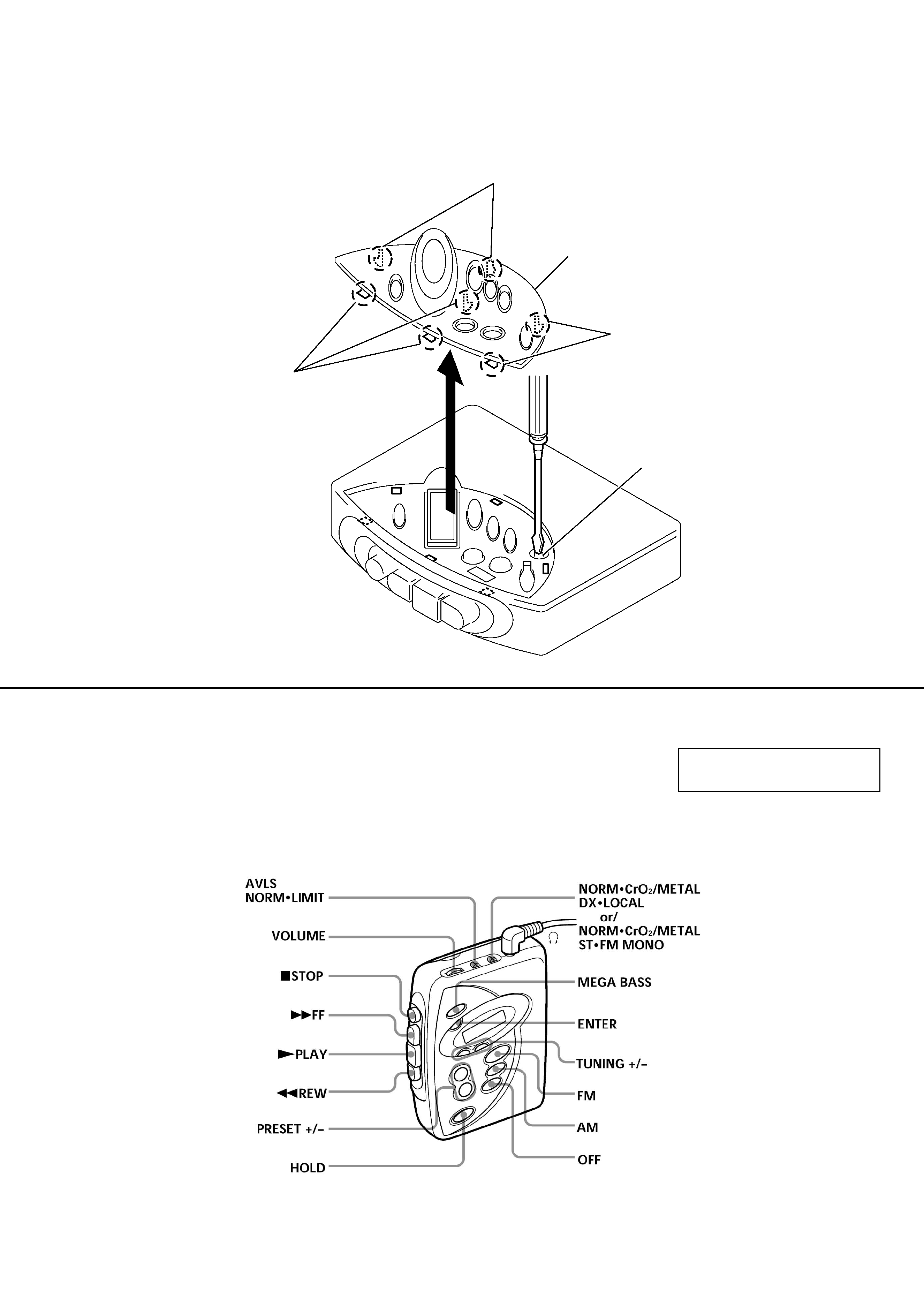
In case of adjusting Tape Speed, you can easily to adjust RV601 by removing 7 claws on Window (LCD) and itself as shown in the figure.
1.Insert the precision screwdriver (Cover a point by cloth) in to the slit at claw.
2.Remove the window(LCD).
Note: Be careful not to damage claws.
Claws
Window(LCD)
Claws
Claws
RV601
SECTION 2
GENERAL
This section is extracted from
instruction manual.
LOCATION AND FUNCTION OF CONTROLS
4
WM-FX277
SECTION 3
DISASSEMBLY
Note : Follow the disassembly procedure in the numerical order given.
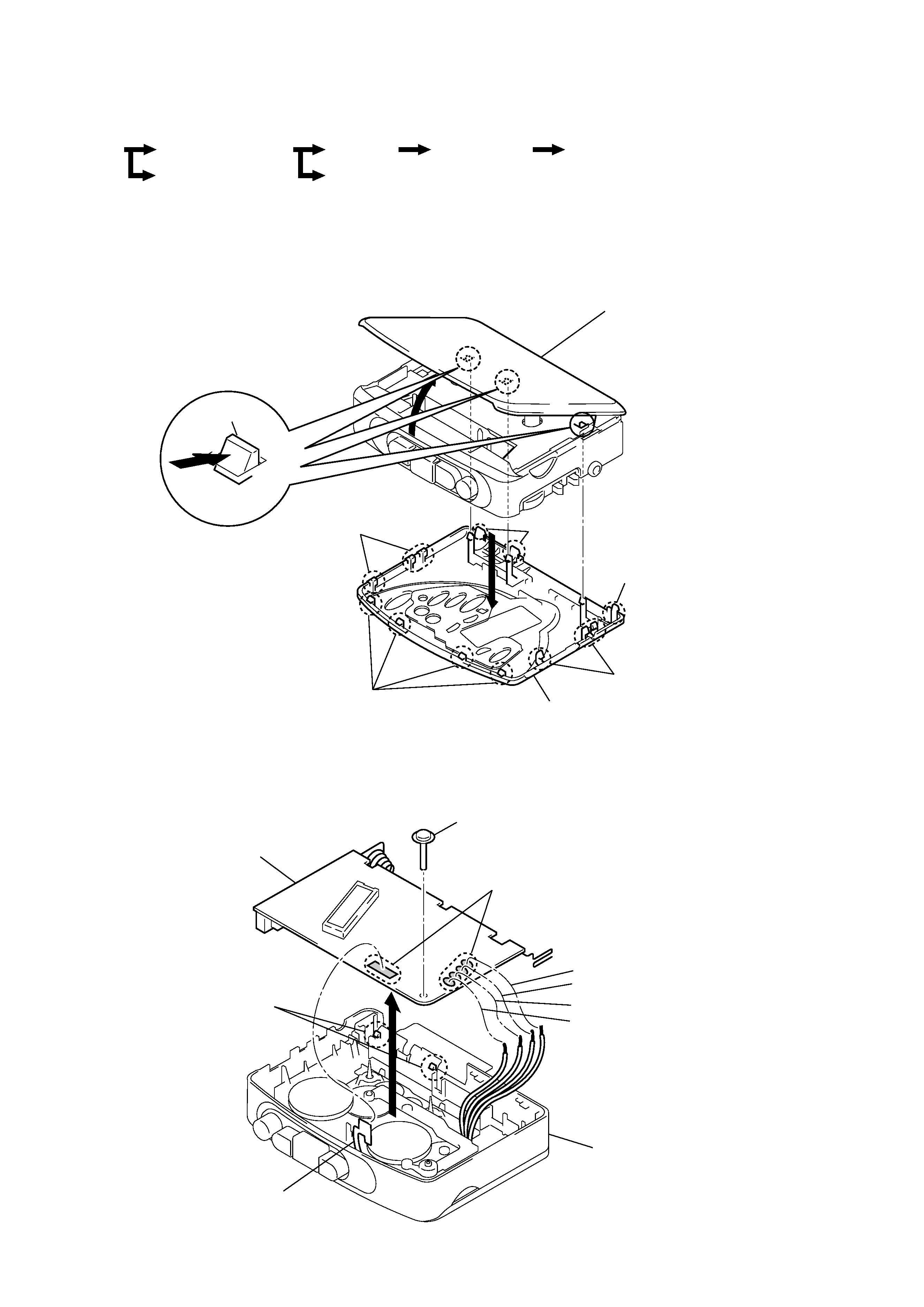
3-1. CASSETT HOLDER ASSY, CABINET (FRONT)
3-2. MAIN BOARD
· The equipment can be removed using the following procedure.
Main board
Cassette holder ASSY
Cabinet (Front)
Cassette holder
Mechanism deck
Belt, Capstan/reel motor (M601),
Magnetic head (Playback) (HP601)
Set
Cabinet (Front)
Cassette holder ASSY
4
Claws
4
Claw
2
5
1
Claws
1
Claws
3
Claws
1
Claws
Main board
1
Screw
Orange
Black
White
Red
Cassette holder ASSY
Head flexible board
2
Remove solder
3
Claws
4
Note : Use the precision driver with coverd a point
by cloth to release the claw.
Be careful not to damage claws.
5
WM-FX277
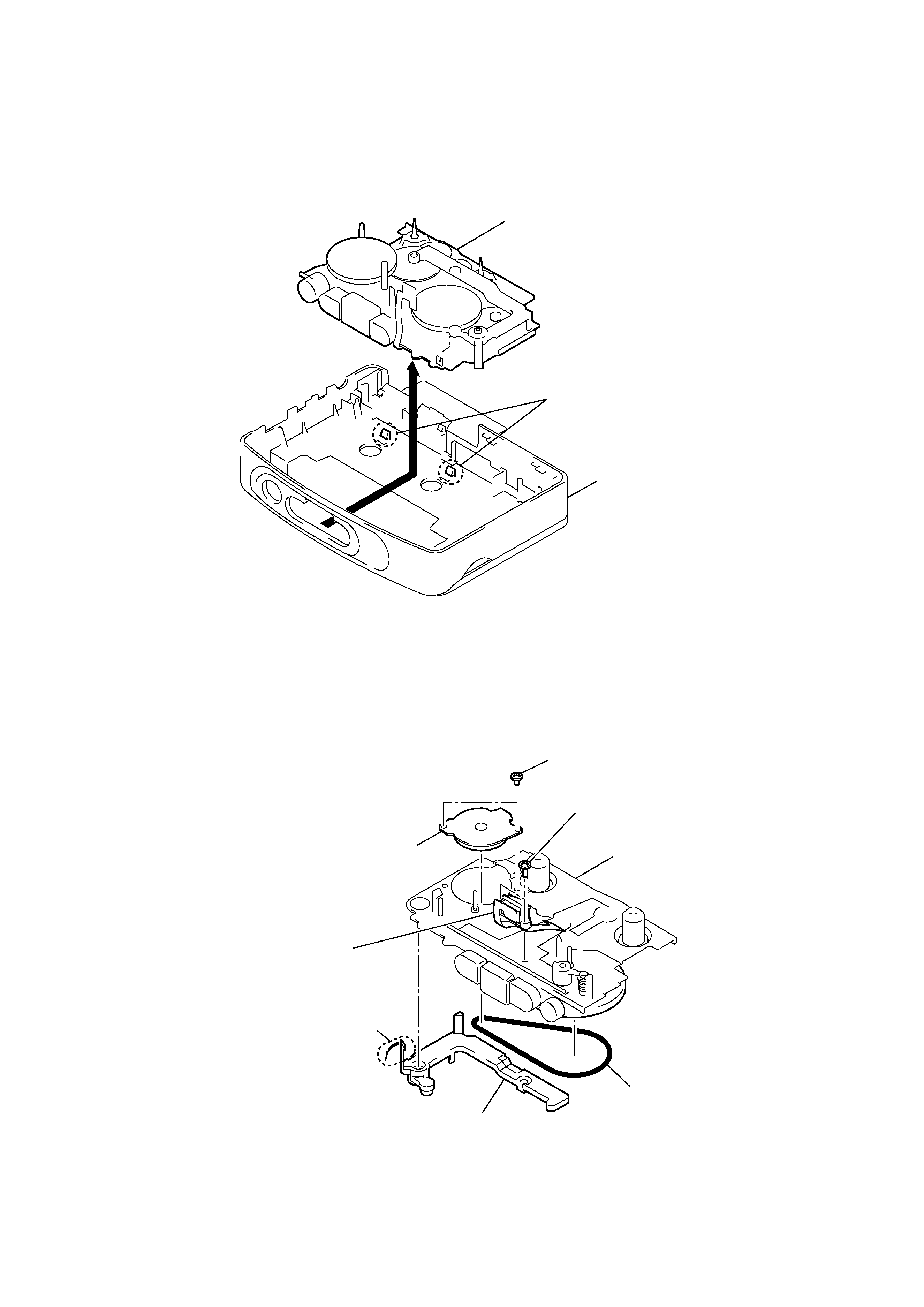
3-3. MECHANISM DECK
3-4. BELT, CAPSTAN/REEL MOTOR (M601), MAGNETIC HEAD (PLAYBACK)(HP601)
Mechanism deck
Cassette holder ASSY
1
Claws
2
2 Belt
Stopper
1 Claw
6 magnetic head
(PLAYBACK)
(HP601)
4
Capstan/reel motor
(M601)
3
Screws (M1.4)
5
Screws (M1.4)
Mechanism deck