WM-FS555/FS555J/FS556
SERVICE MANUAL
SPECIFICATIONS
US Model
WM-FS555/FS555J/FS556
Canadian Model
WM-FS555/FS555J
AEP Model
E Model
WM-FS555
Model Name Using Similar Mechanism
NEW
MD Mechanism Type
MF-WMFS555-114
9-873-595-04
2003F02-1
© 2003.06
Sony Corporation
Personal Audio Company
Pubulished by Sony Engineering Corporation
RADIO CASSETTE PLAYER
Photo : WM-FS555
· Frequency
TV: 2-13 ch
WEATHER: 1-7ch
FM: 87.5-108 MHz
AM: 530-1710 kHz (North, Central and South America)
531-1602 kHz (Other counries)
·Power requirements
1.5 V DC battery size AA (R6)
× 1
· Dimensions
Approx. 102.3
× 117.5 × 47.3 mm (4 1/8 × 4 3/4 × 1 7/8 inches)
including projecting parts and controls
· Mass
Approx. 219 g (7.8 oz) (main unit only)
· Supplied accessories
Stereo headphones or earphones (1)
Hand strap with belt clip (1)
Design and specifications are subject to change witout notice.
Ver 1.3 2003.06
2
WM-FS555/FS555J/FS556
Specifications ........................................................................... 1
1. GENERAL ...................................................................... 2
2. DISASSEMBLY
2-1. Chassis, H/P Board ..................................................... 3
2-2. Main Board ................................................................. 3
2-3. Mechanism Deck ........................................................ 4
2-4. Belt, Capstan/reel Motor (M601),
Magnetic Head (Playback) (HP601) ........................... 4
3. ADJUSTMENTS
3-1. Mechanical Adjustments ............................................ 5
3-2. Electrical Adjustments ................................................ 5
4. DIAGRAMS
4-1. Explanation of IC Terminals ....................................... 8
4-2. Block Diagrams .......................................................... 9
4-3. Printed Wiring Boards Main Section .................. 10
4-4. Schematic Diagram Main Section (1/2) ............... 11
4-5. Schematic Diagram Main Section (2/2) .............. 12
4-6. IC Block Diagrams ................................................... 13
5. EXPLODED VIEWS
5-1. Cassette Lid Section ................................................. 15
5-2. Cabinet Section ......................................................... 16
5-3. Mechanism Deck Section
(MF-WMFS555-114) ............................ 17
6. ELECTRICAL PARTS LIST ................................... 18
Flexible Circuit Board Repairing
· Keep the temperature of the soldering iron around 270
°C during
repairing.
· Do not touch the soldering iron on the same conductor of the
circuit board (within 3 times).
· Be careful not to apply force on the conductor when soldering or
unsoldering.
Notes on chip component replacement
· Never reuse a disconnected chip component.
· Notice that the minus side of a tantalum capacitor may be dam-
aged by heat.
TABLE OF CONTENTS
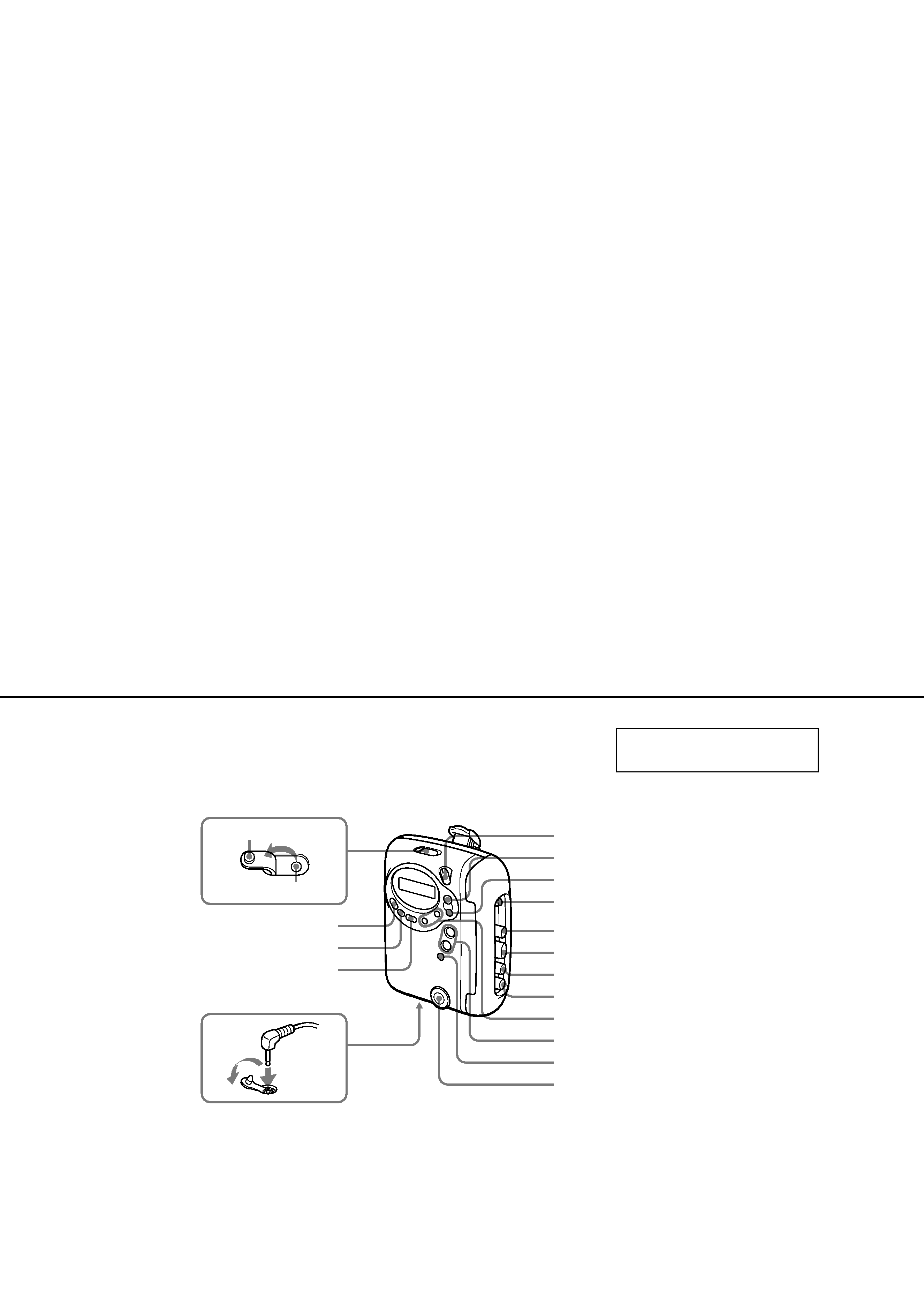
SECTION 1
GENERAL
TV/WEATHER (US), FM (EXCEPT US)
HOLD
VOLUME*
TUNING+/
x
Y
PRESET +/
FM/AM (US), AM (EXCEPT US)
RADIO OFF
M
n
**
m
MENU
SET
ENTER
Rubber cap
Air outlet
i
* There is a tactile dot beside VOLUME on the main unit to
show the direction to turn up the volume.
** The button has a tactile dot.
This section is extracted from
instruction manual.
3
WM-FS555/FS555J/FS556
2
Two screws
(B1.7 × 8)
1
Open the "lid, Cassette"
H/P board
5
3
Claws
Cabinet (rear) sub ASSY
Chassis
4
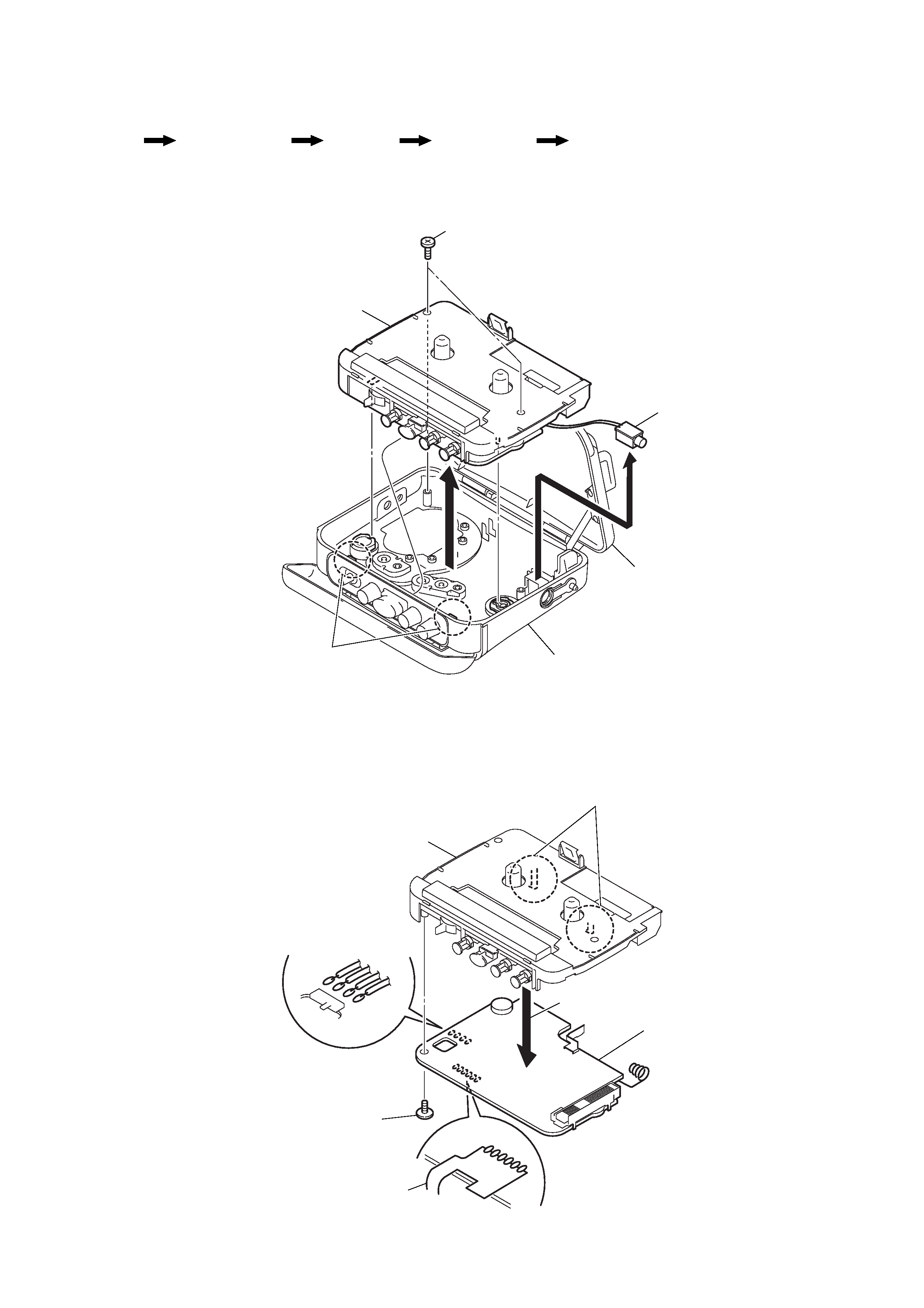
SECTION 2
DISASSEMBLY
Note : Follow the disassembly procedure in the numerical order given.
2-1. CHASSIS, H/P BOARD
2-2. MAIN BOARD
z
The equipment can be removed using the following procedure.
Main board
Chassis, H/P board
Mechanism deck
Belt, Capstan/reel motor (M601),
Magnetic head (playback) (HP901)
Set
1
Remove solder
(four places)
3
Screw
(WH M1.4)
2
Remove solder
(six places)
4
Claws
5
Main board
Head flexible board
Chassis
4
WM-FS555/FS555J/FS556
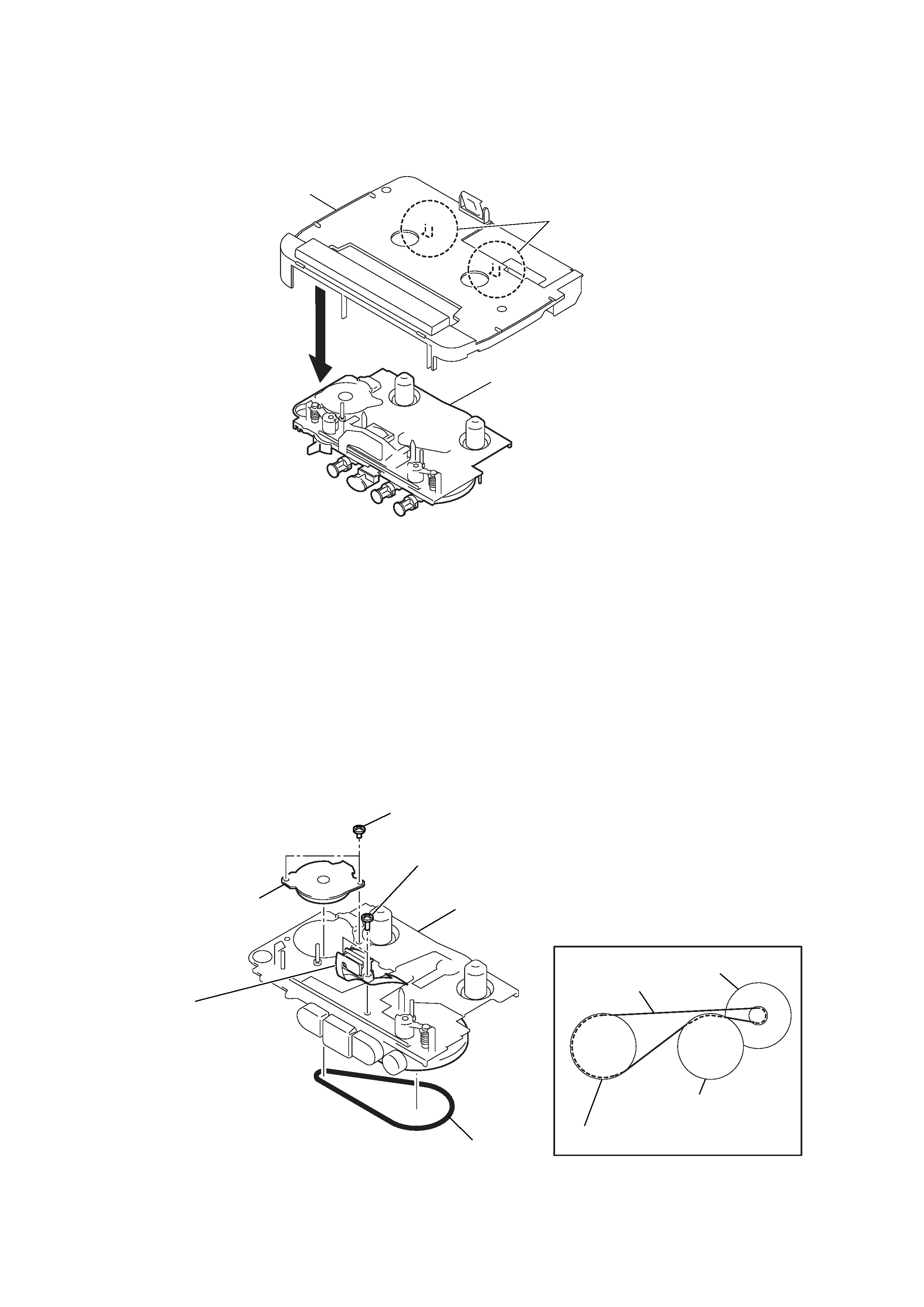
2-3. MECHANISM DECK
2-4. BELT, CAPSTAN/REEL MOTOR (M601), MAGNETIC HEAD (PLAYBACK) (HP901)
1
Claws
Mechanism deck
Chassis
2
wheel ASSY (P), capstan
wheel ASSY (P), capstan
Belt
· How to apply the belt
Capstan/reel motor
(M601)
1 Belt
5 magnetic head
(PLAYBACK)
(HP901)
3
Capstan/reel motor
(M601)
2
Two screws (M1.4)
4
Two screws (M1.4)
Mechanism deck
5
WM-FS555/FS555J/FS556
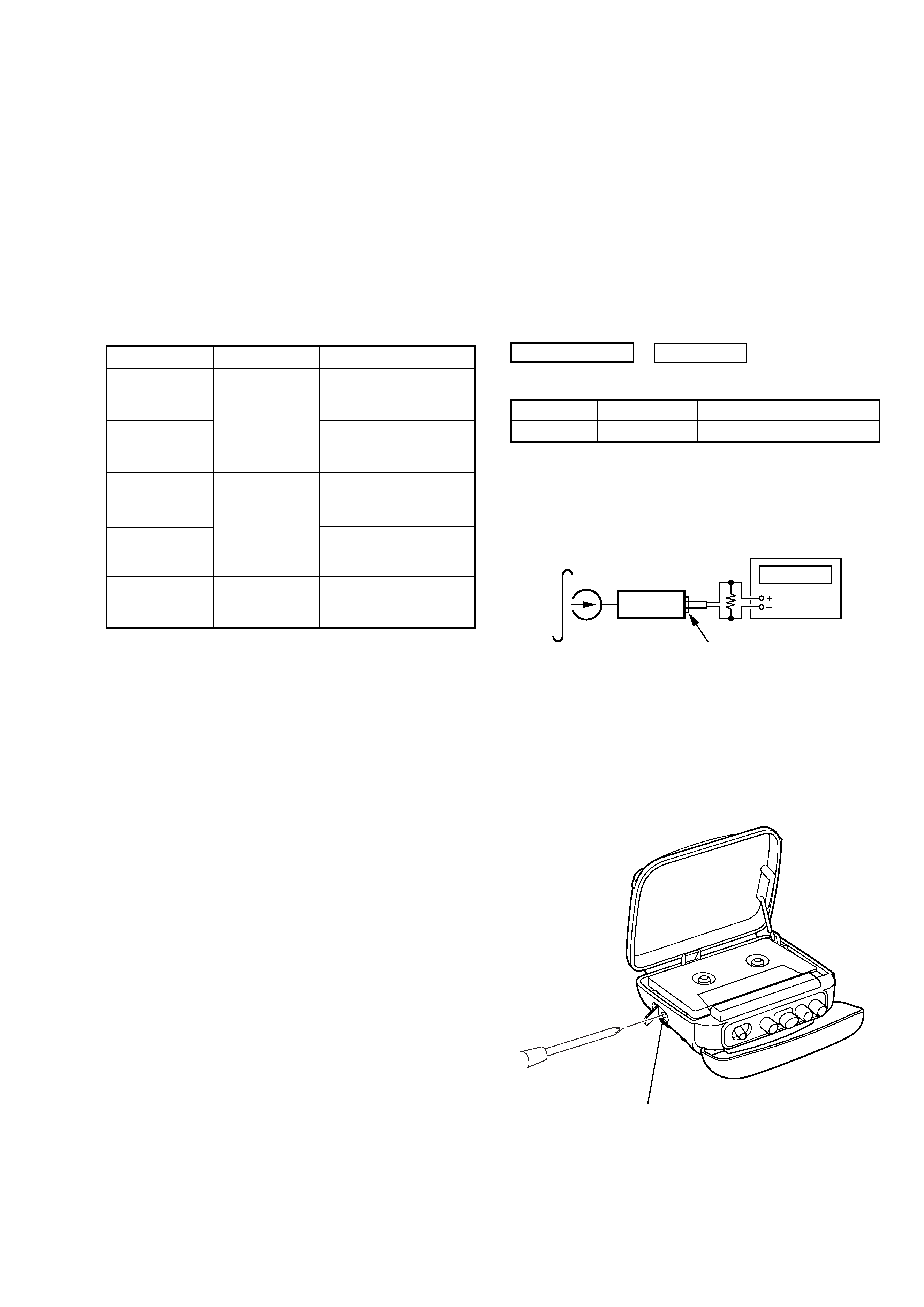
3-2. ELECTRICAL ADJUSTMENTS
PRECAUTION
· Supplied voltage : 1.5 V.
· Switch and control position (MENU display)
MEGA BASS : OFF
VOLUME control (RV301) : maximum
AVLS : OFF (No indicated)
FM MODE : US : DX (No indicated)
Canadian, AEP, E : STEREO (No indicated)
TAPE SECTION
Test Tape
Type
Signal
Used for
WS-48A
3kHz, 0dB
Tape Speed Adjustment
Tape Speed Adjustment
Procedure :
1. Playback WS-48A (tape center part) in the FWD state and ad-
just RV601 so that the frequency counter reading becomes
3,000Hz.
Standard value : 2,9853,015Hz
2. Playback WS-48A (tape center part) in the REV state.
Check that frequency counter reading is within
±1.0% of the
reading of step 1.
Adjustment Location :
3-1. MECHANICAL ADJUSTMENTS
PRECAUTION
1. Clean the following parts with a denatured-alcohol-moistened
swab :
playback head
pinch roller
capstan
rubber belt
2. Demagnetize the playback head with a head demagnetizer.
Do not use a magnetized screwdriver for the adjustments.
3. These measurement and adjustment should be performed with
the rated power supply voltage (1.5 V) unless otherwise noted.
Torque Measurement
Mode
Torque meter
Meter reading
FWD
1.97 4.11 mN · m
20 42 g · cm
(0.28 0.58 oz· inch)
FWD
CQ-102C
less than 0.19 mN · m
less than 2 g · cm
back tension
(less than 0.027 oz· inch)
1.97 4.11 mN · m
REV
20 42 g · cm
(0.28 0.58 oz· inch)
REV
CQ-102RC
less than 0.19 mN · m
less than 2 g · cm
back tension
(less than 0.027 oz· inch)
FF, REW
CQ-201B
more than 3.93 mN · m
more than 40 g · cm
(more than 0.56 oz· inch)
SECTION 3
ADJUSTMENTS
0 dB = 0.775V
set
test tape
WS-48A
(3kHz, 0dB)
frequency counter
16
phones jack (J301)
RV601: Tape speed Adjustment