Ver 1.0
1998. 05
MICROFILM
WM-FS473
SERVICE MANUAL
SPECIFICATIONS
US Model
Canadian Model
AEP Model
E Model
Model Name Using Similar Mechanism
NEW
Tape Transport Mechanism Type
MF-WMFS473
Frequency range
FM
: 87.5 108 MHz
AM : 530 1710kHz
(US, Canadian model)
531 1602kHz (AEP, E model)
Power requirements
3V DC batteries (AA) R6 x2
Dimensions
104.2 x 127.3 x 51.8 mm (4 1/8 x 51/8 x 21/8 inches)
(w/h/d) incl. projecting parts and controls
Mass
Approx. 260g (9.2 oz)
Approx.340g (12 oz) incl. batteries and a cassette
Supplied accessory
Stereo headphones or Stereo earphones (1)
Design and specifications are subject to change without notice.
RADIO CASSETTE PLAYER
2
Flexible Circuit Board Repairing
· Keep the temperature of the soldering iron around 270
°C
during repairing.
· Do not touch the soldering iron on the same conductor of the
circuit board (within 3 times).
· Be careful not to apply force on the conductor when soldering
or unsoldering.
Notes on chip component replacement
· Never reuse a disconnected chip component.
· Notice that the minus side of a tantalum capacitor may be
damaged by heat.
TABLE OF CONTENTS
Specifications ........................................................................... 1
1. GENERAL
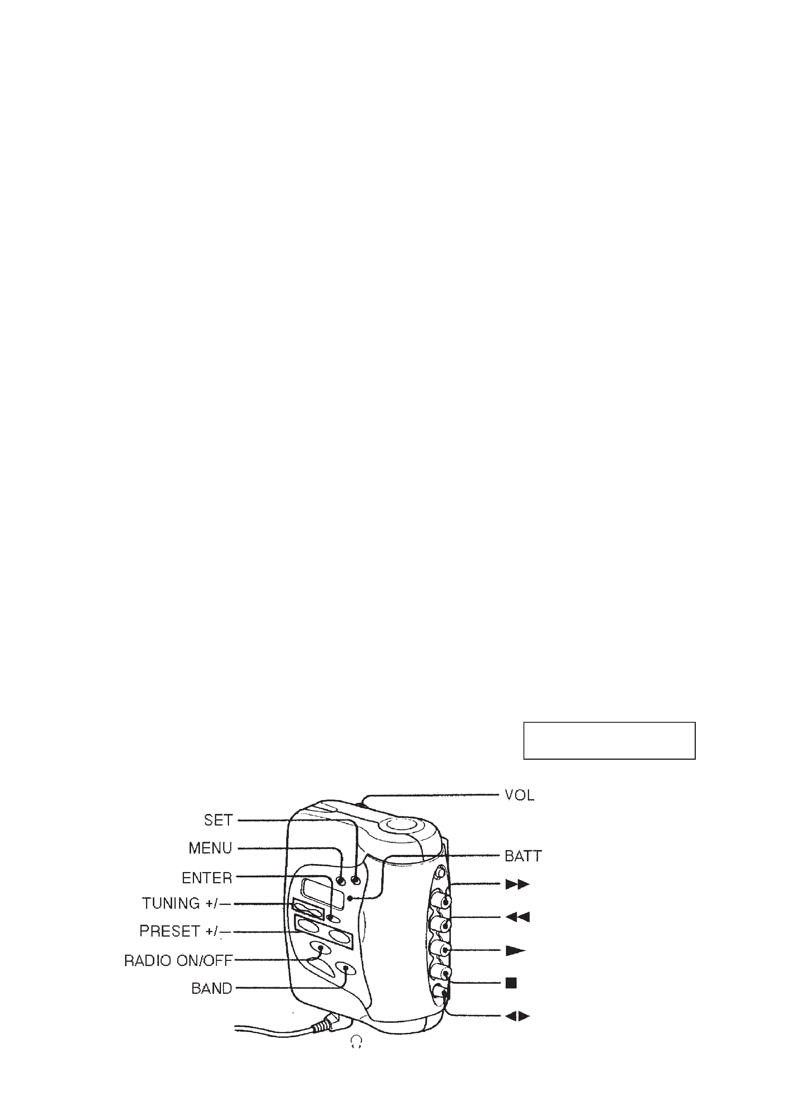
Location of parts and controls ............................................ 2
2. SERVICE NOTE ........................................................... 3
3. DISASSEMBLY
3-1. Cover Removal ........................................................... 4
3-2. Display Board Removal ............................................. 4
3-3. Cassette Lid Assy Removal ........................................ 5
3-4. Chassis section, Headphone Jack Board Removal ..... 5
3-5. Mechanism Deck, Main Board, Belt Removal ........... 6
4. ADJUSTMENTS
4-1. Mechanical Adjustments ............................................ 7
4-2. Electrical Adjustments ................................................ 7
5. DIAGRAMS
5-1. Explanation of IC Terminals ..................................... 10
5-2. Block Diagram ........................................................... 11
5-3. Printed Wiring Boards (Main Section) ..................... 13
5-4. Schematic Diagram (Main Section) ......................... 15
5-5. Schematic Diagram (Display Section) ..................... 18
5-6. Printed Wiring Boards (Display Section) ................. 21
6. EXPLODED VIEWS
6-1. Cassette Lid Section ................................................. 23
6-2. Main Board Section .................................................. 24
6-3. Mechanism Deck Section (MF-WMFS473) ............ 25
7. ELECTRICAL PARTS LIST ................................... 26
SECTION 1
GENERAL
This section is extracted from
instruction manual.
3
SECTION 2
SERVICE NOTE
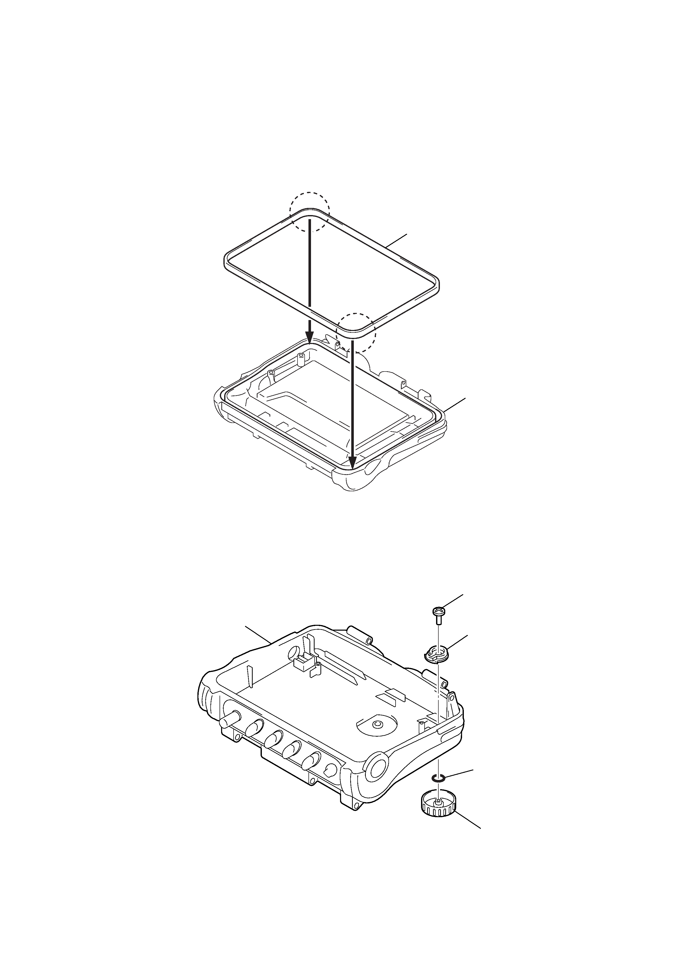
WATERPROOFED SECTION
Set the Apositions to corner.
then push down to grove.
Note : In case the parts in the figure are removed for repair, treat them to protect from water drop following the instructions in the figure
(spread grease, bond etc.)
· Sony grease SGL-601 : 7-651-000-10
Note : Clean the attachement portion
and shaded area with cloth.
Paking (cabinet)
A
A
Cassette lid assy
Screw
Joint (VOL. B)
O ring
(Apply sony grease SGL-601)
Knob (VOL)
Cabinet (rear) assy
4
SECTION 3
DISASSEMBLY
Note :Followthedisassemblyprocedureinthenumericalordergiven.
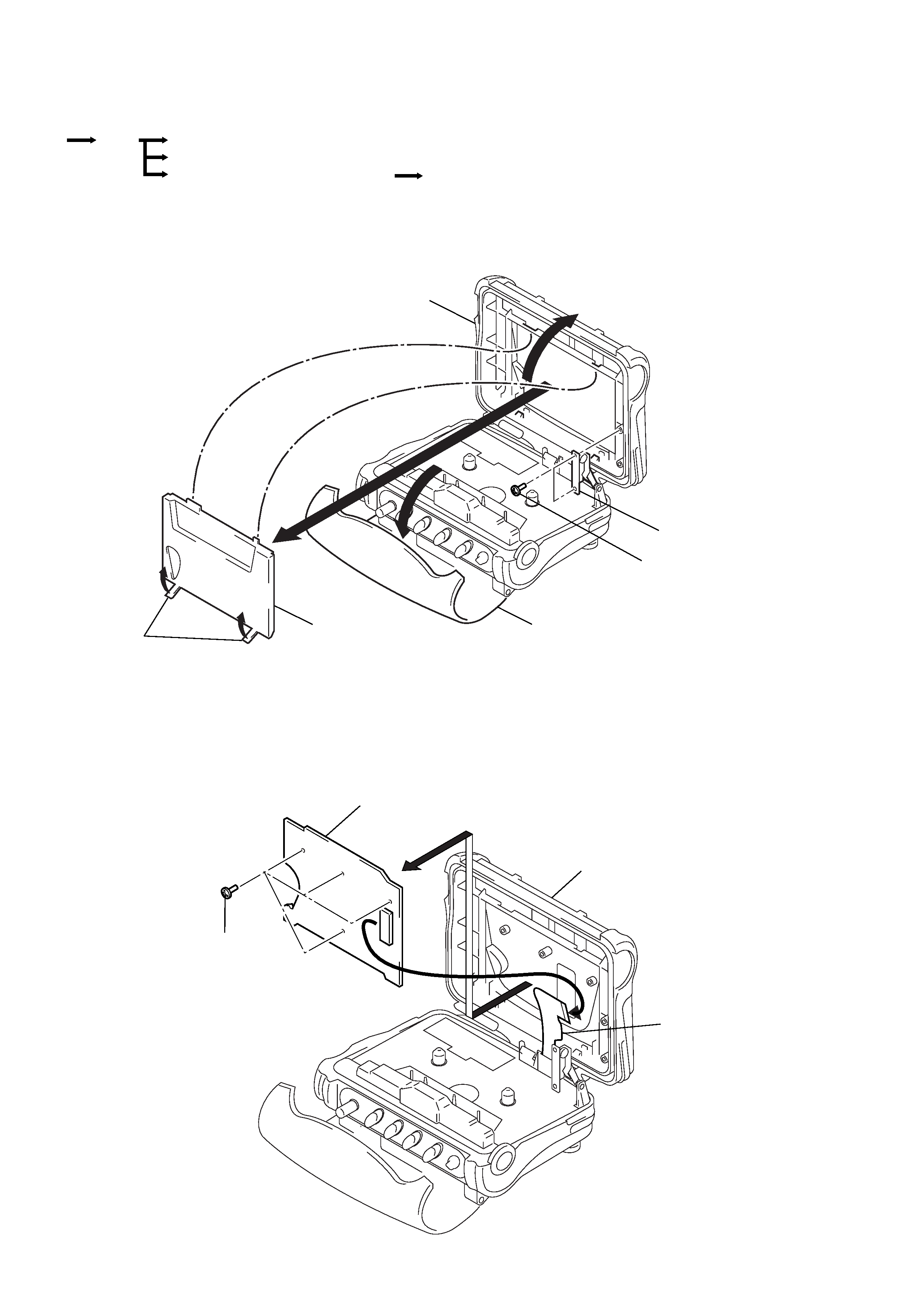
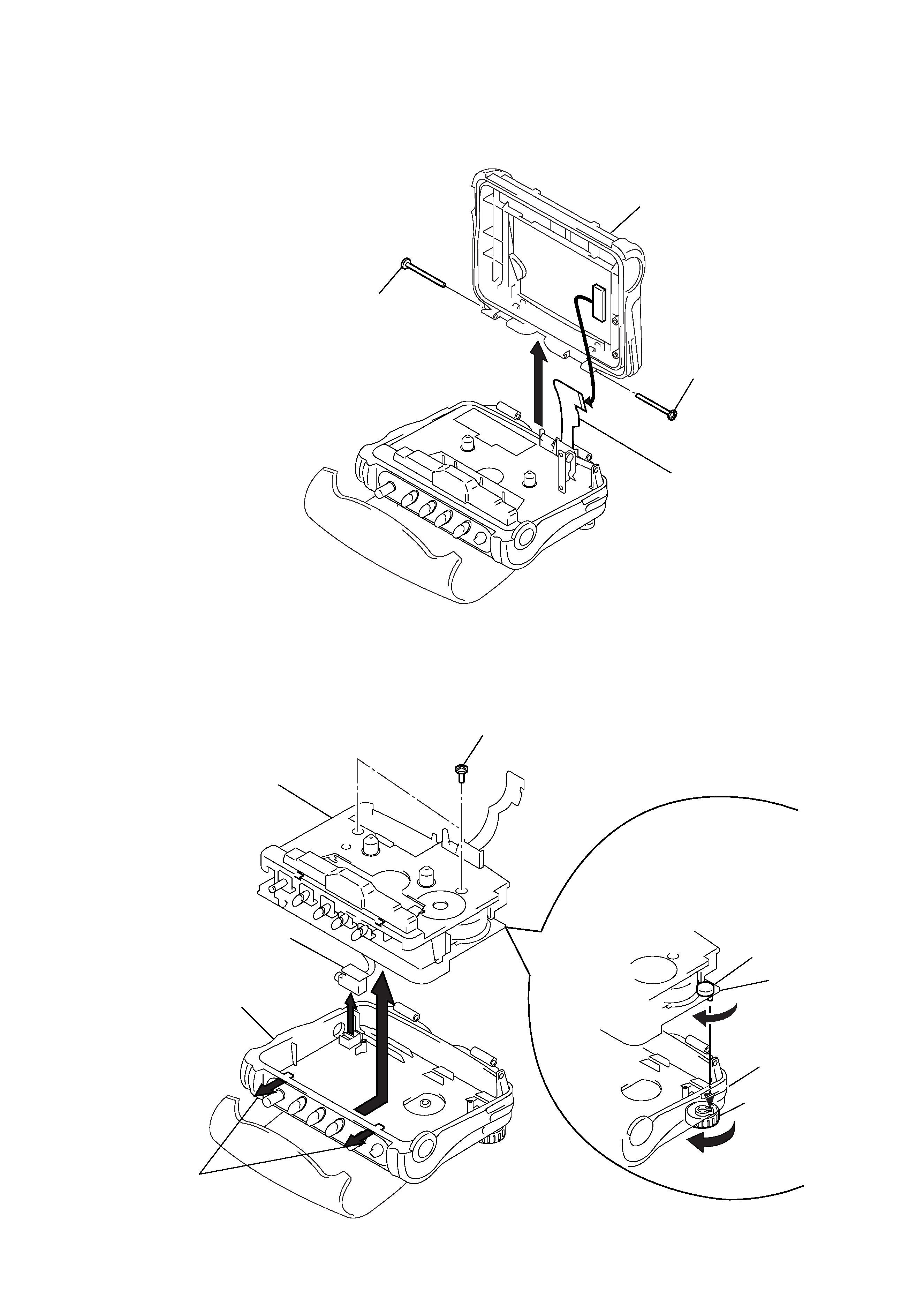
3-1. COVER REMOVAL
3-2. DISPLAY BOARD REMOVAL
r
Theequipmentcanberemo
vedusingthef
ollo wingpr ocedure .
Cassette lid assy
3
2 Screws
1 Flexible board
Display board
Cassette lid assy
Arm assy
Backle
Cover
5 Screws
4
2
1
3 Claws
Chassis section, Headphone jack board
Cover
Set
Diaplay board
Cassette lid assy
Mechanism deck, Main board, Belt
5
3-3. CASSETTE LID ASSY REMOVAL
3-4. CHASSIS SECTION, HEADPHONE JACK BOARD REMOVAL
1 Screws (+P 2x12)
4
3
3
1
2
Headphone jack board
Chassis section
Cabinet (rear) assy
Cabinet (rear) assy
Knob (VOL)
RV301
Main board
2 Claws
Cassette lid assy
2 Screw
2 Screw
3
1 Flexible board
Note :Wheninstallthec
hassissection
1. TurnR V301full yto arr ow direction.
2. Turn knob (V OL) full y to arr ow direction.
3. Fit R V301 to hole of knob (V
OL) and then
installthechassissection.