MICROFILM
WM-FQ01
SERVICE MANUAL
RADIO CASSETTE PLAYER
SPECIFICATIONS
US Model
Canadian Model
AEP Model
Radio
US, Canadian model :
FM
: 87.6 108MHz
AM
: 530 1,710kHz
AEP model :
FM
: 87.6 107.9MHz
AM
: 531 1,602kHz
Power Requirements
· 3V DC Batteries R6 (AA) x 2
· External DC 3V power sources
Battery life
(approximate hours)
(EIAJ*)
Sony Alkaline LR6 (SG)
Sony R6P (SR)
16 hours. (playback)
4.5 hours. (playback)
48 hours. (radio)
16 hours. (radio)
* Measured value by the standard of EIAJ (Electronic Industries
Association of Japan). (Using Sony HF series cassette tape)
Dimensions
118.8 x 89.5 x 34.1 mm (4 3/4 x 3 5/8 x 1 3/8in)
(w/h/d) incl. projecting parts
Mass
205g (7.3 oz) incl. batteries
Supplied accessories
· Stereo headphones (1)
· Belt clip (1)
· Protecter (1)
Design and specifications are subject to change without notice.
Model Name Using Similar Mechanism
WM-FX321
Tape Transport Mechanism Type
MF-WMFX305-43
2
Specifications ........................................................................... 1
1. GENERAL
Location and Function of Controls .................................... 2
2. DISASSEMBLY
2-1. Cabinet (Rear) Removal ............................................. 3
2-2. Cabinet (Front) Removal ............................................ 3
2-3. Main Board, Mechanism Deck Removal ................... 3
2-4. Cassette Holder Sub Assy Removal ........................... 4
2-5. Dial Pointer Setting .................................................... 4
3. ADJUSTMENTS
3-1. Mechanical Adjustment .............................................. 5
3-2. Electrical Adjustment ................................................. 5
4. DIAGRAMS
4-1. Block Diagram ............................................................ 7
4-2. Printed Wiring Boards ................................................ 9
4-3. Schematic Diagram .................................................... 11
5. EXPLODED VIEWS
5-1. Cabinet and Board Section ....................................... 15
5-2. Mechanism Deck Section ......................................... 16
6. ELECTRICAL PARTS LIST ................................ 17
Flexible Circuit Board Repairing
· Keep the temperature of the soldering iron around 270
°C during
repairing.
· Do not touch the soldering iron on the same conductor of the
circuit board (within 3 times).
· Be careful not to apply force on the conductor when soldering or
unsoldering.
Notes on chip component replacement
· Never reuse a disconnected chip component.
· Notice that the minus side of a tantalum capacitor may be dam-
aged by heat.
TABLE OF CONTENTS
· HOW TO CHANGED THE CERAMIC FILTERS
This model is used two ceramic filters of CF2 and X2.
You must used same type of color marked ceramic filters in order
to meet same specifications.
Therefore, the ceramic filter must changed two pieces together
since it's supply two pieces in one package as a spare parts
mark
mark
CF2
X2
Mark
Center Frequency
red
10.70MHz
blue
10.67MHz
orange
10.73MHz
black
10.64MHz
white
10.76MHz
SECTION 1
GENERAL
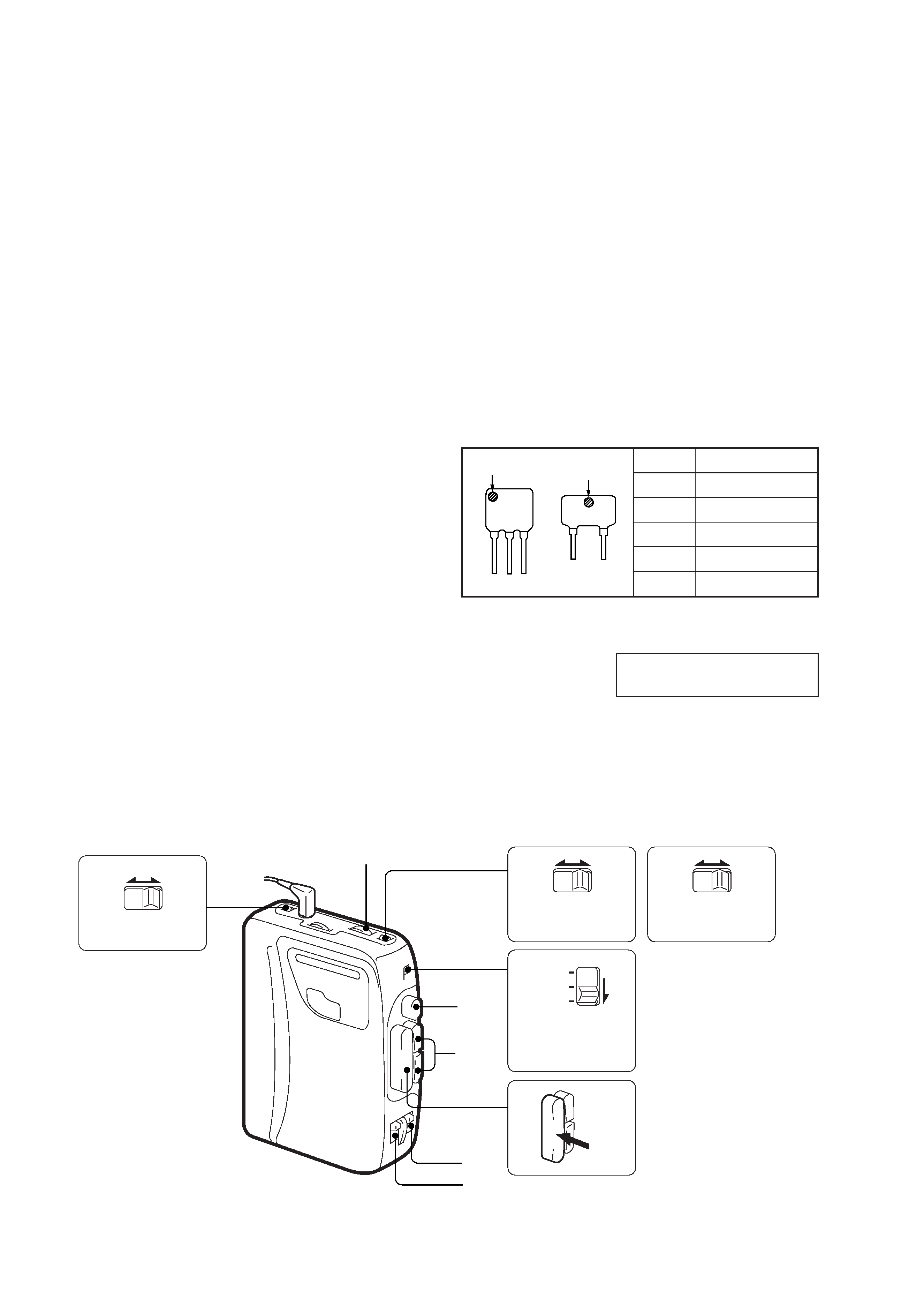
LOCATION AND FUNCTION OF CONTROLS
This section is extracted from
instruction manual.
··
NORM LIMIT
AVLS
··
NORM CrO2/
METAL
DX LOCAL
··
NORM CrO2/
METAL
ST MONO
FM
AM
T
APE
(RADIO
OFF)
PLAY
DIR
MODE
VOLUME
p
0 )
US, Canadian model
AEP model
3
SECTION 2
DISASSEMBLY
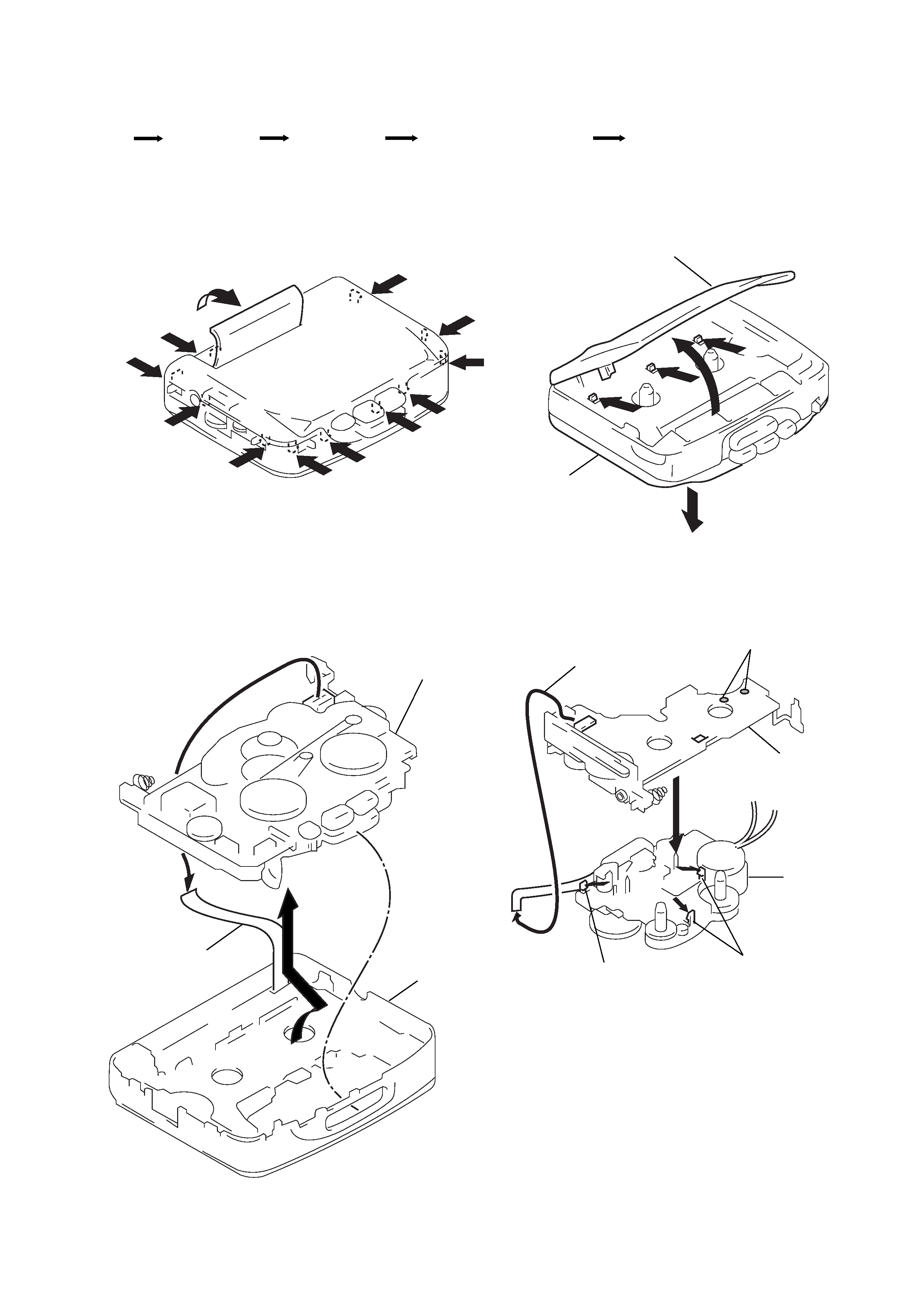
Note :Follow the disassembly procedure in the numerical order given.
r The equipment can be removed using the following procedure.
2-1. CABINET (REAR) REMOVAL
2-2. CABINET (FRONT) REMOVAL
Main board, Mechanism deck
Cabinet (Front)
Cabinet (Rear)
Cassette holder sub assy
Set
Cassette holder sub assy
Cabinet (Rear)
1
2
2
3
3
7
7
7
7
7
4
4
6
6
6
5
8
Cabinet (Front)
Main board and
Mechanism deck
1 Flexible board
2
2-3. MAIN BOARD, MECHANISM DECK REMOVAL
Main board
Mechanism deck
1 Remove solder
2 Head flexible board
3 Claw
3 Claws
4
4
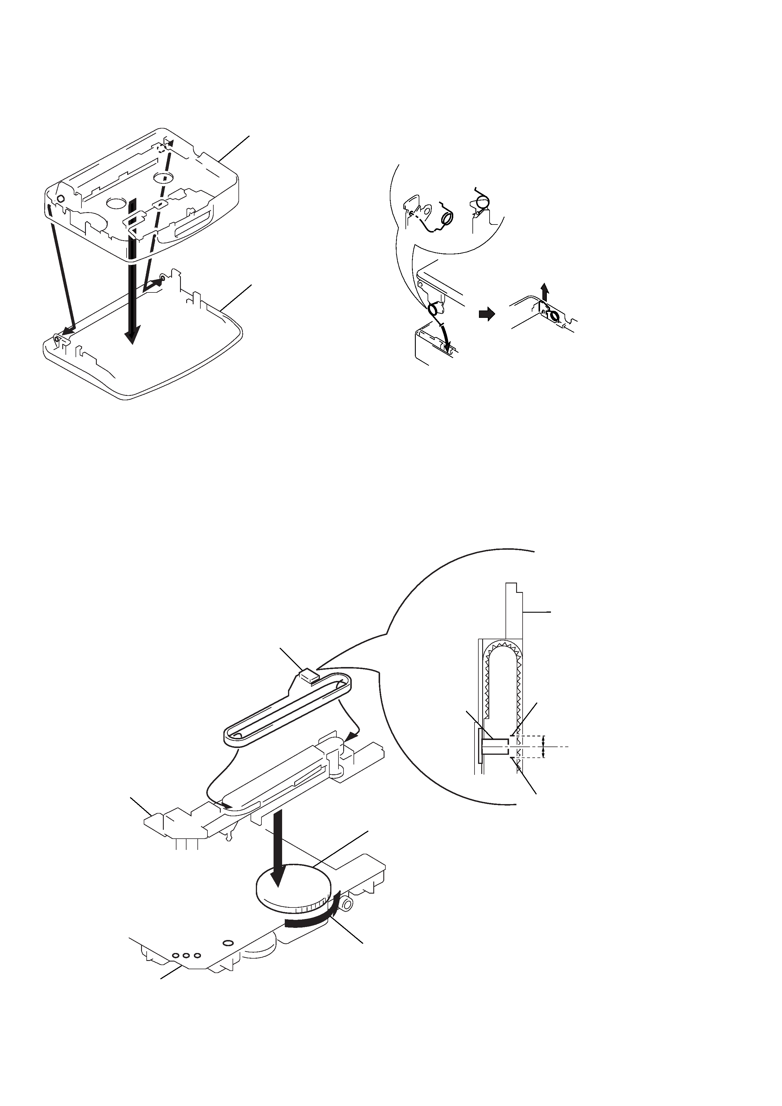
2-5. DIAL POINTER SETTING
2-4. CASSETTE HOLDER SUB ASSY REMOVAL
NOTE FOR INSTALLATION
The torsion spring will be removed together with the cassette lid that
preform the following for installation.
r
TORSION SPRING
Cabinet (Front)
Cassette holder sub assy
2
3
1
2 Align pointer with arrow marked
side as shown in Fig. 1 and then
fit to groove in the order of
a and b.
1 Rotate tune knob fully to arrow direction.
3
Align point
Ferrite-rod antenna sub assy
A
B
(A=B)
Align point
Pointer
b
a
Fig. 1
Pointer
Ferrite-rod antenna sub assy
Knob (tune)
Main board
1 Attach the torsion spring
as shown in the figure
2 Insert the torsion spring
in the hole as shown in the figure.
3 Lift the torsion spring in
the arrow direction and
hook it properly
5
SECTION 3
ADJUSTMENTS
3-1. MECHANICAL ADJUSTMENTS
PRECAUTION
1. Clean the following parts with a denatured-alcohol-moistened
swab :
playback head
pinch roller
capstan
rubber belt
2. Demagnetize the playback head using a head demagnetizer.
3. Do not use a magnetized screwdriver for adjustments.
4. After the adjustments, apply suitable locking compound to the
parts adjusted.
5. The adjustments should be performed with the rated power sup-
ply voltage (2.5V) unless otherwise noted.
Torque Measurement
Torque
Torque Meter
Meter Reading
FWD
20 42 g · cm
CQ-102C
(0.28 0.58 oz· inch)
FWD
less than 2 g · cm
back tension
(less than 0.03 oz· inch)
REV
20 42 g · cm
CQ-102RC
(0.28 0.58 oz· inch)
REV
less than 2 g · cm
back tension
(less than 0.03 oz· inch)
FF, REW
CQ-201B
more than 60g · cm
(more than 0.83 oz· inch)
Tape Pulling Force Measurement
Mode
Torque Meter
Meter Reading
FWD
CQ-403A
more than 40 g
REV
CQ-403R
(more than 1.42 oz)
3-2. ELECTRICAL ADJUSTMENTS
PRECAUTION
· Specified voltage
: 2.5V.
· Switch and control position
TAPE switch
: NORM
VOLUME control
: maximum
AVLS switch
: NORM
Function switch
: TAPE
TAPE SECTION
Test Tape
Type
Signal
Used for
WS-48A
3kHz, 0dB
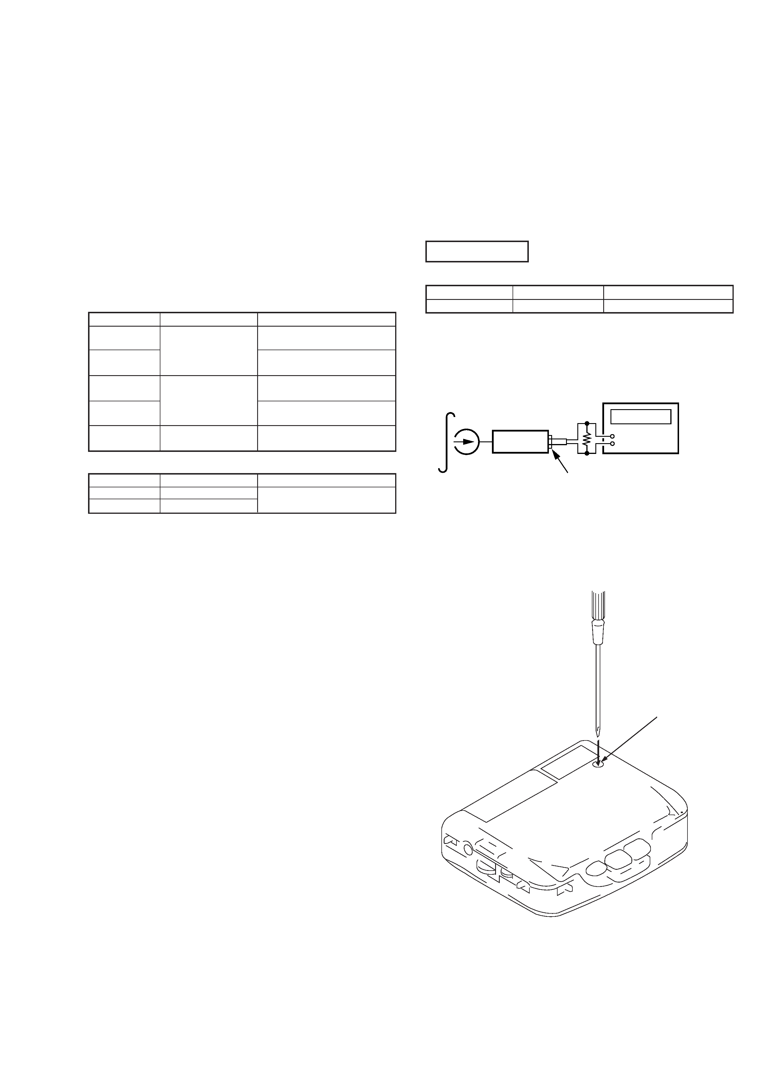
Tape Speed Adjustment
Tape SpeedAdjustment
Procedure:
Play back WS-48A (tape center part) and adjust RV601 so that the
frequency counter reading becomes 2,985 3,015Hz.
Frequency difference the beginning and the end of the tape should
be within 1.5%.
Adjustment Location :
set
test tape
WS-48A
(3kHz, 0dB)
frequency counter
+
J302 (phones)
16
RV601