1
Model Name Using Similar Mechanism
NEW
Tape Transport Mechanism Type
MF-WMEX9-162
SERVICE MANUAL
Tourist Model
WM-EX9
CASSETTE PLAYER
System
Compact cassette stereo
Frequency response (Dolby NR off)
Playback: 30 - 18,000 Hz
Output
Headphones
2 jack
Load impedance 8 - 300 ohms
Maximum output level
4 mW + 4 mW (32
)
Power requirements
DC 1.5 V
Nickel metal hydride rechargeable
battery NH-14WM (N) (supplied)
One R6 (size AA) batteries
(negative ground)
Battery life (Approx. hours)
Rechargeable NH-14WM
40
fully charged
Sony alkaline LR6 (WM)
60
Rechargeable NH-14WM
100
Sony alkaline LR6 (WM)
used together
Dimensions (w/h/d)
Approx. 77.7
× 108 × 19.6 mm
projecting parts and controls
Mass
Approx. 140 g / Approx. 205 g
incl. Nickel metal hydride rechargeable
battery NH-14WM (N) and a cassette
Supplied accessories
Battery charger BC-7HT (1)
Rechargeable battery NH-14WM (1)
Rechargeable battery case (1)
Dry battery case (1)
Stereo headphones with remote control
MDR-ED132SP + RM-WME21L (1)
Carrying pouch (1)
AC plug adaptor (1)
Design and specifications are subject to change without notice.
SPECIFICATIONS
Dolby noise reduction manufactured under license from Dolby Labo-
ratories Licensing Corporation.
"DOLBY" and the double-D symbol
a are trademarks of Dolby
Laboratories Licensing Corporation.
MICROFILM
Photo: Gold type
Ver 1.0 1998. 10

2
TABLE OF CONTENTS
1. SERVICING NOTE
1-1. Service Mode ...................................................................... 3
1-2. Rotational System ............................................................... 4
2. GENERAL
Location of controls ................................................................. 5
3. DISASSEMBLY
3-1. Cassette Lid Assy ................................................................ 6
3-2. Case ..................................................................................... 6
3-3. Ornament (OPEN) Block Assy ........................................... 7
3-4. SUB Board, LEAF Switch, MAIN Board ........................... 7
3-5. Belt (F1), Motor (F1) (M701) ............................................. 8
4. MECHANICAL ADJUSTMENTS .............................. 9
5. ELECTRICAL ADJUSTMENTS ............................... 9
6. DIAGRAMS
6-1. Block Diagram .................................................................. 10
6-2. Printed Wiring Boards ....................................................... 12
6-3. Schematic Diagram ........................................................... 15
6-4. Pin Description .................................................................. 18
7. EXPLODED VIEWS
7-1. Case Section ...................................................................... 21
7-2. Mechanism Deck Section .................................................. 22
8. ELECTRICAL PARTS LIST ..................................... 23
Flexible Circuit Board Repairing
· Keep the temperature of the soldering iron around 270°C during
repairing.
· Do not touch the soldering iron on the same conductor of the
circuit board (within 3 times).
· Be careful not to apply force on the conductor when soldering
or unsoldering.
Notes on Chip Component Replacement
· Never reuse a disconnected chip component.
· Notice that the minus side of a tantalum capacitor may be dam-
aged by heat.
3
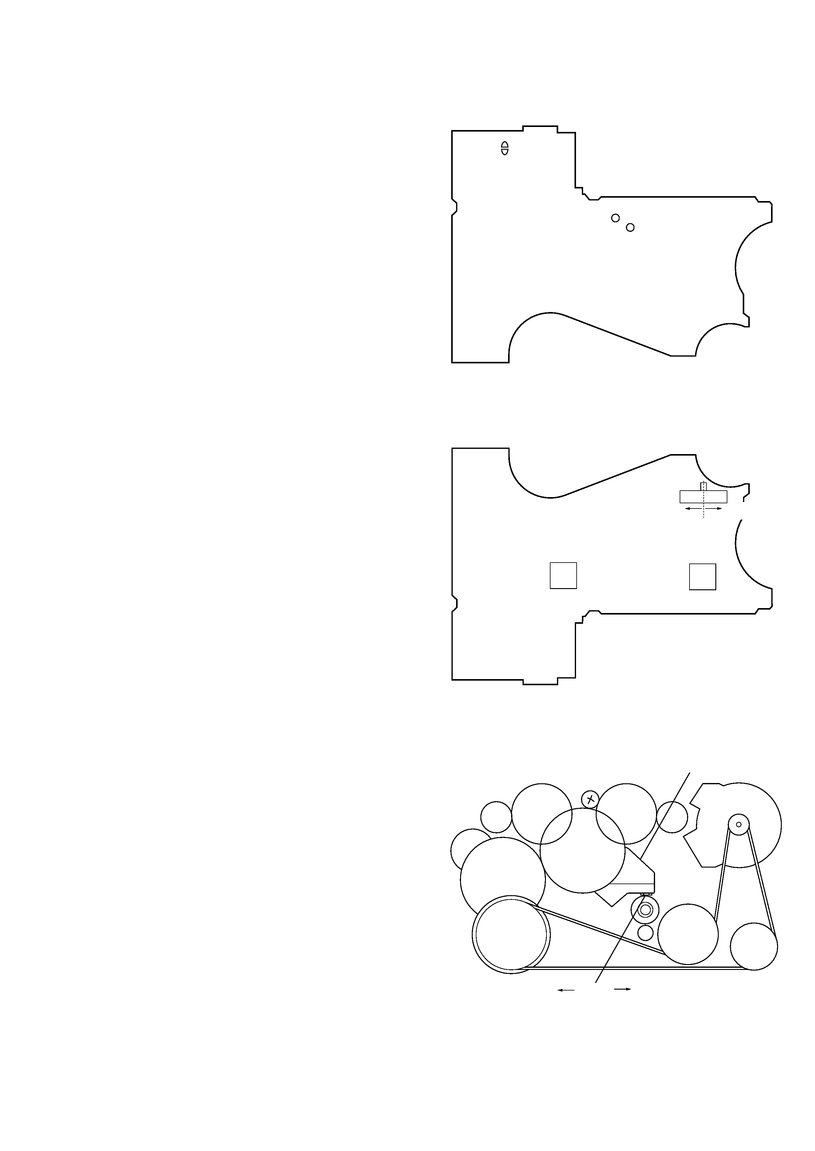
F side
flywheel
slider (NR)
F side
center
R side
SECTION 1
SERVICING NOTE
1-1. SERVICE MODE
Mode to allow the mechanical parts to operate with the audio board
open.
This set uses the photo reflector PH701 to detect the rotation of the
idler gear (A) (S side). PH701 is on the main board and so removal
of the main board does not allow the set to detect the rotation of the
idler gear (A) (S side). This makes motor control impossible which
prevents normal operation.
When repairing the set as energized with the main board removed,
proceed as follows:
1. Setting
1) Remove the case (refer to the Disassembly) and open the main
board.
2) Connect the motor and plunger to the main board with jumper
wire.
The extension jig (1-769-143-11) (one set of ten wires) can be
used for easy connection.
3) Short the TAPE IN switch land (BP701) with solder. Input a
square (or sine) wave of 10 to 100 Hz (at 1.3 V) to both PH IN T
land (TP60) and PH IN S land (TP61) with jumper wire.
4) Supply 1.3 V to the positive and negative terminals of the
battery with a stabilized power supply.
2. Preset state
The set must be in this state before the PLAY, FF and REW modes
can be entered.
1) Make sure that the slider (NR) is in the center position and that
the N/R switch (S701) is in the center position. Make sure that
the reel gear does not rotate by rotating the flywheel on the F
side clockwise. If improper, place the set in the preset state
according to the following instructions:
2) Repeat the step below some times to ensure the above
conditions.
* Pull away the trigger level from the plunger with twezers or other
means. Then rotate the flywheel on the F side clockwise.
3) Turn the stabilized power supply OFF once and then ON.
3. FF/REW mode
1) Check for "2. Preset state" and push the FF switch and the REW
switch.
2) Move the N/R switch (S701) to the movement of the slider to
enter the FF/REW mode.
4. PLAY mode
1) Check for "2. Preset state."
2) Push the
" " switch on the remote commander to move the
lever (SW) toward the R side. With timing to this, move the
N/R switch (S701) to enter the PLAY (R side) mode.
Note 1: If failed, retry from the preset state.
Note 2: The
" ", p, FF and REW switches on the remote
commander should be used whenever possible.
main board (side A)
main board (side B)
mechanism deck
BP701
PH IN T
PH IN S
S701
IC601
IC701
F side
center
R side
4
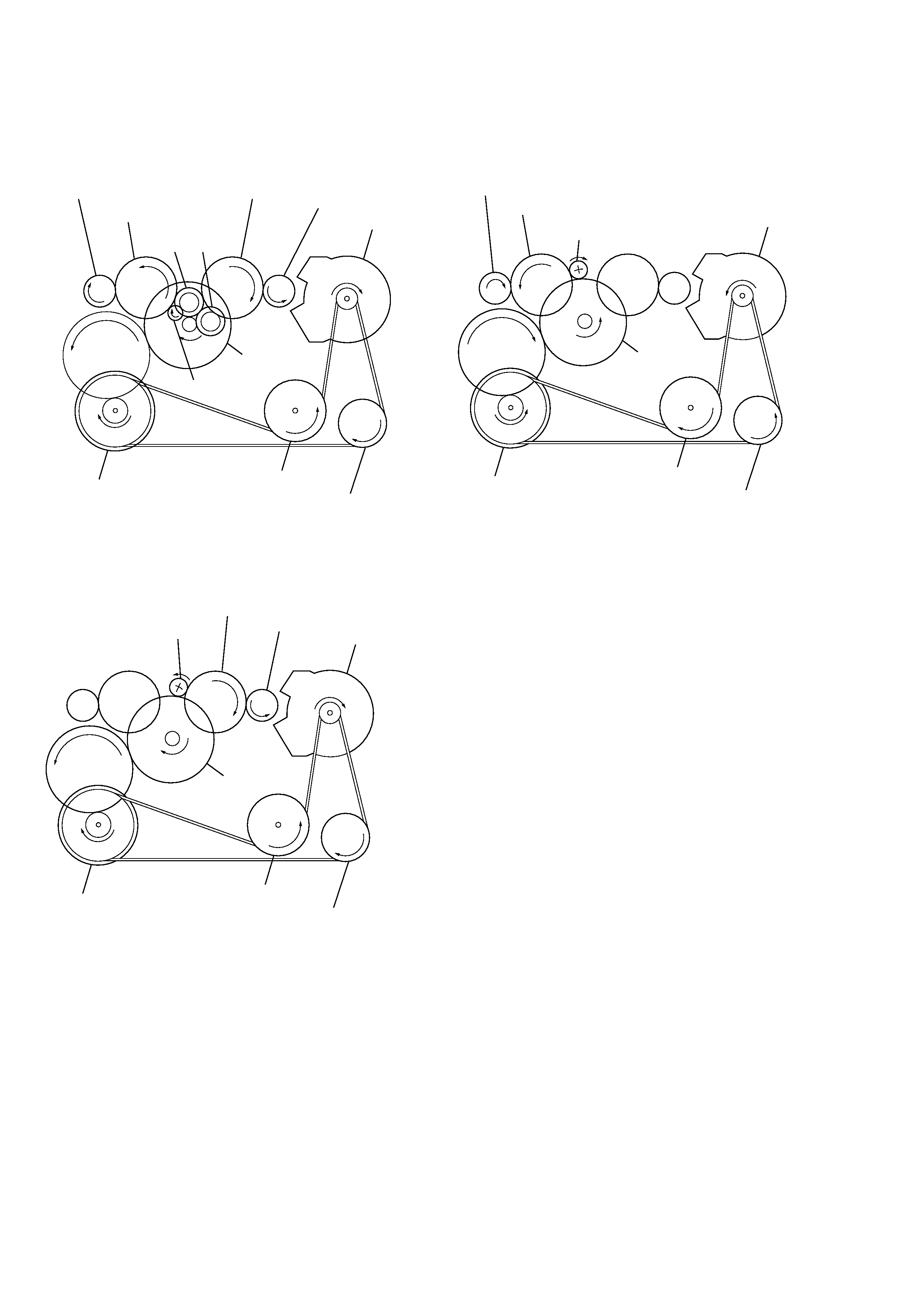
1-2. ROTATIONAL SYSTEM
1. Rotational System of PLAY Mode
2. Rotational System of FF Mode
3. Rotational System of REW Mode
motor pulley
gear (FR)
gear (reel) (S side)
reverse pulley
insert flywheel (R)
insert flywheel (N)
idler gear (A) (S side)
gear (Y)
clutch
assy (F)
motor pulley
reverse pulley
insert flywheel (R)
insert flywheel (N)
gear (reel) (T side)
gear (reel) (S side)
idler gear (A) (T side)
idler gear (A) (S side)
idler gear (B)
gear (Y)
gear (NR)
FWD REV
clutch
assy (F)
motor pulley
gear (FR)
reverse pulley
insert flywheel (R)
insert flywheel (N)
gear (reel) (T side)
idler gear (A) (T side)
gear (Y)
clutch
assy (F)
5
SECTION 2
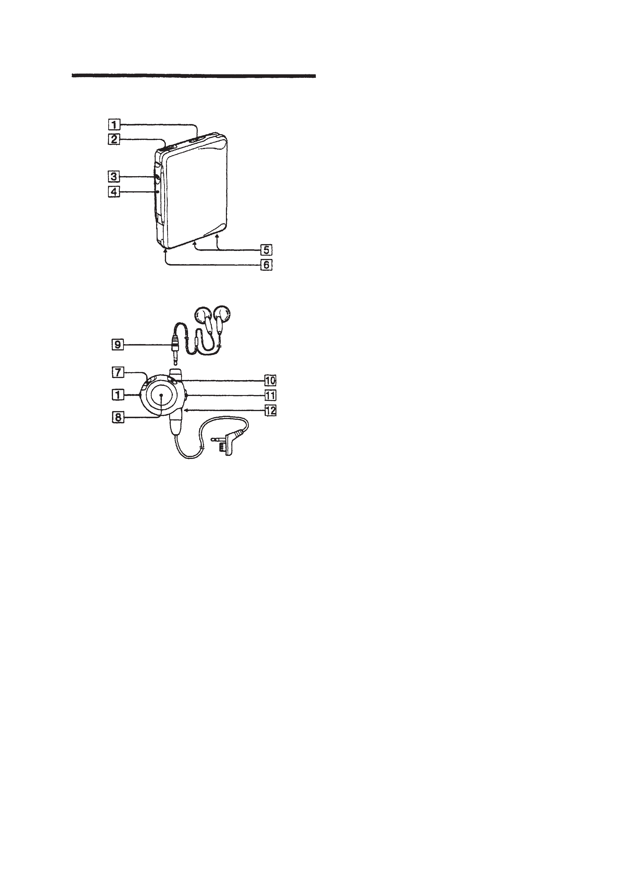
GENERAL
· Main unit
Location of controls
· Stereo headphones with remote control
L (left)
R (right)
1 VOL (volume) knob
2 2 REMOTE (headphone · remote control) jack
3 Operation button
4 OPEN/HOLD/OPERATION switch
5 Dry battery case contact
6 Rechargeable battery compartment
7 HOLD switch
8 Liquid crystal display window
9 Stereo mini-plug
!º MENU button
!¡ Jog lever
!TM Clip