WM-EX7
US Model
Canadian Model
AEP Model
UK Model
E Model
Tourist Model
SERVICE MANUAL
CASSETTE PLAYER
MICROFILM
Manufactured under license from Dolby Laboratories
Licensing Corporation.
"DOLBY" and the double-D symbol a are trademarks
of Dolby Laboratories Licensing Corporation.
SPECIFICATIONS
Model Name Using Similar Mechanism
WM-EX5
Tape Transport Mechanism Type
MT-WMEX7-125
U.S and foreign patents licensed from Dolby
Laboratories Licensing Corporation.
Tape section
Frequency response
(Dolby NR off)
Playback : 30 18,000 Hz
Output
Headphones (REMOTE 2 jack)
Load impedance 8 300
General
Power requirements
1.5 V
One rechargeable battery or one R6 (size AA)
battery
Dimensions (w/h/d)
Approx. 80.2
× 112.2 × 21.45 mm
(31/4
× 41/2 × 7/8 inches), incl.
projecting parts and controls
Mass
Approx. 180 g (6.4 oz.)
Approx. 245 g (8.7 oz) (incl. rechargeable
battery and cassette)
Supplied accessories
Battery case (1)
Stereo earphones with remote control (1)
Battery charger (1)
Rechargeable battery
NC-6WM, 1.2 V, 600 mAh, Ni-Cd (1)
(US, Canadian, and Eupopean model)
NH-14WM, 1.2 V, 1,400 mAh, Ni-MH (1)
(Korean and other countries model)
Rechageable battery carrying case (1)
Carrying pouch (1)
AC plug adaptor (1) (Except for US, Canadian,
European, and Korean model)
Design and specification subject to change without notice.

-- 2 --
TABLE OF CONTENTS
SAFETY-RELATED COMPONENT WARNING!!
COMPONENTS IDENTIFIED BY MARK ! OR DOTTED LINE WITH
MARK ! ON THE SCHEMATIC DIAGRAMS AND IN THE PARTS
LIST ARE CRITICAL TO SAFE OPERATION. REPLACE THESE
COMPONENTS WITH SONY PARTS WHOSE PART NUMBERS
APPEAR AS SHOWN IN THIS MANUAL OR IN SUPPLEMENTS
PUBLISHED BY SONY.
ATTENTION AU COMPOSANT AYANT RAPPORT
À LA SÉCURITÉ!
LES COMPOSANTS IDENTIFÉS PAR UNE MARQUE ! SUR LES
DIAGRAMMES SCHÉMATIQUES ET LA LISTE DES PIÈCES SONT
CRITIQUES POUR LA SÉCURITÉ DE FONCTIONNEMENT. NE
REMPLACER CES COMPOSANTS QUE PAR DES PIÈSES SONY
DONT LES NUMÉROS SONT DONNÉS DANS CE MANUEL OU
DANS LES SUPPÉMENTS PUBLIÉS PAR SONY.
Notes on chip component replacement
· Never reuse a disconnected chip component.
· Notice that the minus side of a tantalum capacitor may be
damaged by heat.
Flexible Circuit Board Repairing
· Keep the temperature of soldering iron around 270°C
during repairing.
· Do not touch the soldering iron on the same conductor of the
circuit board (within 3 times).
· Be careful not to apply force on the conductor when soldering
or unsoldering.
1. GENERAL ·········································································· 3
2. SERVICE NOTE ······························································· 5
3. DISASSEMBLY
3-1. CASSETTE LID ASSY ·················································· 7
3-2. REEL ORNAMENT (B) SLIDER ·································· 7
3-3. CASE ·············································································· 8
3-4. REEL ORNAMENT (B) ASSY ······································ 8
3-5. AUDIO BOARD ····························································· 8
4. MECHANICAL ADJUSTMENT ·································· 9
5. ELECTRICAL ADJUSTMENT ···································· 9
6. DIAGRAMS
6-1. BLOCK DIAGRAM ····················································· 10
6-2. SCHEMATAC DIAGRAM ··········································· 12
6-3. PRINTED WIRING BOARD ······································· 15
6-4. IC BLOCK DIAGRAMS ·············································· 19
6-5. IC PIN FUNCTION ······················································ 22
7. EXPLODED VIEWS
7-1. CABINET BLOCK ······················································· 24
7-2. AUDIO BOARD BLOCK ············································· 25
7-3. MECHANISM DECK BLOCK (MT-WMEX7-125) ··· 26
8. ELECTRICAL PARTS LIST ······································· 27
-- 3 --
SECTION 1
GENERAL
This section is extracted
from instruction manual.
-- 4 --
-- 5 --
SECTION 2
SERVICE NOTE
[Service Mode]
The service mode enables to operate and check the mechanism of
WM-EX7 while the AUDIO board is opened.
1. How to enter the service mode
1)
Remove the cabinet referring to section 3 DISASSEMBLY.
Open the AUDIO board.
2)
Connect the motor and plunger solenoid to the AUDIO board
using jumper wires. The motor and plunger solenoid can be
easily connected when the extension jig (1-769-143-11) (10
cables are bound as a jig.)
3)
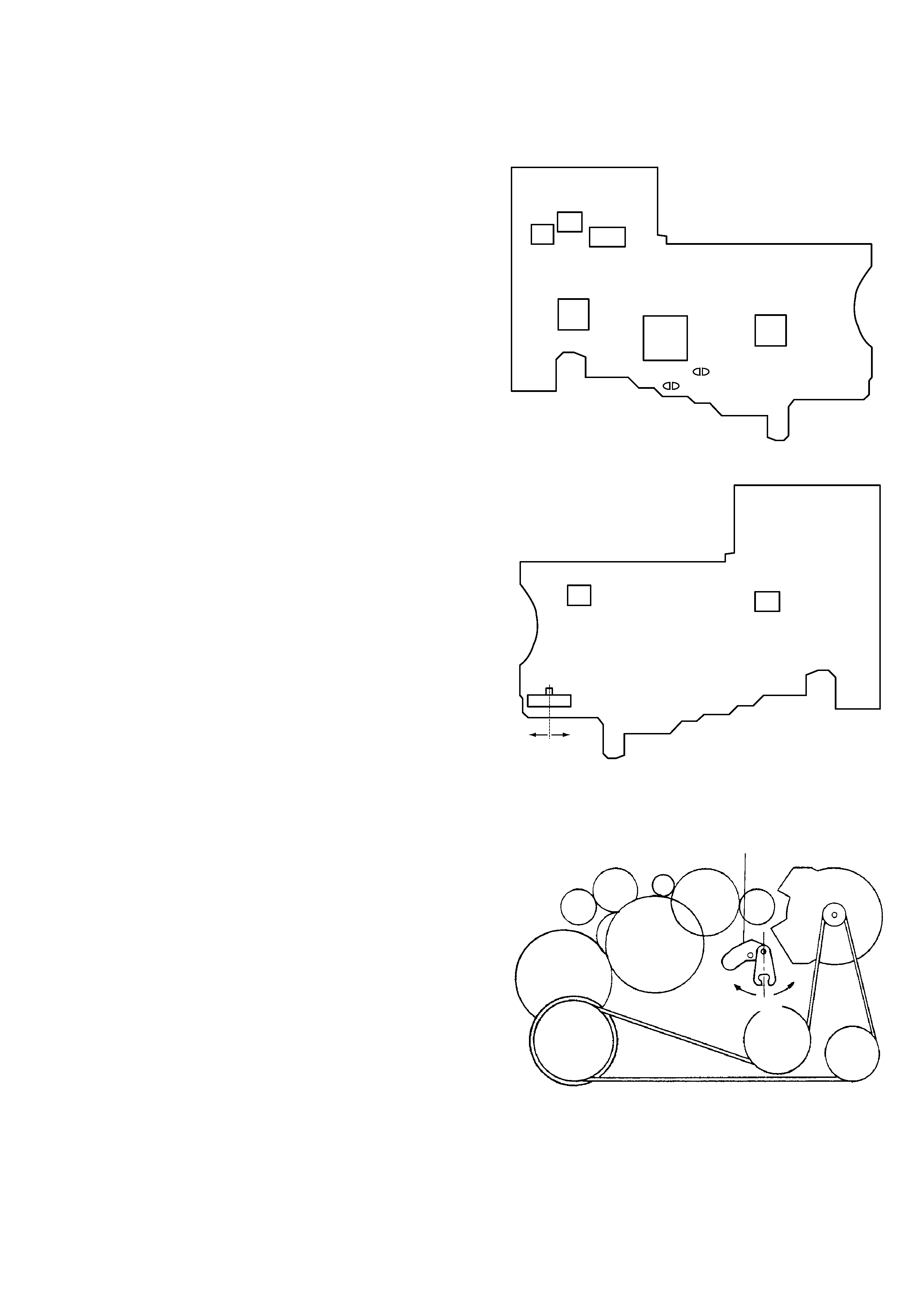
Short the service mode land (BP701) and the holder land
(BP702) as shown using soldering.
4)
Connect DC 1.3 V from a regulated power supply to the ` and
' terminals of battery.
5)
Remove soldering from the service mode land (BP701).
2. PRE-SET status
The PLAY, FF and REW mode can be entered only from the PRE-
SET status.
1)
Check that the lever (SW) is in the center position, and the F/R
switch (S704) is also I the center position. When these switches
are not in the center position, set them to the center (pre-set)
position as follows.
2)
Find the position in which the lever (SW) is set (either F or R
position). Move the F/R switch (S704) into the position in
which the lever (SW) is set.
(3) The lever (SW) can be moved by turning OFF the main power
of the regulated power supply once then back ON. Move the
F/R switch (S704) to the center position in synchronism with
this timing.
3. FF, REW modes
1)
After confirming the "2. PRE-SET status", press the FF switch
or the REW switch.
4. PLAY mode
1)
Confirm the "2. PRE-SET status".
2)
When the 9( switch of the remote control is pressed, the
lever (SW moves once to the R side then moves to the F side.
Move the F/W switch (S704) to the R side in synchronism with
the motion of the lever (SW). It enables the system to enter
into the PLAY (R side) mode.
Note 1: When you fail to enter the PLAY mode, re-start from step
1) PRE-SET status.
Note 2: When you operate 9(, p, FF, REW switch, use these
switches of the remote control unit as much as possible.
[AUDIO board]
-- Side A --
-- Side B --
[Lever (SW)]
IC601
IC701
BP701
IC301
IC305
IC303
IC302
BP702
IC801
F side
S704
IC304
Center
R side
Lever (SW)
Center
R side
F side