WM-EX170/EX172
Canadian Model
WM-EX170
AEP Model
E Model
WM-EX170/172
SERVICE MANUAL
CASSETTE PLAYER
MICROFILM
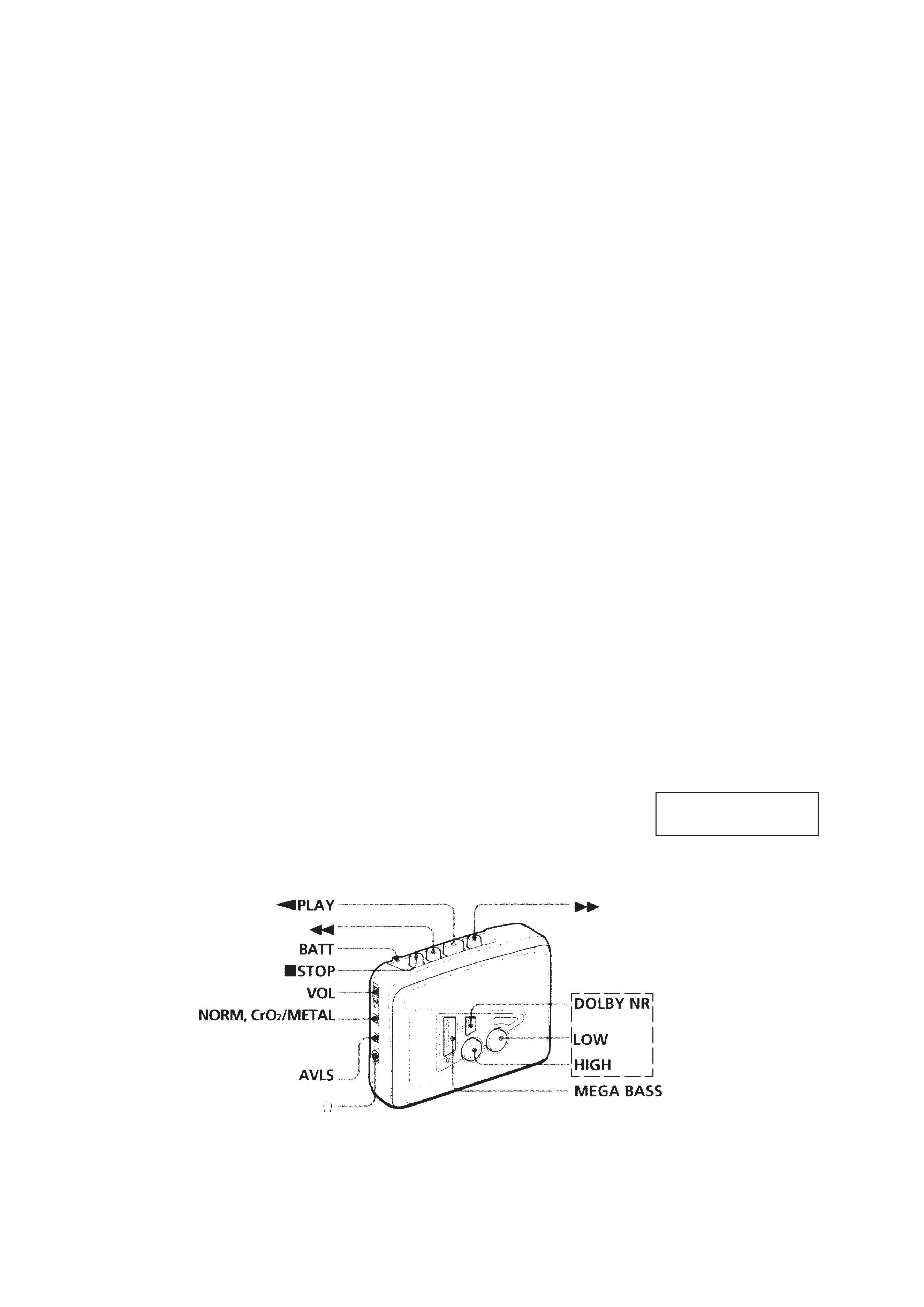
SPECIFICATIONS
Model Name Using Similar Mechanism
NEW
Tape Transport Mechanism Type
MT-WMEX170-114
Manufactured under license from Dolby Laboratories
Licensing Corporation.
"DOLBY" and the double-D symbol a are trademarks
of Dolby Laboratories Licensing Corporation.
· Power requirements
3V DC batteries R6 (AA)
× 2 / External DC 3V power sources
· Dimensions
88.5
× 111.5 × 37.6 mm
(3 1/2
× 4 1/2 × 1 1/2 inches) (w / h/ d) incl. projecting parts and controls
· Mass
EX170 : Approx. 125 g (4.5 oz) / Approx. 185 g (6.6 oz) incl.
batteries and a cassette
EX172 : Approx. 130 g (4.6 oz) / Approx. 190g (6.8 oz) incl.
batteries and a cassette
· Supplied accessories
Stereo headphones or Stereo earphones (1) / Belt clip (1)
Design and specifications are subject to change without notice.
Photo : WM-EX172
-- 2 --
TABLE OF CONTENTS
Flexible Circuit Board Repairing
·
Keep the temperature of the soldering iron aroud 270° C during
repairing.
·
Do not touch the soldering iron on the same conductor of the
circuit board (within 3 times).
·
Be careful not to apply force on the conductor when soldering
or unsoldering.
Notes on chip component replacement
·
Never reuse a disconnected chip component.
·
Notice that the minus side of a tantalum capacitor may be
damaged by heat.
SECTION 1
GENERAL
1.
GENERAL ······································································ 2
2.
DISASSEMBLY
2-1.
Cabinet (Front) Assy ·························································· 3
2-2.
Main Board ········································································· 4
2-3.
Cassette Lid ········································································ 4
2-4.
Mechanism Deck ································································ 5
2-5.
Belt, Motor (Reel/Capstan) ················································ 5
3.
MECHANICAL ADJUSTMENT ······························ 6
4.
ELECTRICAL ADJUSTMENT ································ 6
5.
DIAGRAMS
5-1.
Block Diagram ··································································· 7
5-2.
Printed Wiring Board (EX170 Model) ······························· 9
5-3.
Schematic Diagram (EX170 Model) ································ 11
5-4.
Printed Wiring Board (EX172 Model) ····························· 13
5-5.
Schematic Diagram (EX172 Model) ································ 15
5-6.
IC Block Diagrams ··························································· 17
6.
EXPLODED VIEWS
6-1.
Cabinet Section ································································· 18
6-2.
Main Board Section ·························································· 19
6-3.
Mechanism Section-1 (MT-WMEX170-114) ·················· 20
6-4.
Mechanism Section-2 (MT-WMEX170-114) ·················· 21
7.
ELECTRICAL PARTS LIST ··································· 22
This section is extracted
from instruction manual.
EX172 MODEL
-- 3 --
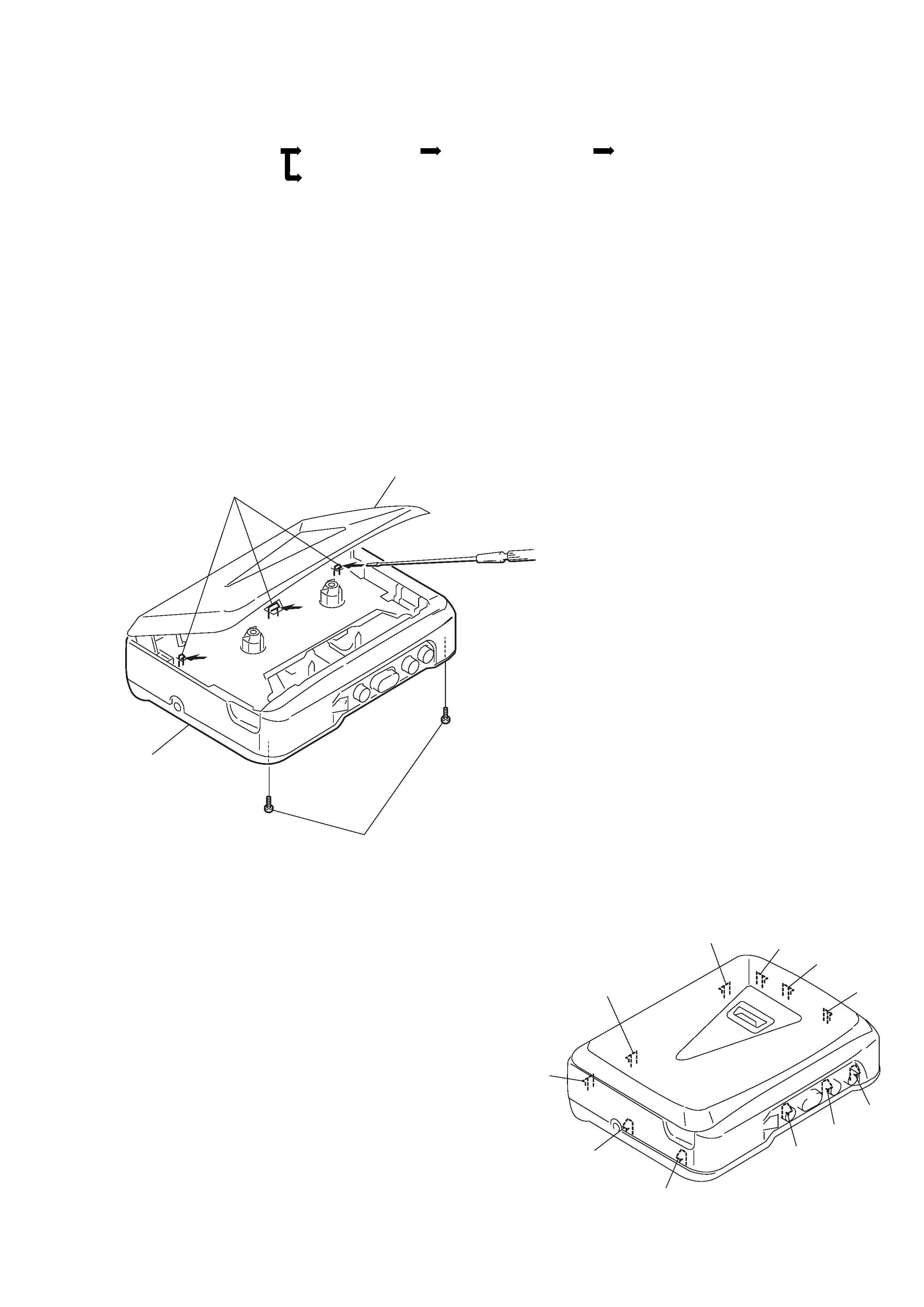
Cassette, lid
Cabinet (front) assy
A
1 Two screws
[Screw (B1.7
× 9), tapping]
SECTION 2
DISASSEMBLY
Note :
Follow the disassembly procedure in the numerical order given.
2-1. CABINET (FRONT) ASSY
2 Insert the precision screwdriver
(1.4 mm flat-blade) into the slit
at claw A and release the claw.
3 Remove the cabinet (front) assy.
(Release all claws B to L in
alphabetical order.)
· This set can be disassembled in the order shown below.
2-1. CABINET (FRONT) ASSY
2-2. MAIN BOARD
2-3. CASSETTE LID
2-4. MECHANISM DECK
2-5. BELT, MOTOR (REEL/CAPSTAN)
B
L
K
C
D
E
F
G
H
I
J
-- 4 --
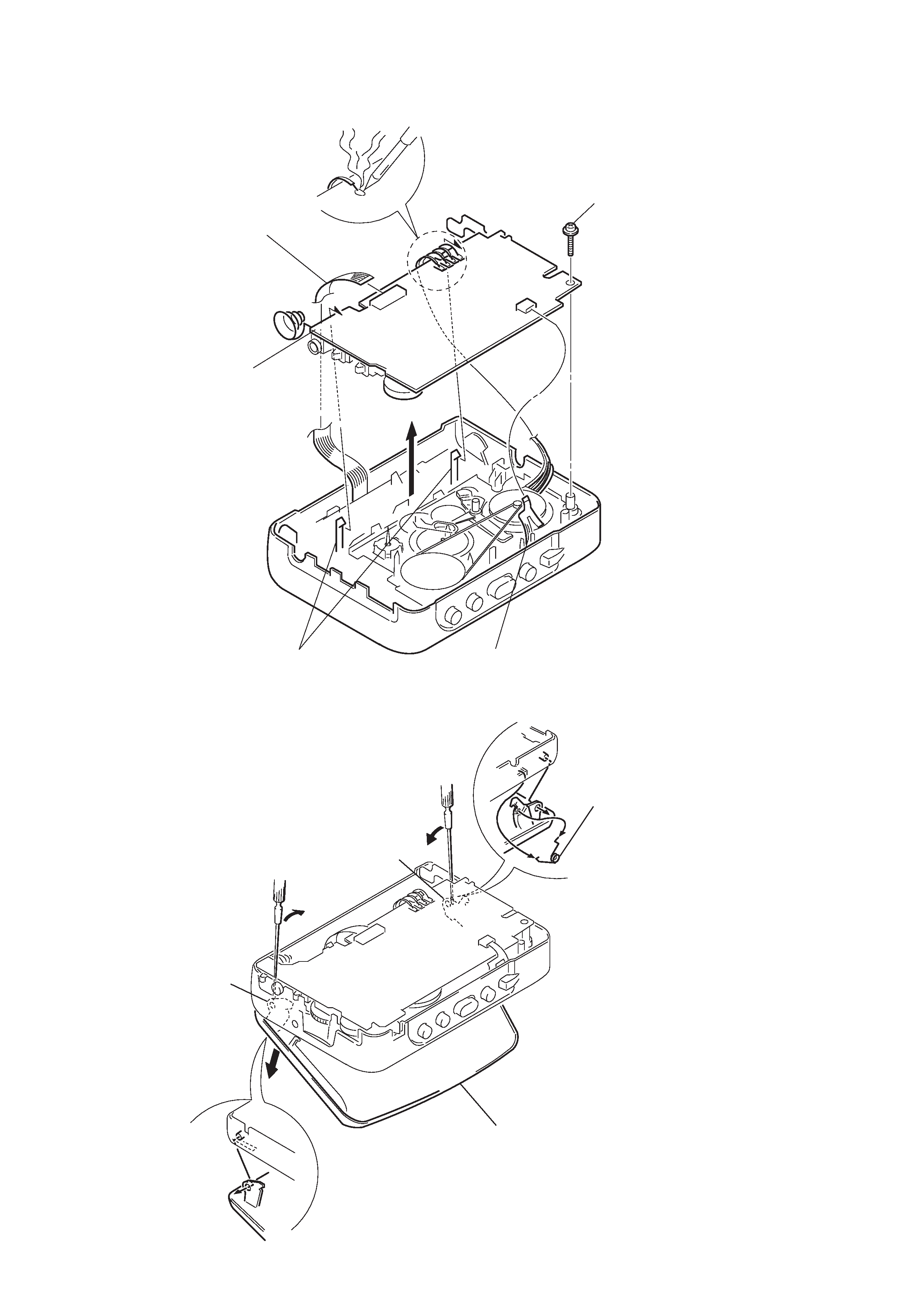
5 Spring (torsion)
B
A
1 Open the cassette lid.
4 Cassette lid.
2-2. MAIN BOARD
2-3. CASSETTE LID
2 Insert a precision screwdriver
(1.4 mm flat-blade) vertically
into portion A to release the
hinge plate.
3 Portion B to release the
hinge plate.
1 Head flexible board (CN301)
5 Two claws
6 MAIN board
3 Remove the four solders.
4 Screw (M1.4), toothed lock (WH)
2 Flexible board (CN302)
-- 5 --
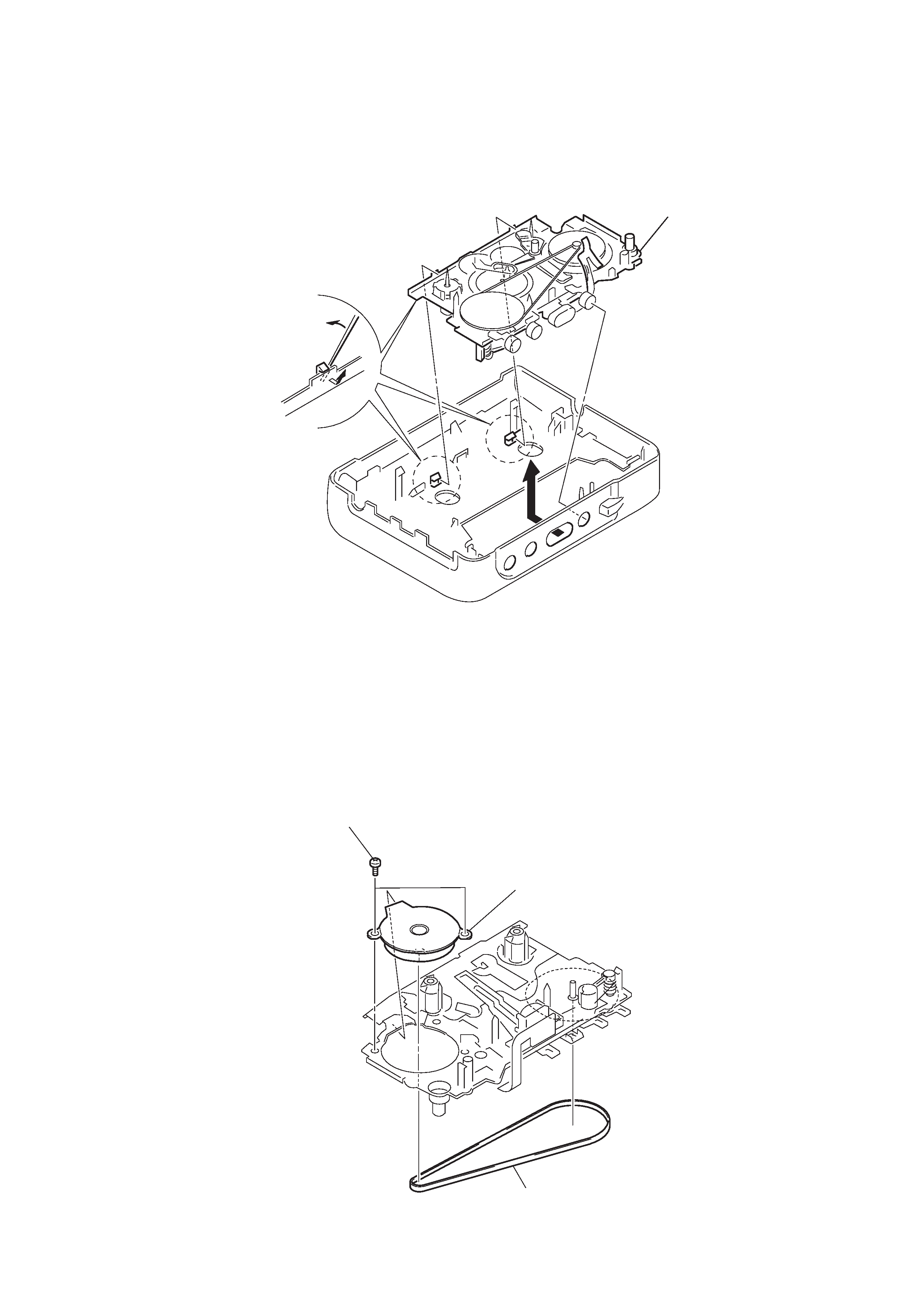
2 Two screw [screw (M1.4), special head]
3 Motor (reel/capstan)
1 Belt
2-4. MECHANISM DECK
2-5. BELT, MOTOR (REEL/CAPSTAN)
1 Insert the precision screwdriver
(1.4 mm flat-blabe) in to the slit
and release two claws.
2 Remove the mechanism deck
in the direction of the arrow.