SERVICE MANUAL
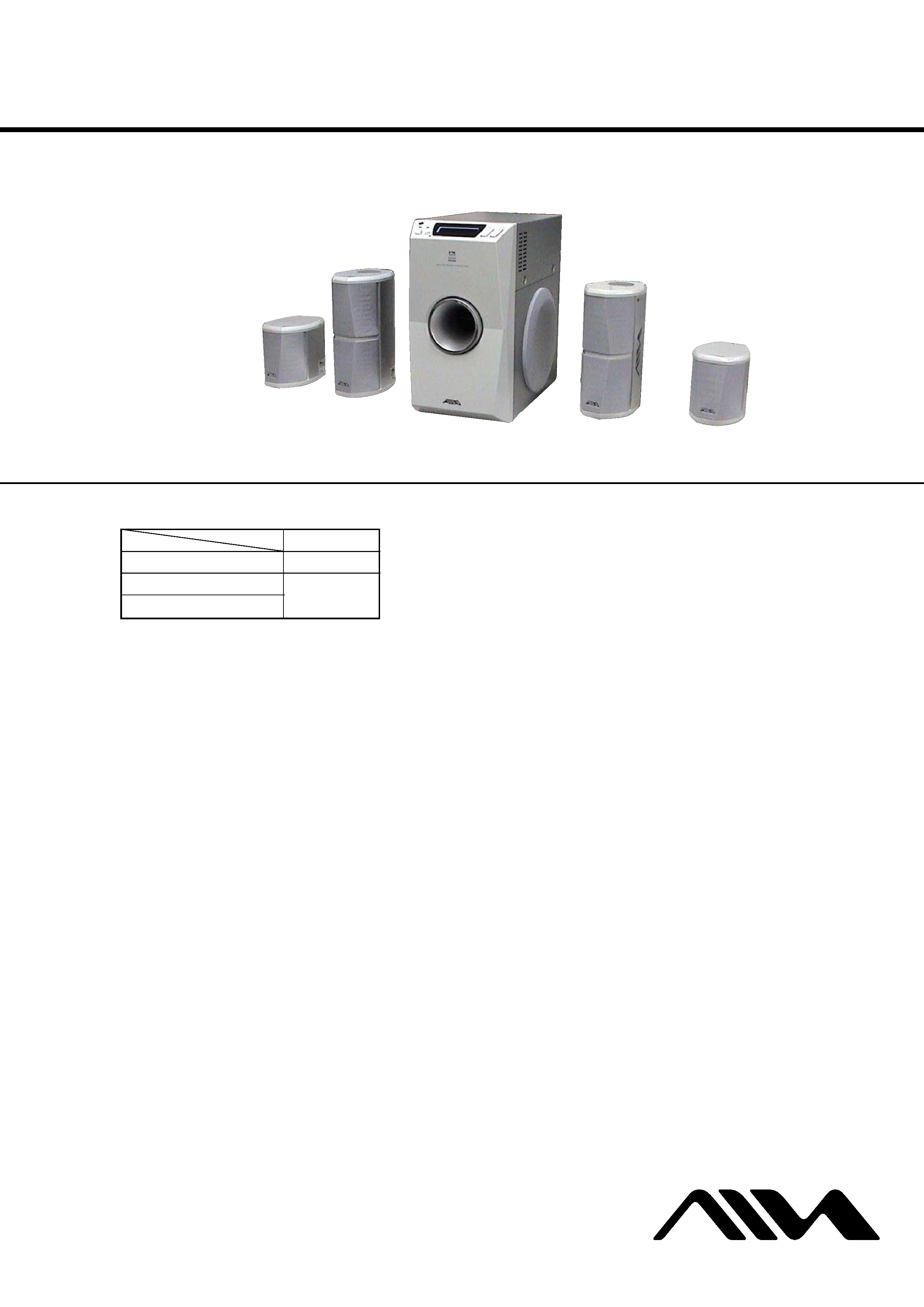
USB ACTIVE SPEAKER SYSTEM
US Model
AEP Model
UK Model
E Model
SPECIFICATIONS
SS-US501/SW-US501/UZ-US501
Ver 1.0 2004.01
9-877-530-01
Sony Corporation
2004A05-1
Aiwa Original Products
C
2004.01
Published by Sony Engineering Corporation
For the U.S.A. model
AUDIO POWER SPECIFICATIONS
POWER OUTPUT AND TOTAL
HARMONIC DISTORTION:
With 4 ohms loads subwoofer driven, from
20 - 200 Hz; rated 20 watts minimum RMS
power, with no more than 0.8% total
harmonic distortion from 250 milliwatts to
rated output.
SW-US501 (Subwoofer)
Max. output
Subwoofer:
30 W (4 ohms)
Front:
14 W + 14 W (8 ohms)
Dual center*:
14 W (4 ohms + 4 ohms)
Surround*:
14 W + 14 W (8 ohms)
* Depending on the sound field settings and the
source, there may be no sound output.
Speaker system Bass reflex type
Speaker unit
130 mm (5 1/8 in.) dia.
cone type
Dimensions (approx.)
160
× 300 × 300 mm
(6 3/8
× 11 7/8 × 11 7/8 in.)
(w/h/d, not including the
projecting parts)
Mass (approx.)
5.8 kg (12 lb 13 oz)
SS-US501 (Front/Center speakers)
Speaker system Front:
Closed box type
Center: Uni directional type
Speaker unit
Front:
58 mm (2 3/8 in.) dia.
cone type
Center: 48 mm (1 15/16 in.) dia.
cone type
Rated impedance
Front:
8 ohms
Center: 4 ohms + 4 ohms
Dimensions (approx.)
85
× 200 × 125 mm
(3 3/8
× 7 7/8 × 5 in.)
(w/h/d, not including the
projecting parts)
Mass (approx.)
650g (1 lb 7 oz)
× 2
Length of cable 3 m (9 ft.)
SS-US501 (Surround speakers)
Speaker system Closed box type
Speaker unit
58 mm (2 3/8 in.) dia. cone type
Rated impedance 8 ohms
Dimensions (approx.)
85
× 106 × 125 mm
(3 3/8
× 4 1/4 × 5 in.)
(w/h/d, not including the
projecting parts)
Mass (approx.)
350g (13 oz)
× 2
Length of cable 8 m (24 ft.)
General
Power requirements
U.S.A. model:
120 V AC, 60 Hz
Other model:
220-240 V AC,
50/60 Hz
Power consumption
U.S.A. model:
75 W
1.2 W
(at the Power Saving Mode)
Other model:
75 W
0.3 W
(at the Power Saving Mode)
Operating temperature
5ßC to 35ßC
Operating humidity
5 % to 90 %
Supplied accessories
Design and specifications are subject to change
without notice.
USB cable 1.8 m
(5.9 ft.) (1)
Remote commander
(remote) RM-Z7S101 (1)
CD-ROM WinDVD (1)
Operating Instructions
(this book) (1)
· UZ-US501 consists of the following models respectively.
UZ-US501
Subwoofer
SW-US501
Front/Center Speakers
SS-US501
Surround Speakers
This system incorporates Dolby* Digital and Pro Logic Surround and
the DTS** Digital Surround System.
* Manufactured under license from Dolby Laboratories.
Dolby , Pro Logic , and the double-D symbol are trademarks of
Dolby Laboratories.
** Manufactured under license from Digital Theater Systems, Inc. DTS and
DTS Digital Surround are registered trademarks of Digital Theater Systems, Inc.
SS-US501
(SURROUND)
SS-US501
(FRONT/CENTER)
SW-US501
(SUBWOOFER)
SS-US501
(FRONT/CENTER)
SS-US501
(SURROUND)
2
SS-US501/SW-US501/UZ-US501
SAFETY-RELATED COMPONENT WARNING!!
COMPONENTS IDENTIFIED BY MARK 0 OR DOTTED
LINE WITH MARK 0 ON THE SCHEMATIC DIAGRAMS
AND IN THE PARTS LIST ARE CRITICAL TO SAFE
OPERATION. REPLACE THESE COMPONENTS WITH
SONY PARTS WHOSE PART NUMBERS APPEAR AS
SHOWN IN THIS MANUAL OR IN SUPPLEMENTS PUB-
LISHED BY SONY.
Notes on chip component replacement
·Never reuse a disconnected chip component.
· Notice that the minus side of a tantalum capacitor may be dam-
aged by heat.
UNLEADED SOLDER
Boards requiring use of unleaded solder are printed with the lead-
free mark (LF) indicating the solder contains no lead.
(Caution: Some printed circuit boards may not come printed with
the lead free mark due to their particular size)
: LEAD FREE MARK
Unleaded solder has the following characteristics.
· Unleaded solder melts at a temperature about 40 °C higher than
ordinary solder.
Ordinary soldering irons can be used but the iron tip has to be
applied to the solder joint for a slightly longer time.
Soldering irons using a temperature regulator should be set to
about 350 °C.
Caution: The printed pattern (copper foil) may peel away if the
heated tip is applied for too long, so be careful!
· Strong viscosity
Unleaded solder is more viscou-s (sticky, less prone to flow)
than ordinary solder so use caution not to let solder bridges oc-
cur such as on IC pins, etc.
· Usable with ordinary solder
It is best to use only unleaded solder but unleaded solder may
also be added to ordinary solder.
SAFETY CHECK-OUT
After correcting the original service problem, perform the follow-
ing safety check before releasing the set to the customer:
Check the antenna terminals, metal trim, "metallized" knobs,
screws, and all other exposed metal parts for AC leakage.
Check leakage as described below.
LEAKAGE TEST
The AC leakage from any exposed metal part to earth ground and
from all exposed metal parts to any exposed metal part having a
return to chassis, must not exceed 0.5 mA (500 microamperes.).
Leakage current can be measured by any one of three methods.
1. A commercial leakage tester, such as the Simpson 229 or RCA
WT-540A. Follow the manufacturers' instructions to use these
instruments.
2. A battery-operated AC milliammeter. The Data Precision 245
digital multimeter is suitable for this job.
3. Measuring the voltage drop across a resistor by means of a
VOM or battery-operated AC voltmeter. The "limit" indica-
tion is 0.75 V, so analog meters must have an accurate low-
voltage scale. The Simpson 250 and Sanwa SH-63Trd are ex-
amples of a passive VOM that is suitable. Nearly all battery
operated digital multimeters that have a 2 V AC range are suit-
able. (See Fig. A)
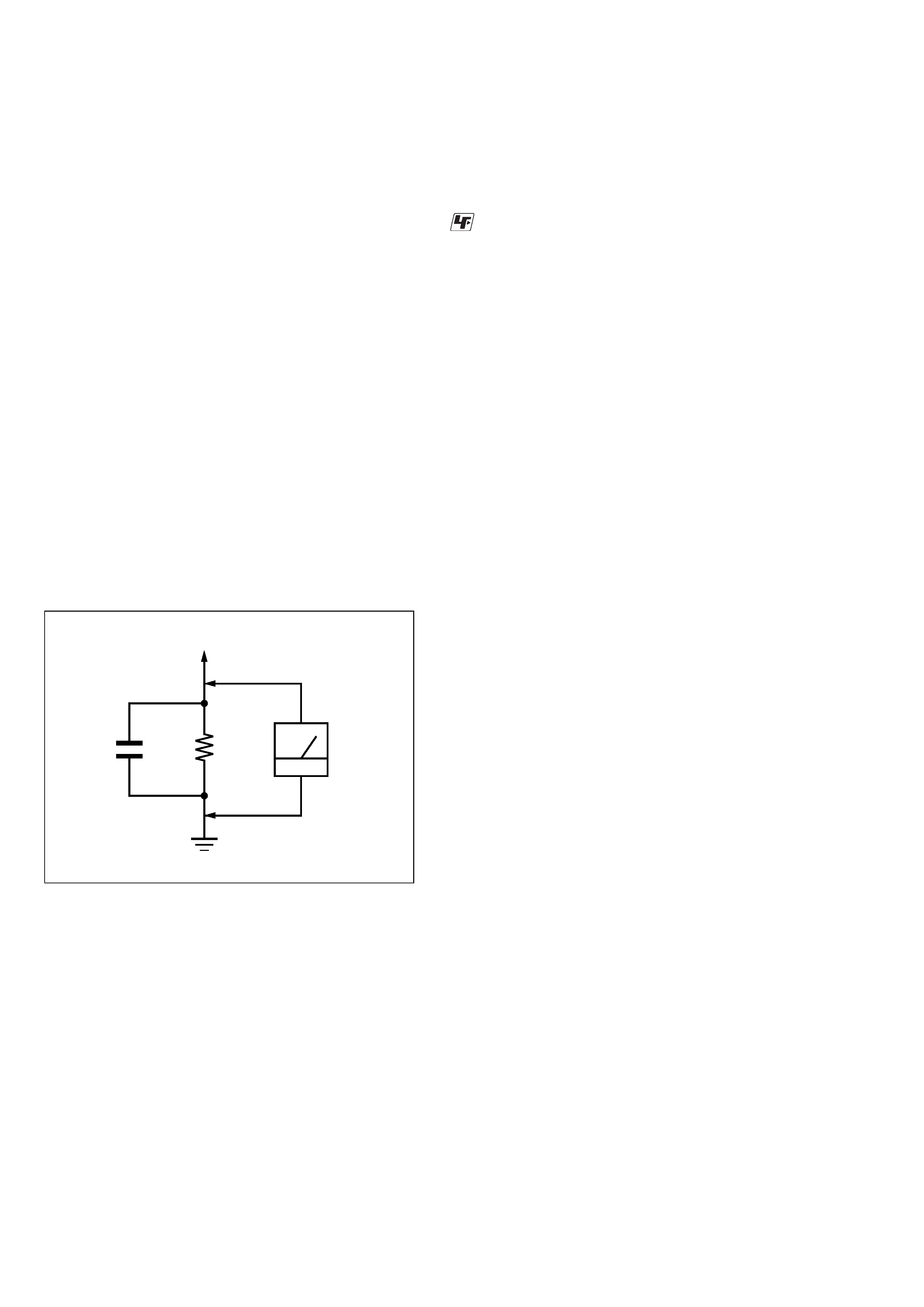
Fig. A.
Using an AC voltmeter to check AC leakage.
1.5 k
0.15 µF
AC
voltmeter
(0.75 V)
To Exposed Metal
Parts on Set
Earth Ground
3
SS-US501/SW-US501/UZ-US501
TABLE OF CONTENTS
1.
SERVICING NOTE .................................................
3
2.
GENERAL ..................................................................
4
3.
DISASSEMBLY
3-1. Disassembly Flow ...........................................................
6
3-2. Top Chassis .....................................................................
6
3-3. DIGITAL Board ..............................................................
7
3-4. Front Cabinet Section .....................................................
7
4.
TEST MODE .............................................................
8
5.
DIAGRAMS
5-1. Block Diagram MAIN Section ................................
9
5-2. Block Diagram
DISPLAY/POWER SUPPLY Section ...................... 10
5-3. Note for Printed Wiring Boards and
Schematic Diagrams ....................................................... 11
5-4. Printed Wiring Board DIGITAL Board ................... 12
5-4. Schematic Diagram DIGITAL Board (1/5) ............. 13
5-5. Schematic Diagram DIGITAL Board (2/5) ............. 14
5-6. Schematic Diagram DIGITAL Board (3/5) ............. 15
5-7. Schematic Diagram DIGITAL Board (4/5) ............. 16
5-9. Schematic Diagram DIGITAL Board (5/5) ............. 17
5-10. Printed Wiring Board DISPLAY Board .................. 18
5-11. Schematic Diagram DISPLAY Board ..................... 19
5-12. Printed Wiring Board AMP Board .......................... 20
5-13. Schematic Diagram AMP Board ............................. 21
5-14. Printed Wiring Board
SUB Board (Except US model) ................................ 22
5-15. Schematic Diagram
SUB Board (Except US model) ................................ 22
6.
EXPLODED VIEWS
6-1. Overall Section ................................................................ 33
6-2. Front Cabinet Section ..................................................... 34
6-3. Main Section ................................................................... 35
6-4. Rear Chassis Section ....................................................... 36
6-5. Front/Surround Speaker Section ..................................... 37
7.
ELECTRICAL PARTS LIST .............................. 38
FRONT
CENTER
SURROUND
RL
USB
OPTICAL IN
ANALOG IN
SPEAKER
RL
Rear View
PART No.
SECTION 1
SERVICING NOTE
· MODEL IDENTIFICATION
MODEL
PART No.
UK model (WHITE)
4-254-202-0[]
Singapore model
4-254-615-0[]
Hong Kong model
4-254-915-0[]
AEP model (BLACK)
4-255-268-0[]
UK model (BLACK)
4-255-269-0[]
US model
4-255-394-0[]
AEP model (WHITE)
4-255-469-0[]
4
SS-US501/SW-US501/UZ-US501
SECTION 2
GENERAL
This section is extracted from
instruction manual.
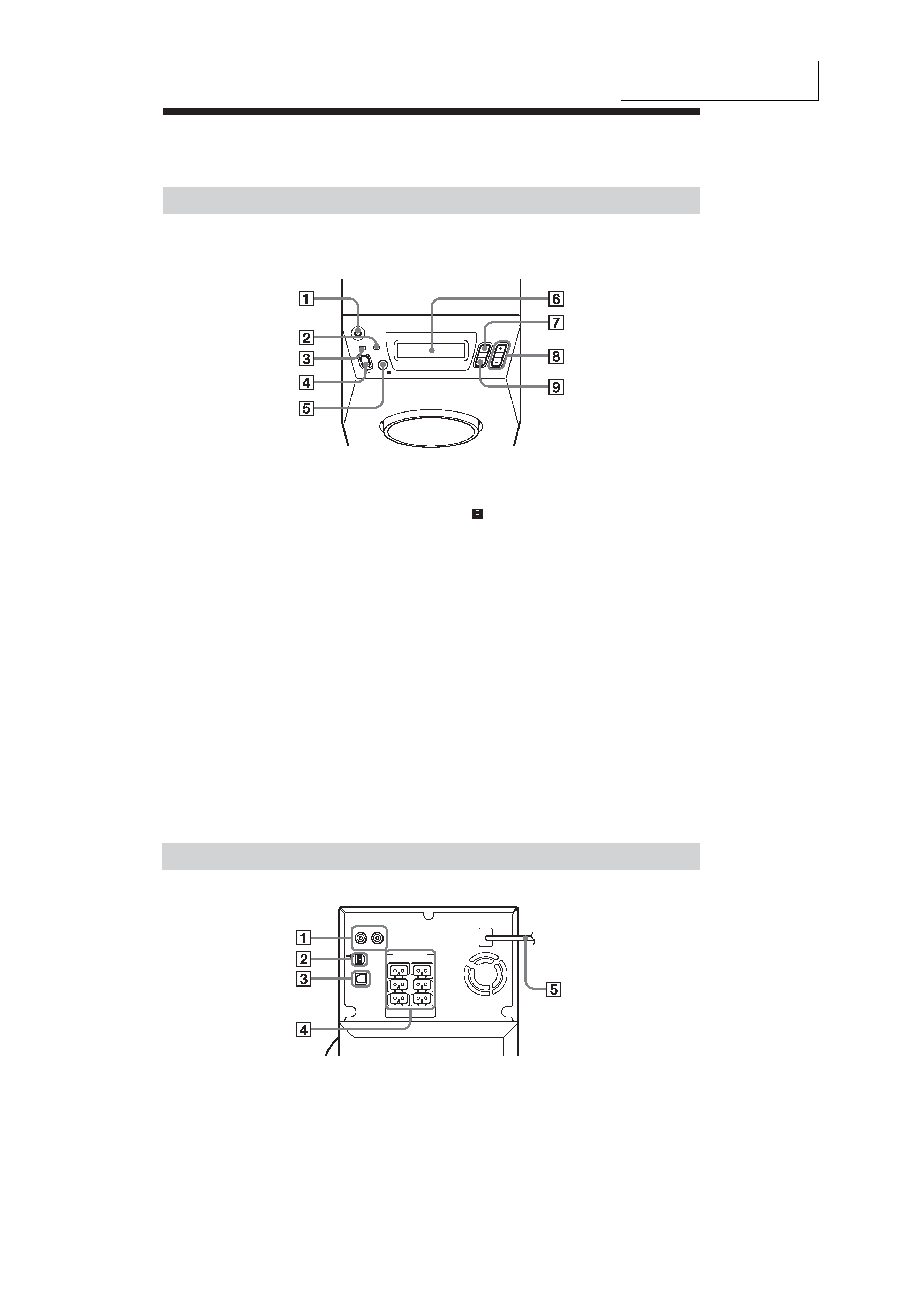
Index to Parts and Controls
Subwoofer (Front Panel)
PHONES
VOLUME
AUTO POWER
INPUT
S-MODE
1 HEADPHONE jack
Connect headphones here.
2 AUTO POWER indicator
When the system is in the AUTO
POWER ON mode, the indicator lights
up green.
3 ?/1 (POWER) indicator
When turned on, lights up green.
When turned off, lights up red (STAND-
BY MODE).
4 ?/1 (POWER)
Turns on and off the power of the
system.
5
(remote sensor)
Receives the remote control signals.
6 Display
Indicates the speaker setting, input
signal, sound field mode, etc.
7 INPUT
Select the input signal.
8 VOLUME +/-
Adjust the volume and select settings.
9 S-MODE
Adjust the sound field mode and select
settings.
R
SPEAKER
L
FRONT
CENTER
SURROUND
ANALOG IN
USB
R
L
OPTICAL IN
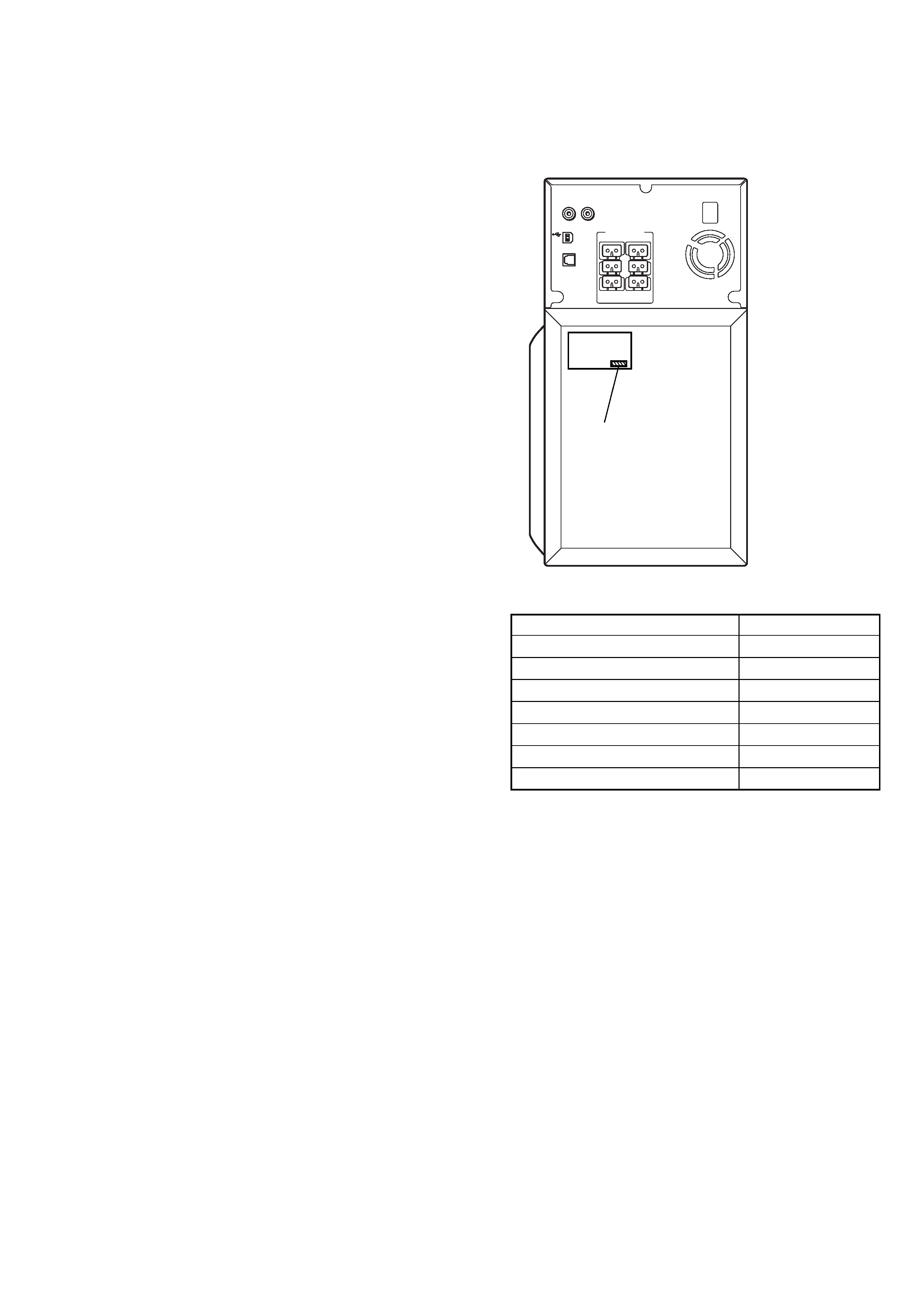
1 ANALOG IN (L/R) jacks
Connect to the audio output of a TV,
VCR, etc.
2 USB jack
Connect to the computer.
Subwoofer (Rear Panel)
3 OPTICAL IN jack
Connect to the DIGITAL OUT
(OPTICAL IN) jack of a DVD player,
etc.
4 SPEAKER jacks
Connect to the supplied satellite
speakers.
5 AC power cord (mains lead)
5
SS-US501/SW-US501/UZ-US501
WOOFER
SELECT
SELECT
VOLUME
INPUT
CENTER
SURR
SET UP
TEST TONE
S-MODE
SHIFT
MUTING
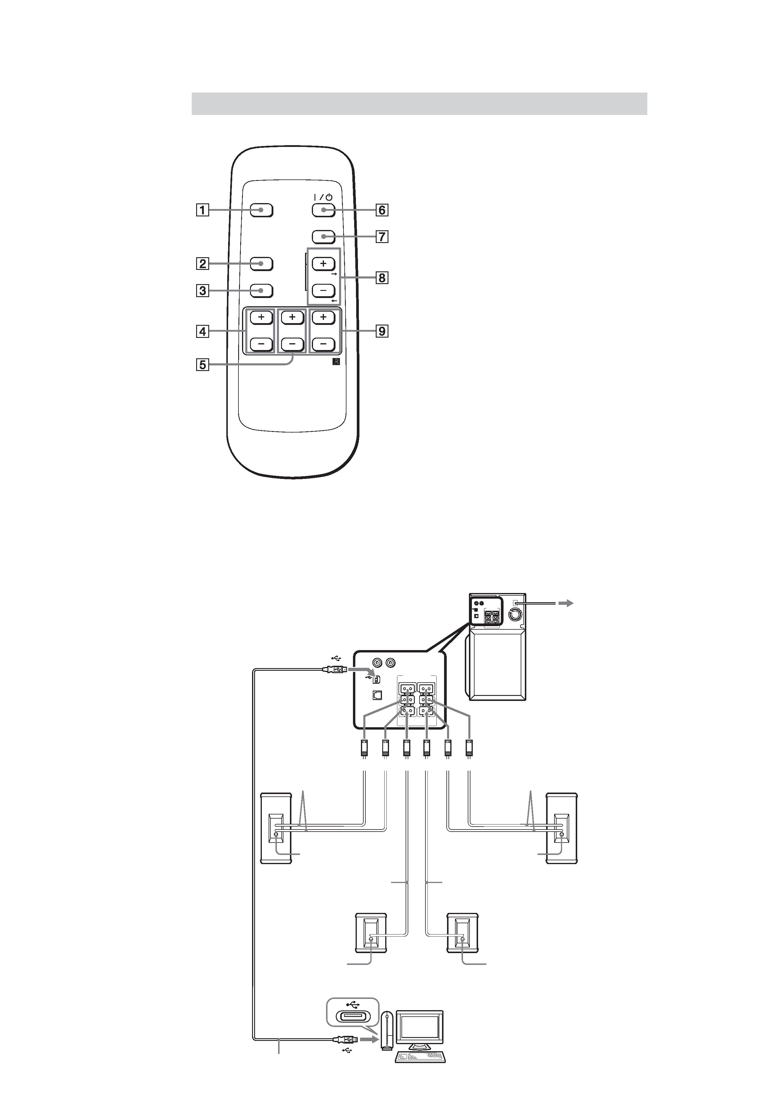
Remote
1 MUTING, TEST TONE
Mutes the sound.
Pressing this button while pressing
SHIFT will sound the test tone.
2 S-MODE, SET UP
Selects the sound field mode.
Pressing this button while pressing
SHIFT will select the system menu.
3 SHIFT
Switches the function of the buttons on
the remote.
4 SURR +/-
Adjust the surround speakers volume.
5 CENTER +/-
Adjust the center speaker volume.
6 ?/1 (POWER)
Turns on and off the system.
7 INPUT
Selects the input signal.
8 VOLUME +/-, SELECT C/c
Makes the speaker settings or adjusts the
volume of the system.
Pressing this button while pressing
SHIFT will set the system setup
parameters.
9 WOOFER +/-
Adjust the subwoofer volume.
Connection
R
SPEAKER
L
FRONT
CENTER
SURROUND
ANALOG IN
USB
R
L
OPTICAL IN
R
SPEAKER
L
FRONT
CENTER
SURROUND
ANALOG IN
USB
R
L
OPTICAL IN
To wall outlet
(mains)
Front /Center
speaker (R)
Front/Center
speaker (L)
Subwoofer (this system)
To USB port
Speaker cords
Speaker cords
Front (R)
Center (R)
Front (L)
Center (L)
Hole for attaching the floor
stand (not supplied)
Hole for attaching the floor
stand (not supplied)
Speaker cord
Speaker cord
Surround speaker (R)
Surround speaker (L)
Hole for attaching
the floor stand
(not supplied)
Hole for attaching
the floor stand
(not supplied)
To USB port
USB cable (supplied)
To your computer
Red
Green
White
Gray Blue
Purple
A