MICROFILM
SERVICE MANUAL
TRANSMITTER
US Model
Canadian Model
SPECIFICATIONS
TMR-RF950R
TMR-RF950R is transmitter
unit in MDR-RF950RK.
Notes on chip component replacement
· Never reuse a disconnected chip component.
· Notice that the minus side of a tantalum capacitor may be dam-
aged by heat.
Ver 1.0 1998. 06
2
SECTION 1
GENERAL
This section is extracted from
instruction manual.
3
4
SECTION 2
ELECTRICAL ADJUSTMENTS
Note:
The adjustments should be performed in the order given.
2-1.
Transmission Frequency Check and Adjustment
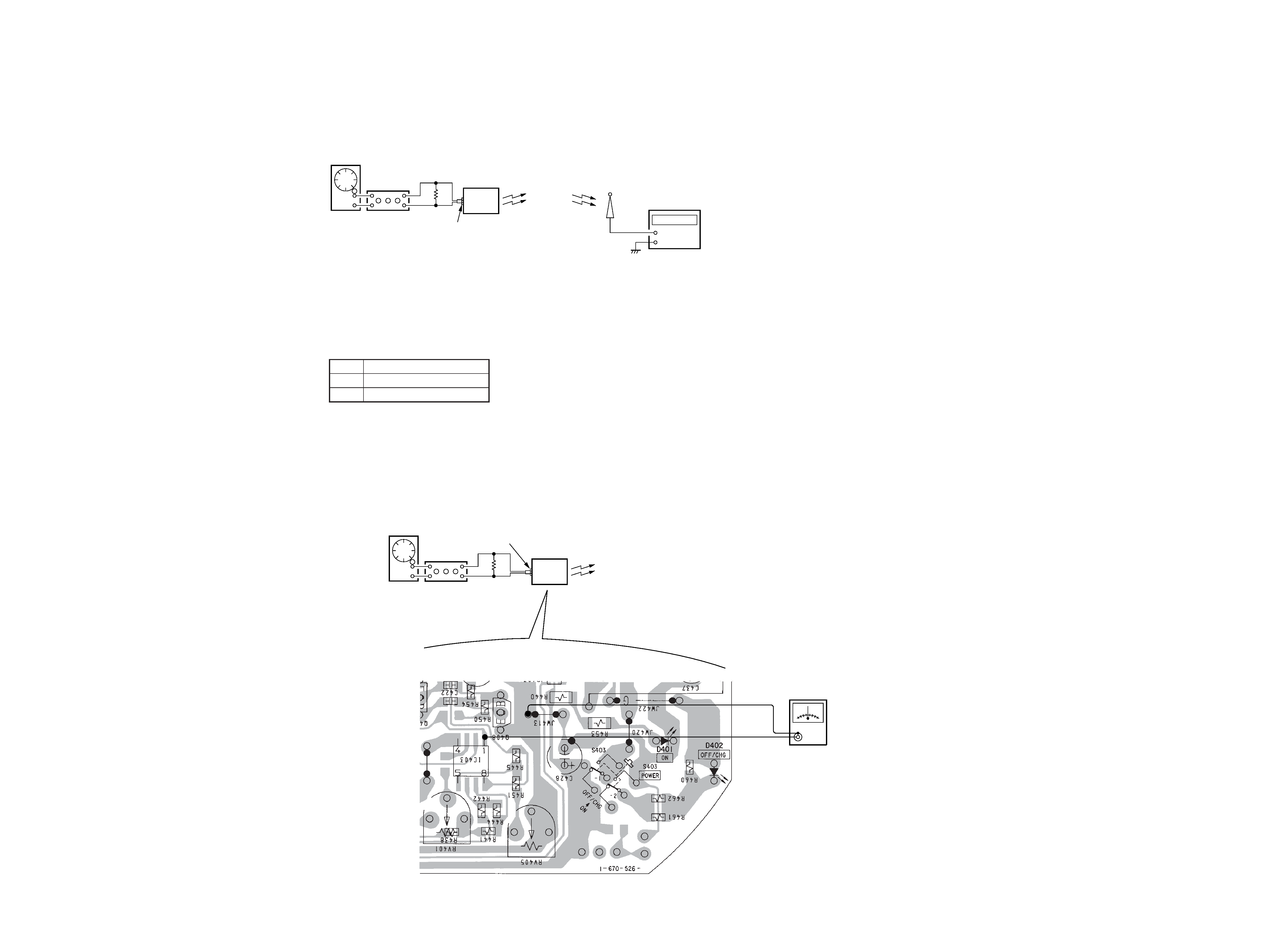
Preparation:
Procedure:
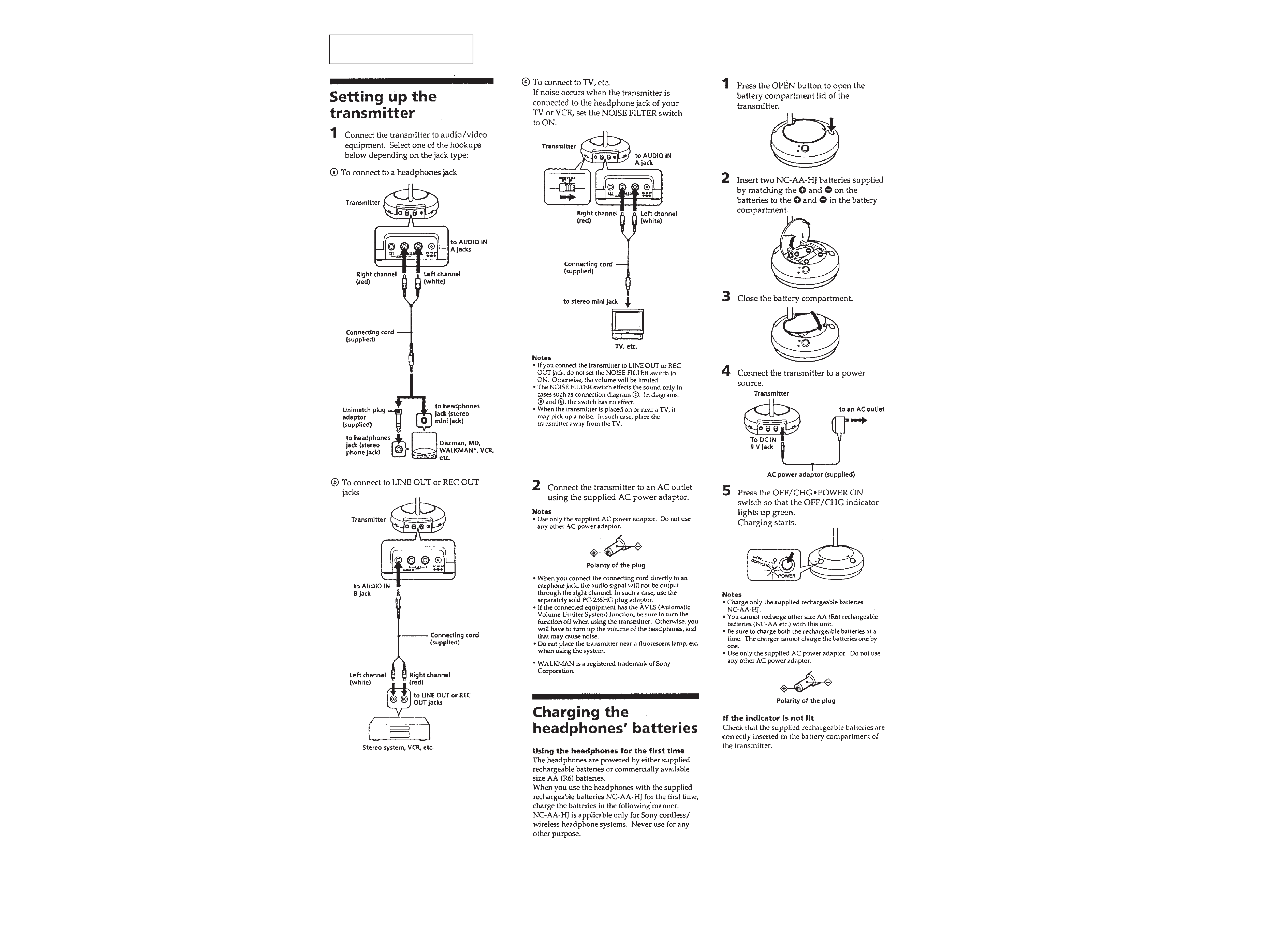
1. Turn OFF the noise filter switch (S401) on the TX-BASE board.
2. Enter 1 kHz 40 mVrms signal only to the Lch (J403) on the TX-BASE board.
3. Connect a rod antenna to the input of frequency counter, and adjust its length to about 8 cm.
4. Install the set in the vicinity of frequency counter, and check that the frequency on each channel is as specified value.
Specified value:
CH1
913.0 MHz
± 100 kHz
CH2
914.0 MHz
± 100 kHz
CH3
915.0 MHz
± 100 kHz
5. If out of the specified value, adjust the frequency by rotating RV402 and RV403 on the TX-BASE board.
6. After adjustment, recheck the frequency on CH1, CH2, and CH3.
Adjustment Location: TX-BASE board (See page 6.)
2-2.
Degree of Modulation of Subcarrier (L R) Check and Adjustment
Preparation:
AF OSC
ATT
AUDIO IN (J403: Lch)
1 kHz 40 mVrms
600
Trans-
mitter
+
+
TMR-RF950R
+
frequency counter
+
AF OSC
ATT
AUDIO IN (J403: Lch)
1 kHz 316 mVrms
600
Trans-
mitter
+
+
TMR-RF950R
+
AC voltmeter
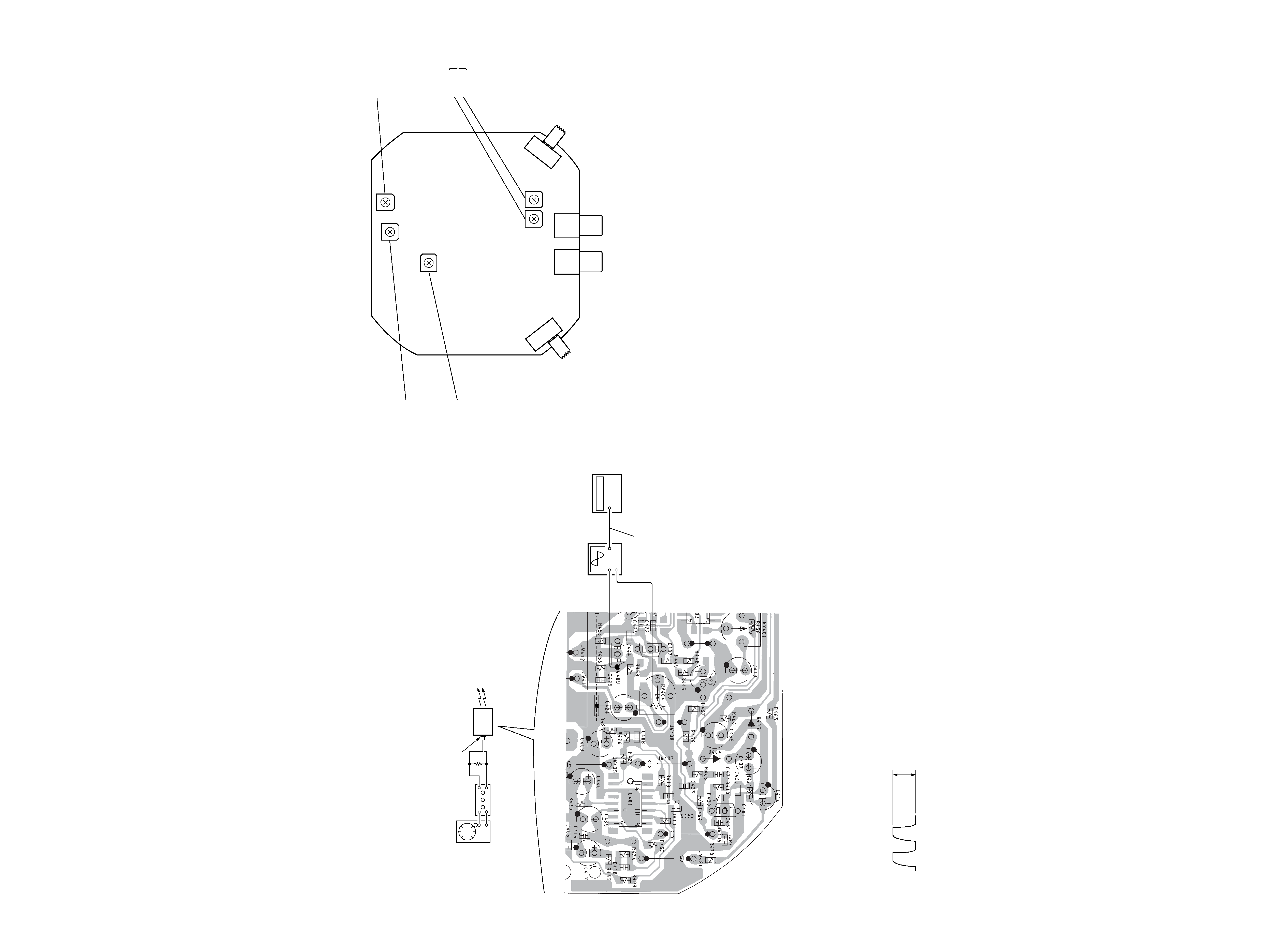
[TX-BASE board] Conductor Side
Procedure:
1. Turn OFF the noise filter switch (S401) on the TX-BASE board.
2. Set the channel select switch (S402) on the TX-BASE board to CH2.
3. Enter 1 kHz 316 mVrms signal only to the Lch (J403) on the TX-BASE board.
4. Connect a frequency counter and an oscilloscope between emitter of Q409 and ground on the TX-BASE board.
5. Turn off the input to the Lch on the TX-BASE board. (If the input is not turned off, the subcarrier is modulated and it cannot be
measured.)
6. Check that the frequency counter indicates 48 kHz to 52 kHz.
7. If out of the specified value, adjust the frequency by rotating RV405 on the TX-BASE board so as to attain 50 kHz. Also, check that the
waveform on oscilloscope is as shown below.
Note:
As the transmitter turns off automatically about one minute after the input to Lch of transmitter was turned off, checking and adjustment must be performed
within one minute. If it turned off automatically, again turn on the input to Lch to turn on the transmitter automatically, then turn off the input to Lch and
perform checking and adjustment.
5
6
Procedure:
1. Turn OFF the noise filter switch (S401) on the TX-BASE board.
2. Set the channel select switch (S402) on the TX-BASE board to CH2.
3. Enter 1 kHz 316 mVrms signal only to the Lch (J403) on the TX-BASE board.
4. Using on AC voltmeter, measure the voltage of IC403 pin 1 on the TX-BASE board to check that it is 220 mVrms to 250 mVrms.
5. If out of the specified value, adjust the voltage by rotating RV401 on the TX-BASE board so as to attain 235 mVrms.
Adjustment Location: TX-BASE board (See page 6.)
2-3.
Subcarrier Level and Frequency Check and Adjustment
Preparation:
AF OSC
ATT
AUDIO IN (J403: Lch)
1 kHz 316 mVrms
600
Trans-
mitter
+
+
TMR-RF950R
+
Adjustment Location:
+
oscilloscope
IN
frequency counter
OUT
coaxial cable
[TX-BASE board] C0nductor Side
RV405
Subcarrier Level
and Frequency
Adjustment
RV402
RV403
Transmission
Frequency
Adjustment
RV404
Degree of
Modulation of
Main Carrier (L + R)
Adjustment
(Please refer to
MDR-RF950
Service manual for
this adjustment)
RV401
Degree of
Modulation of
Subcarrier (L R)
Adjustment
NOISE
FIL
TER
OFF
~
ON
J402
(Rch)
J403
(Lch)
S402
CHANNEL
CH1
~
CH2
~
CH3
S401
[TX-BASE board] Component Side
3.6 Vp-p
± 0.2 V