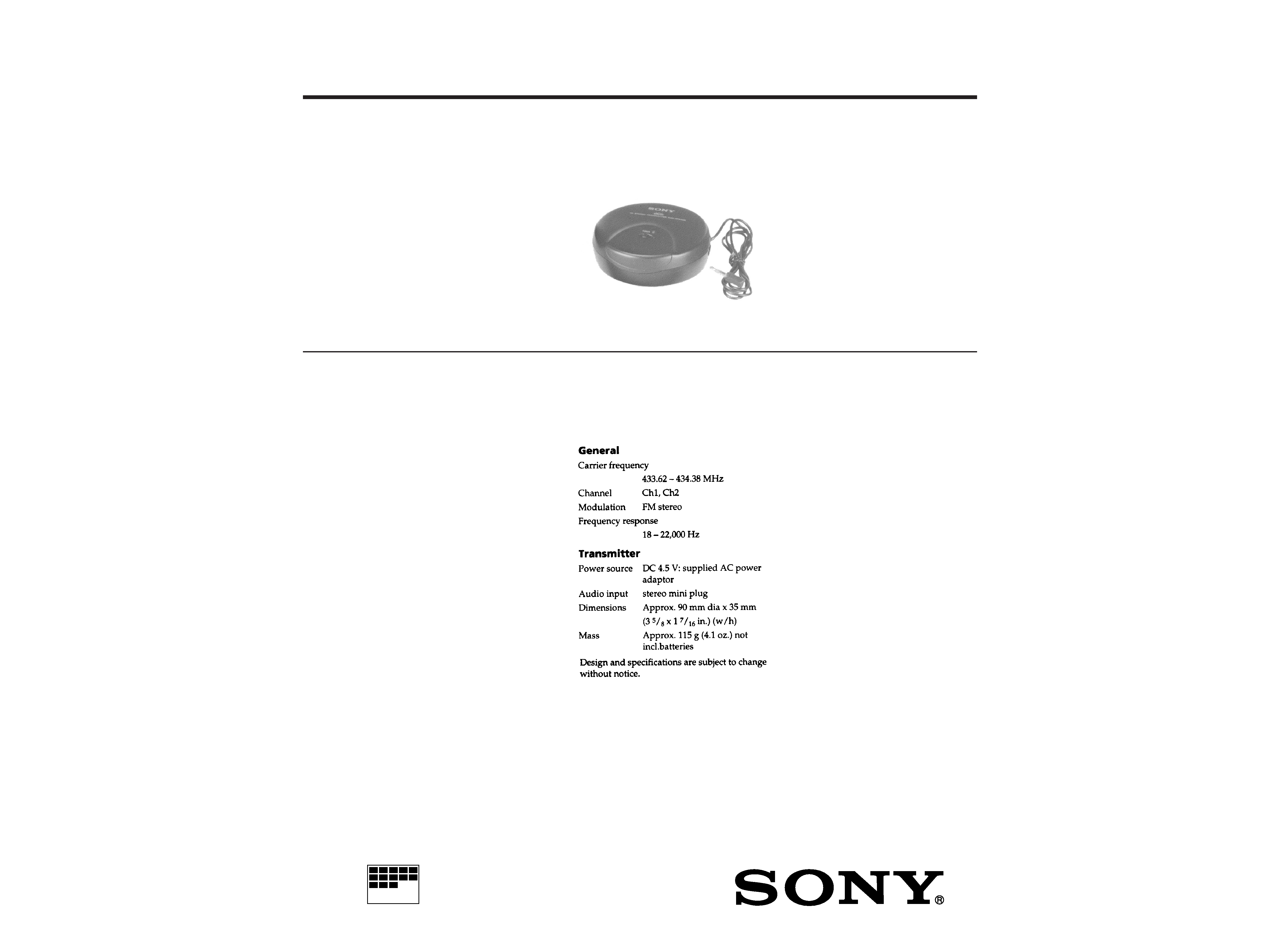
TRANSMITTER
MICROFILM
AEP Model
SPECIFICATIONS
SERVICE MANUAL
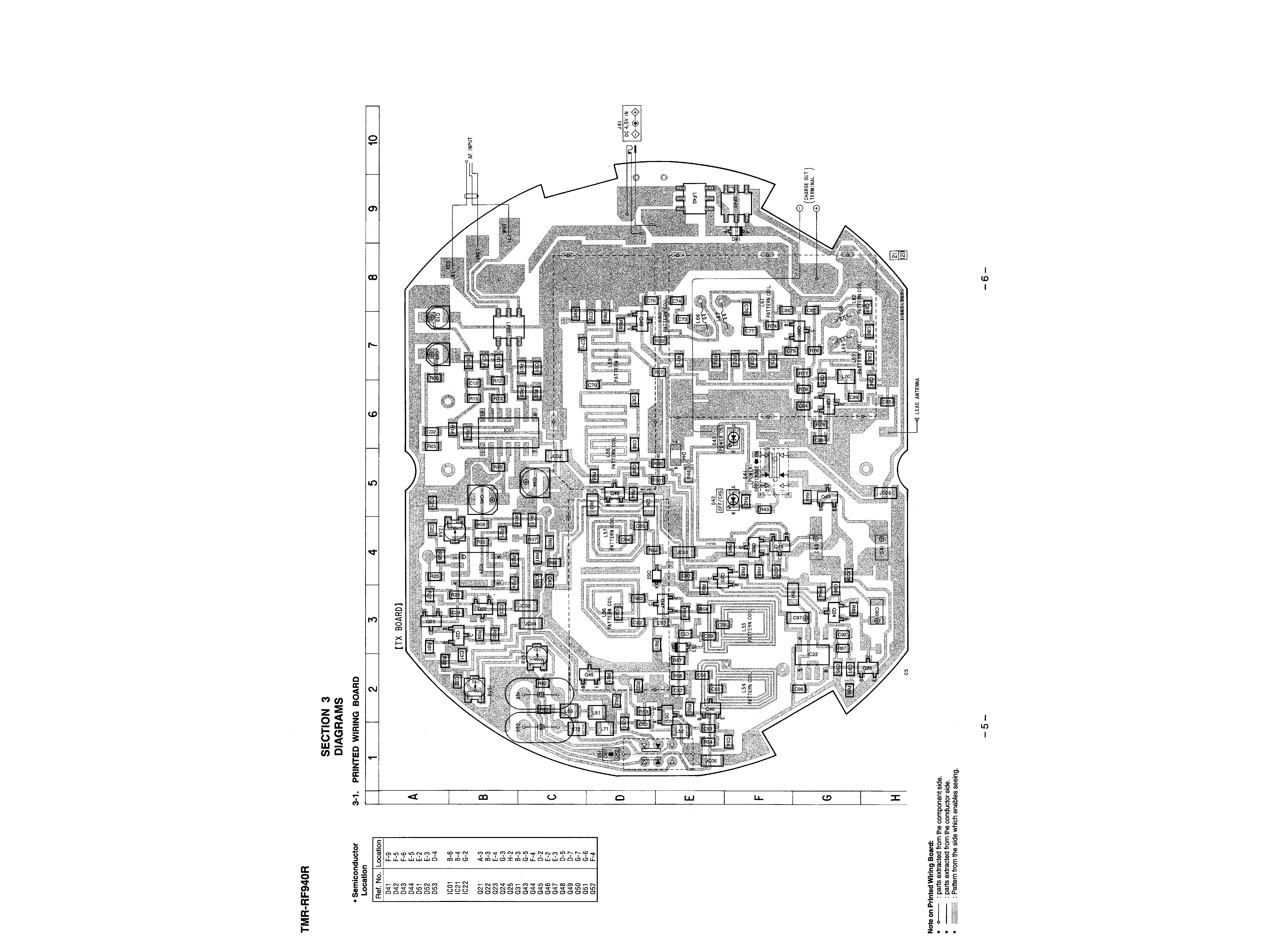
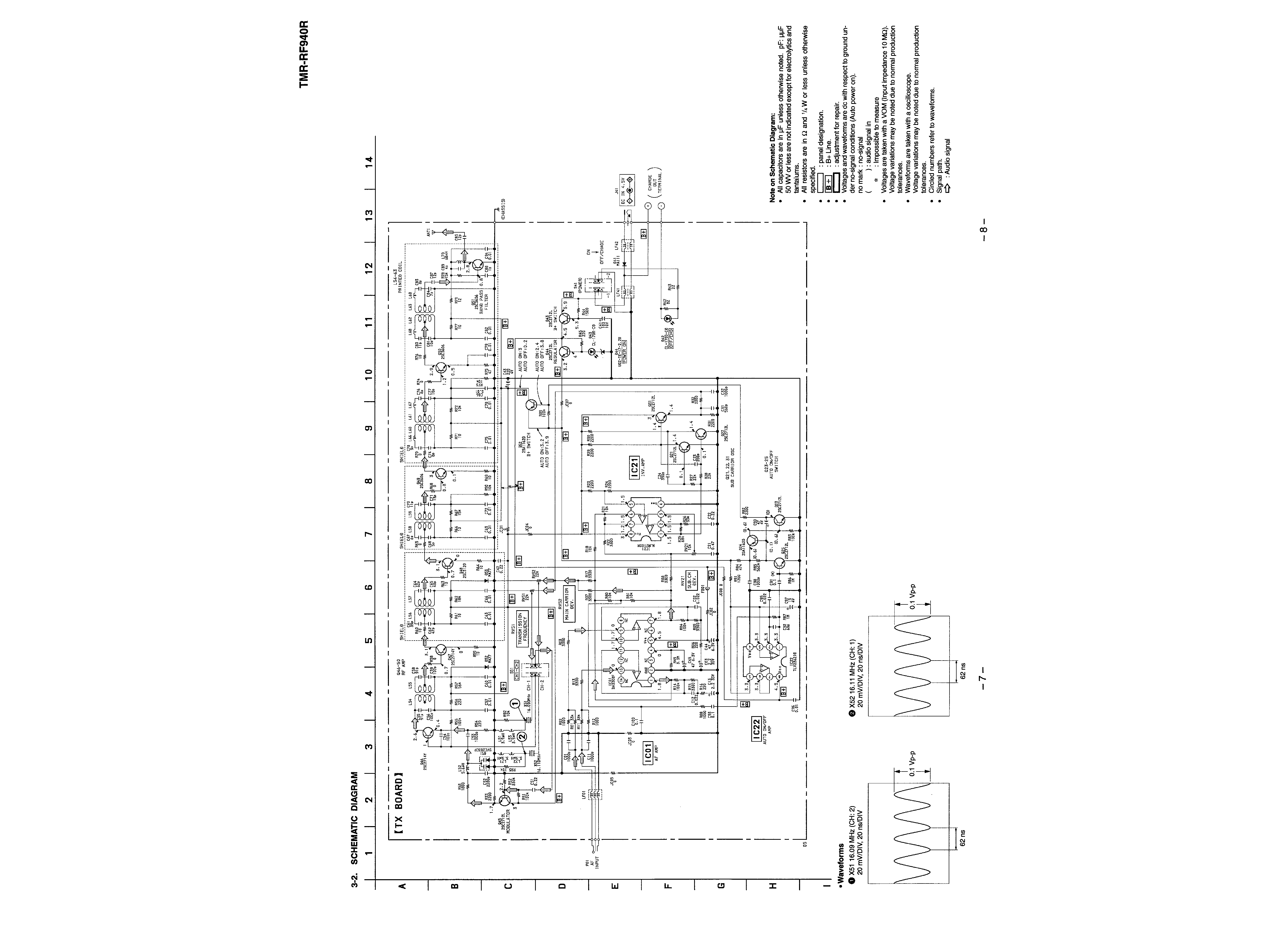
TMR-RF940R
TMR-RF940R is transmitter
unit in MDR-RF940RK.
2
Notes on chip component replacement
· Never reuse a disconnected chip component.
· Notice that the minus side of a tantalum capacitor may be dam-
aged by heat.
Flexible Circuit Board Repairing
· Keep the temperature of the soldering iron around 270 °C during
repairing.
· Do not touch the soldering iron on the same conductor of the
circuit board (within 3 times).
· Be careful not to apply force on the conductor when soldering or
unsoldering
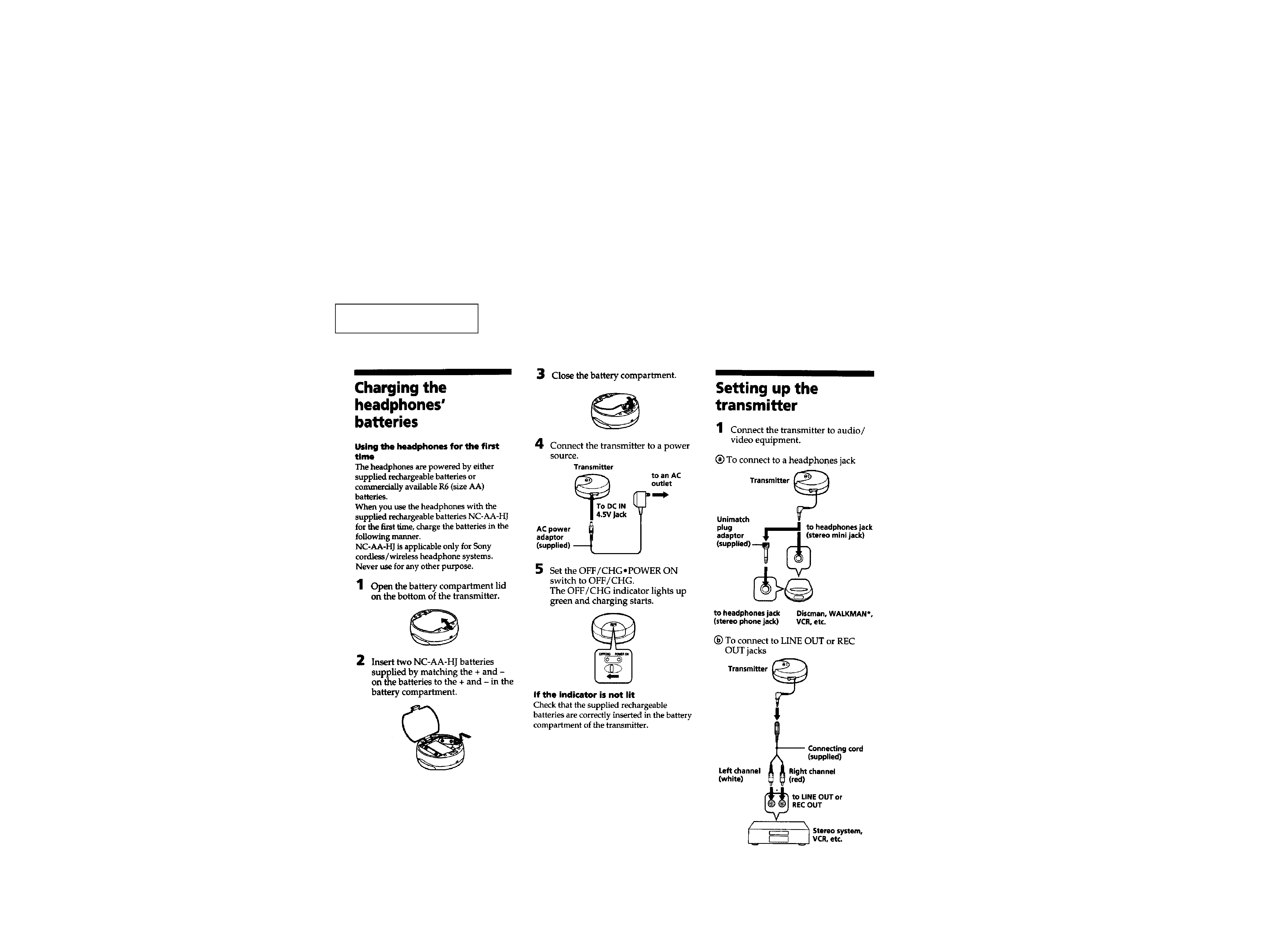
This section is extracted from
instruction manual.
SECTION 1
GENERAL
3
4
SECTION 2
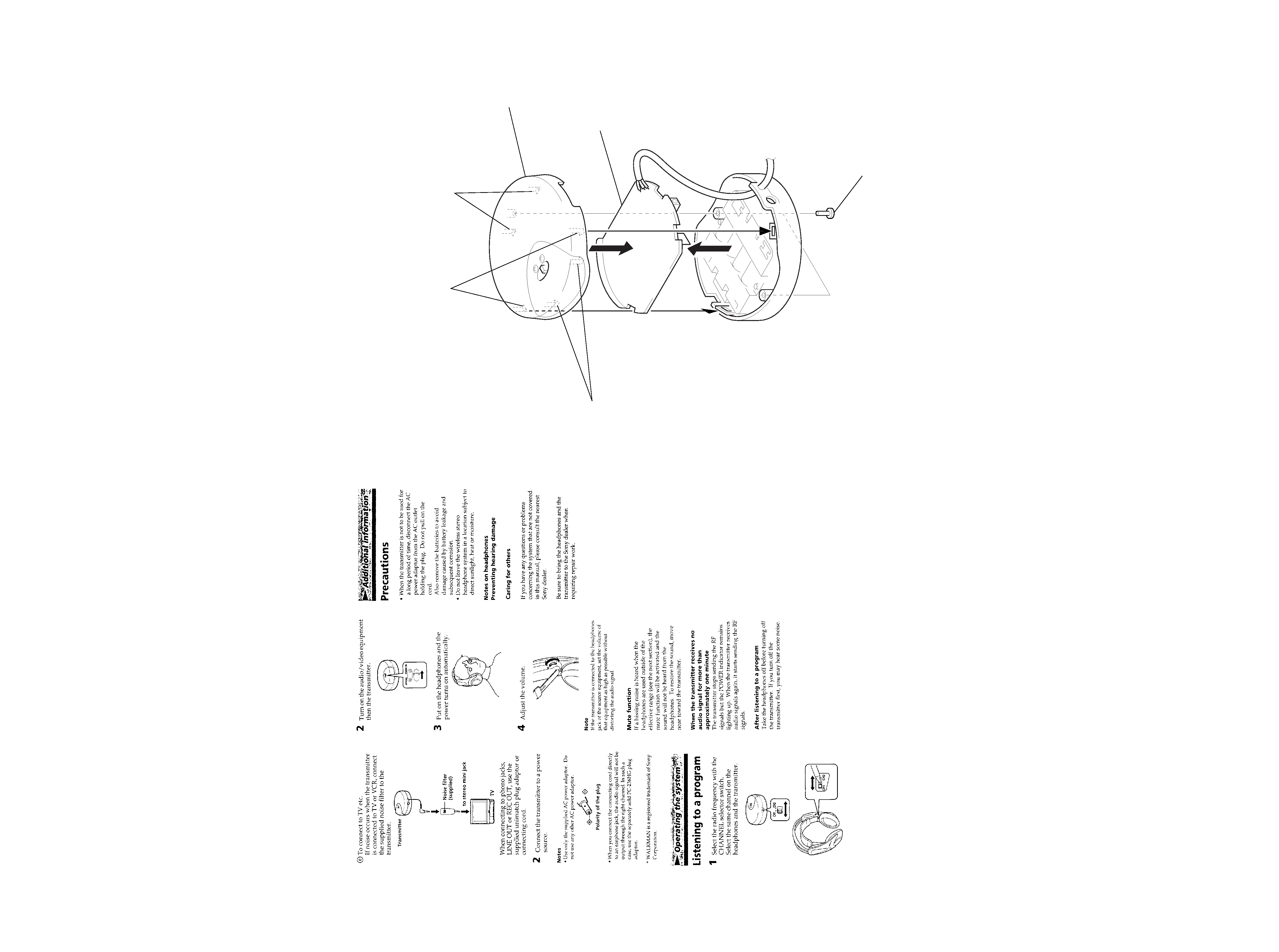
DISASSEMBLY
Note: Follow the disassembly procedure in the numerical order given.
CABINET (UPPER) ASS'Y
4 two claws
2 two claws
4 two claws
3 cabinet (upper) ass'y
5 TX board
1 two screws
(P2.6
× 10)