TMR-RF415R
AEP Model
SERVICE MANUAL
TRANSMITTER
Sony Corporation
Audio Entertainment Group
General Engineering Dept.
9-873-073-11
2001B1600-1
© 2001.2
Ver 1.0 2001. 02
SPECIFICATIONS
Headphones
MDR-RF415R
Transmitter
TMR-RF415R
TMR-RF415R is the component model block one in the MDR-RF415RK.
COMPONENT MODEL NAME FOR MDR-RF415RK
Power source
DC 9 V: supplied AC power adaptor
Audio input
phono jacks/stereo mini jack
Dimensions
Approx. 150 mm dia
× 108 mm
(6
× 4 1/3 in.) (w/h)
Mass
Approx. 190 g (6.7 oz.)
Design and specifications are subject to change without notice.
2
TMR-RF415R
SECTION 1
GENERAL
This section is extracted
from instruction manual.
DC IN 9V
OFF ON
FILTER
NOISE
12 3
CHANNEL
R
BA
L
AUDIO IN
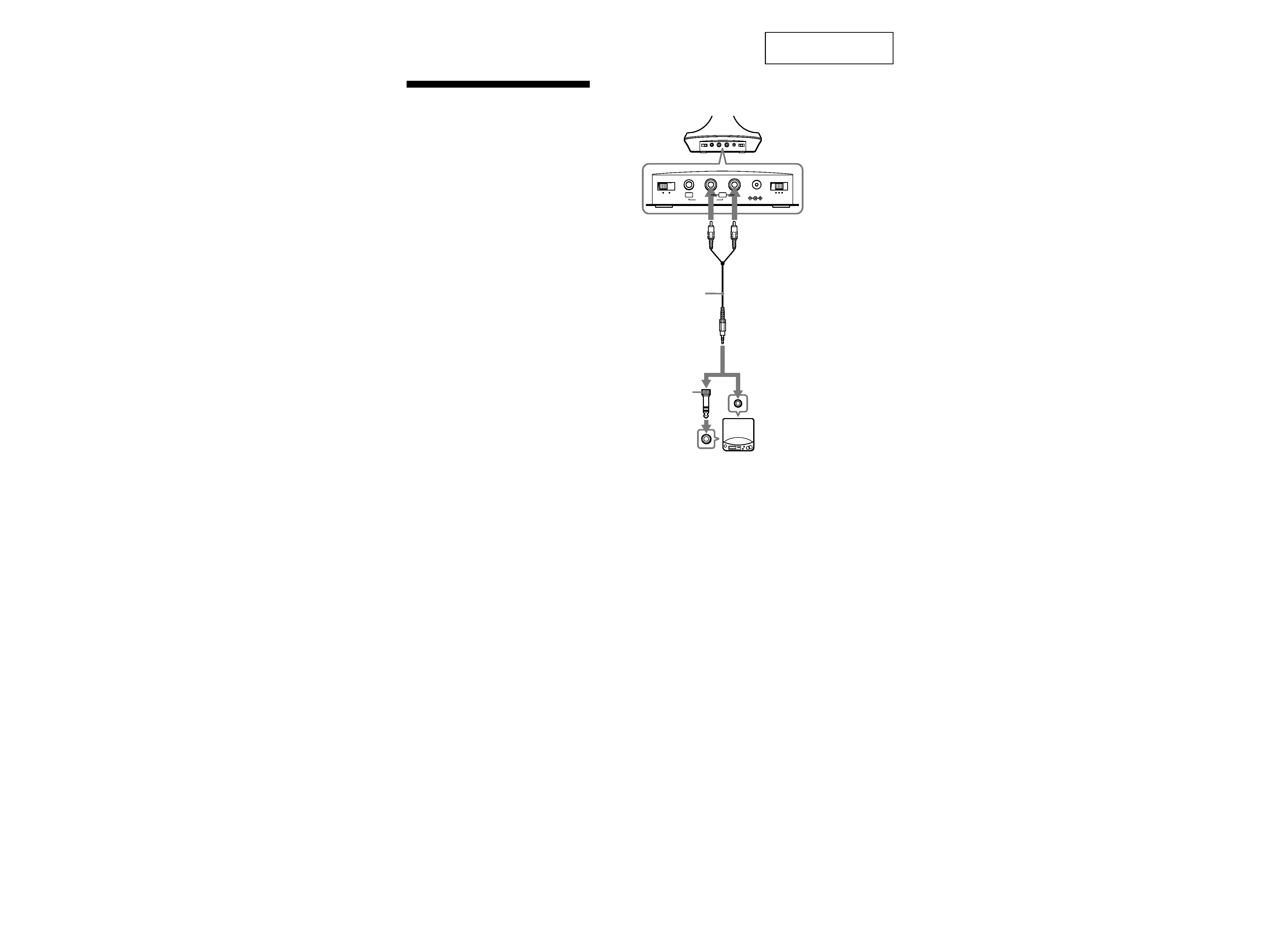
Setting up the
transmitter
1 Connect the transmitter to audio/video
equipment. Select one of the hookups
below depending on the jack type:
A
To connect to a headphones jack
Transmitter
Left channel
(white)
Right channel
(red)
Unimatch plug
adaptor
(supplied)
CD Walkman,
MD Walkman,
WALKMAN*,
VCR, etc.
to headphones
jack (stereo
mini jack)
Connecting cord
(supplied)
to AUDIO IN
A jacks
to headphones
jack (stereo
phone jack)
Notes on chip component replacement
· Never reuse a disconnected chip component.
· Notice that the minus side of a tantalum capacitor may be
damaged by heat.
3
TMR-RF415R
SECTION 2
DISASSEMBLY
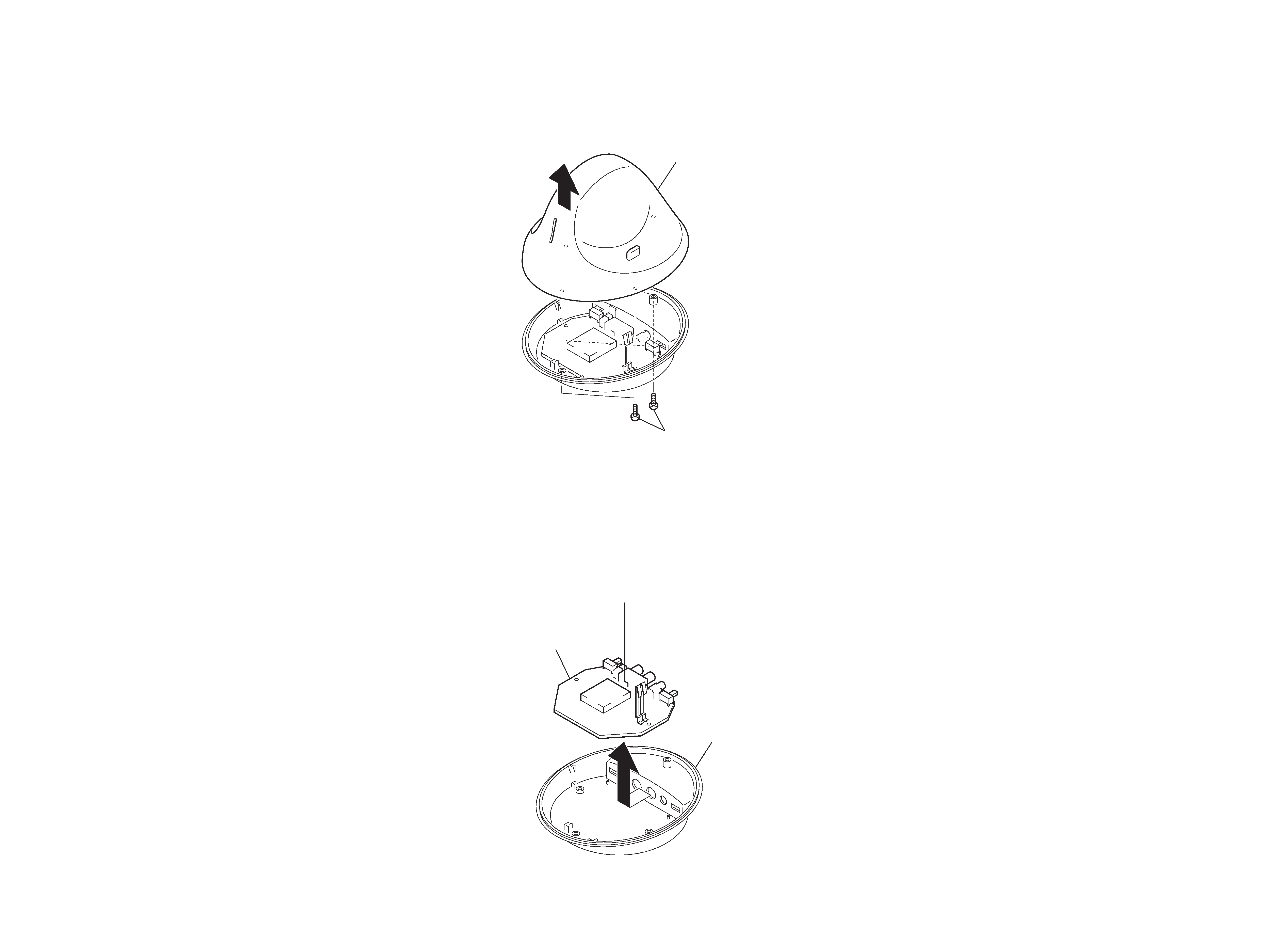
2-1. CABINET (UPPER)
2-2. TX-BASE BOARD
1
Four screws (P 2
× 8)
Cabinet (upper)
2
2
TX-BASE board
Cabinet assy, lower
1
Note :
Follow the disassembly procedure in the numerical order given.
4
TMR-RF415R
Setting :
SECTION 3
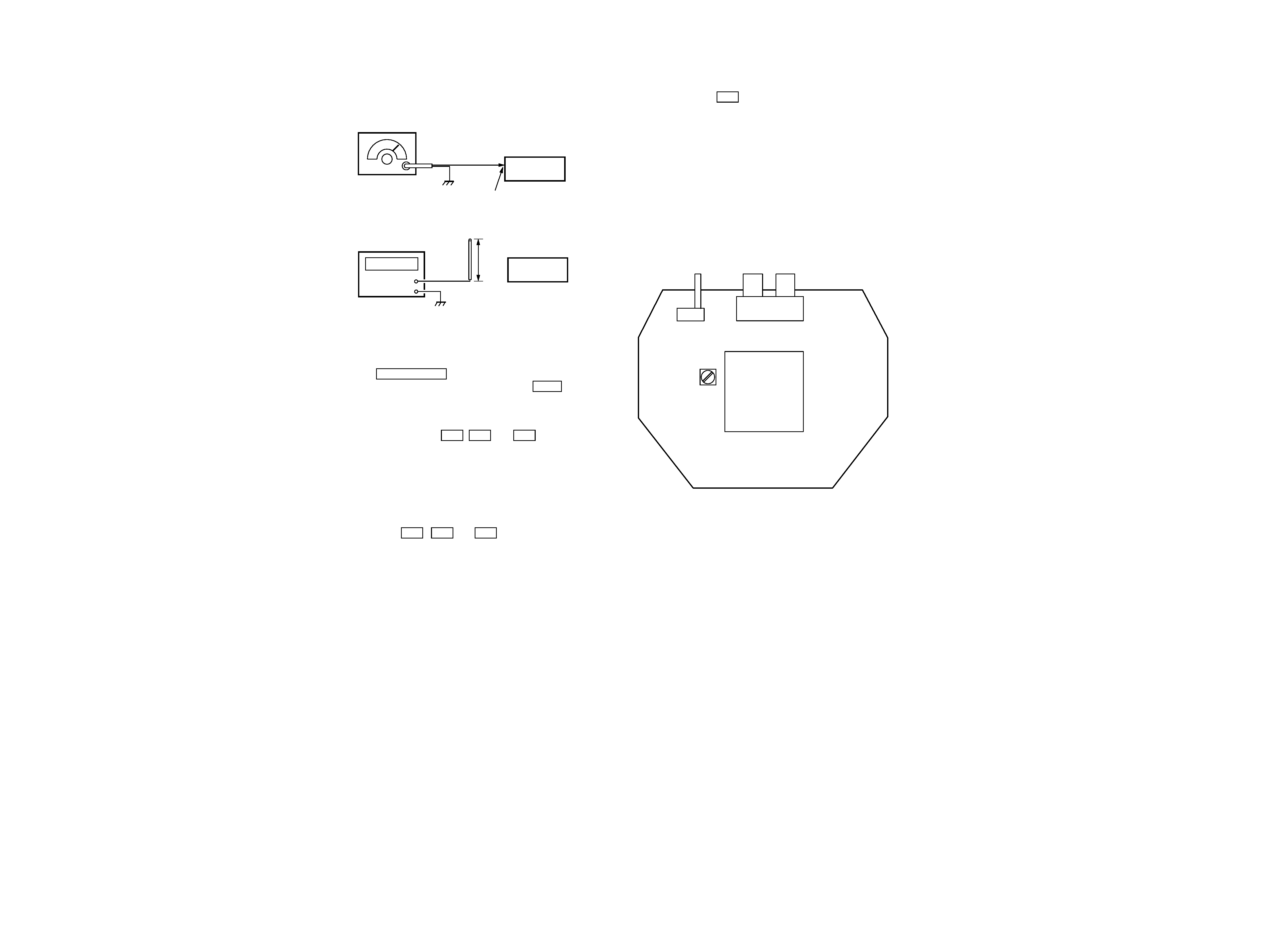
ELECTRICAL ADJUSTMENTS
Send Frequency Check
1. Set the NOISE FILTER switch to OFF.
2. Input a signal of 1 kHz 40 mVrms to only the L-CH (J402).
3. Connect a telescopic antenna to the frequency counter input
and extend the antenna to a length of approximately 8 cm.
4. Place TX-BASE board close to the frequency counter, then mea-
sure the frequencies of CH1 , CH2 and CH3 and make sure
the values are as follows:
CH1 : 433.5 MHz
± 40 kHz
CH2 : 434.0 MHz
± 40 kHz
CH3 : 434.5 MHz
± 40 kHz
When the frequency is not satisfied the specified value, exchange
vco unit. When completed with replacement, recheck the
frequecies of CH1 , CH2 and CH3 .
[TK-BASE BOARD] (Component side)
AF signal
generator
Telescopic
antenna
8 cm
L-CH (J402)
TMR-RF415R
set
TMR-RF415R
set
Frequency counter
Pilot signal Modulation Check and Adjustment
1. Set the channel to CH2 .
2. No signal input (The operating time in this case is limited to 4
or 5 minutes.)
3. Measure the movable terminal of RV403 using an digital volt-
meter (AC range) and make sure the value is 1.6mVrms
± 0.1mV.
If the measured value is other than the specified value, adjust to
1.6mVrms
± 0.1mV by turning the RV403 on the TX-BASE
board.
Connection points and Adjustment Location :
S402
J402
(L-CH) (R-CH)
CH3
CH2 CH1
VCO UNIT
RV403
5
5
TMR-RF415R
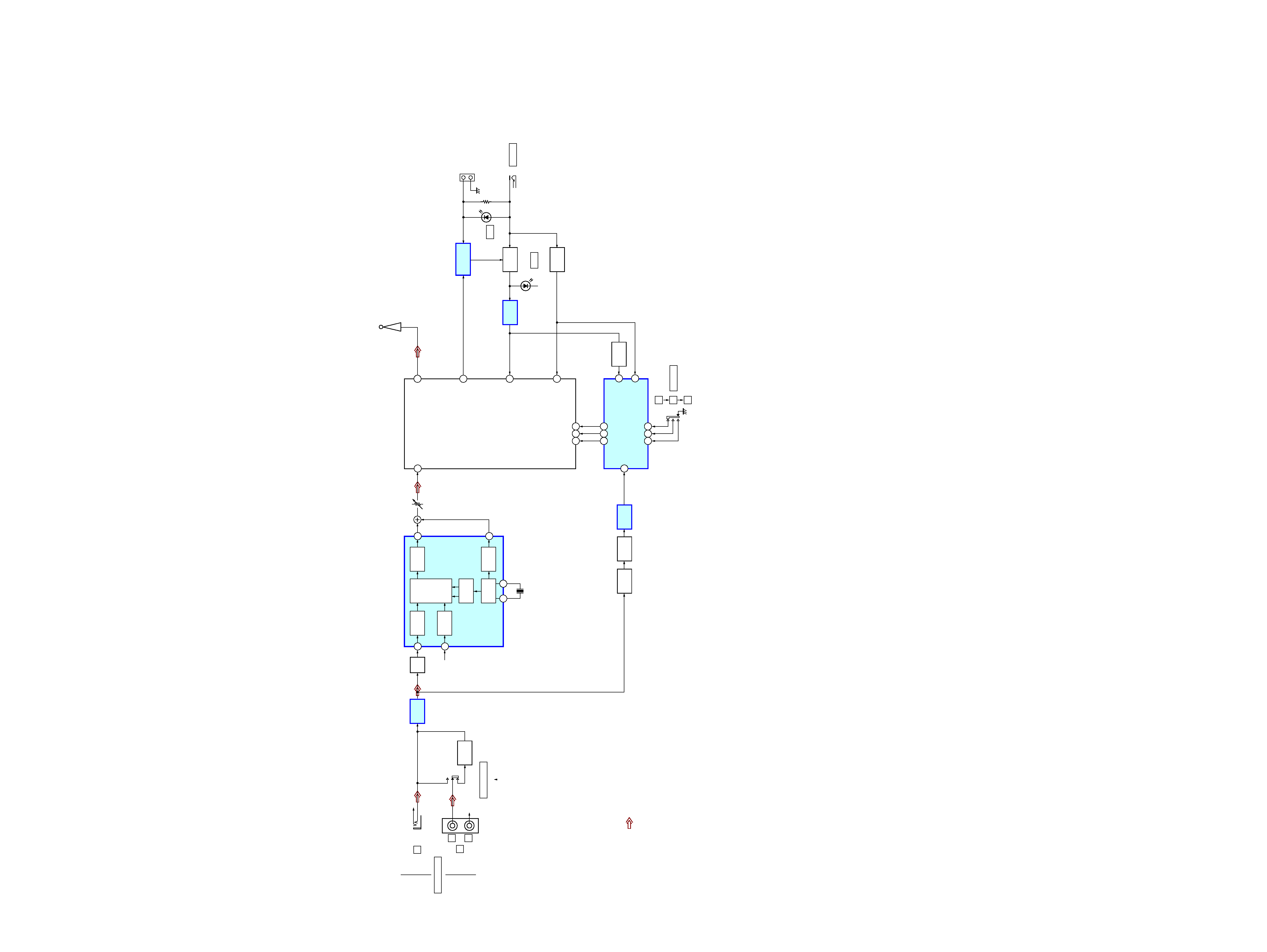
4-1. BLOCK DIAGRAM
SECTION 4
DIAGRAMS
· Signal path.
· R-ch is omitted.
: AUDIO
J401
S401
NOISE FILTER
NOISE
FILTER
INPUT
AMP
CH1
AMP
BUFFER
BUFFER
Q401
RECT
D404,405
2V
D408
INPUT
DET
DIVIDER
BUFFER
OSC
AMP
TIME
DEVISION
MPX
AUDIO IN
B
J402
A
OFF
|
ON
S402
CHANNEL
L
R
R-CH
R-CH
R-CH
1
9
8
13
10
12
11
6
7
9
15
7
6
CH2
AMP
14
X401
38kHz
RV403
MOD IN
CE DI CL
CE DI CL
VS
16
5V
VCO CONTROLLER
IC404
IC401
LPF
IC403
STEREO MPX
IC405(1/2)
IC405(2/2)
+5V
REG
SWITCH
Q404
+4V
Q402
POWER OFF
DET
IC402
ANT
5V
B+
T-OUT
ANTENNA
D401
D402
J404
DC IN 9V
(BATTERY CHARGER)
power
chg
1
2
3
VCO UNIT