TL-HA80
SERVICE MANUAL
HANDS FREE ADAPTOR
SPECIFICATIONS
US Model
9-873-108-11
2001E0200-1
© 2001.5
Photo : TL-HA80
Photo : TL-DR0140
Sony Corporation
Personal Audio Company
Shinagawa Tec Service Manual Production Group
Ver 1.0 2001.05
Headset (TL-DR0140)
Dimension (Cord)
Approx. 7 ft. (2m)
Dimension (Plug)
3.5 mm dia.
Mass
Approx. 0.88 oz (25 g) (without cord)
<Receiver>
Type
Open air dynamic
Driver units
30 mm dia. (CCAW Voice coil)
Sensitivity
104 dB/mW
Impedance
24
Maximum input power
1000 mW (IEC)
<Microphone>
Type
Close-talking pipe microphone
Unit
Back electret condenser
Output impedance
Under 2.2 k
Closed circuit voltage level
-47 dB (0 dB = 1 V/Pa)
Design and specifications are subject to change without notice.
Power source
DC 9V from AC power adaptor
Dimensions
Approx. 3 5/8 x 3 7/8 x 6 5/8 inches (w/h/d)
(92 x 96 x 165.5 mm)
Mass
Approx. 10.58 oz
(300 g)
Supplied accessories
AC power adaptor (AC-T127)
Telephone cord: approx. 1 ft. (30cm)
Stereo audio cable (stereo mini-plug):
approx. 3.5 ft. (1m)
Headset TL-DR0140
Headset hanger
2
TL-HA80
Specifications ........................................................................... 1
1. GENERAL ...................................................................... 2
2. DISASSEMBLY
2-1. Cabinet (Upper) ASSY ............................................... 4
2-2. Main noard, Volume board, Jack Bords ...................... 4
3. DIAGRAMS
3-1. Block Diagram ............................................................ 5
3-2. Schematic Diagram ..................................................... 6
3-3. Printed Wiring Boards ................................................ 7
4. EXPLODED VIEWS .................................................... 8
5. ELECTRICAL PARTS LIST ..................................... 9
TABLE OF CONTENTS
SECTION 1
GENERAL
This section is extracted from
instruction manual.
Notes on chip component replacement
· Never reuse a disconnected chip component.
· Notice that the minus side of a tantalum capacitor may be dam-
aged by heat.
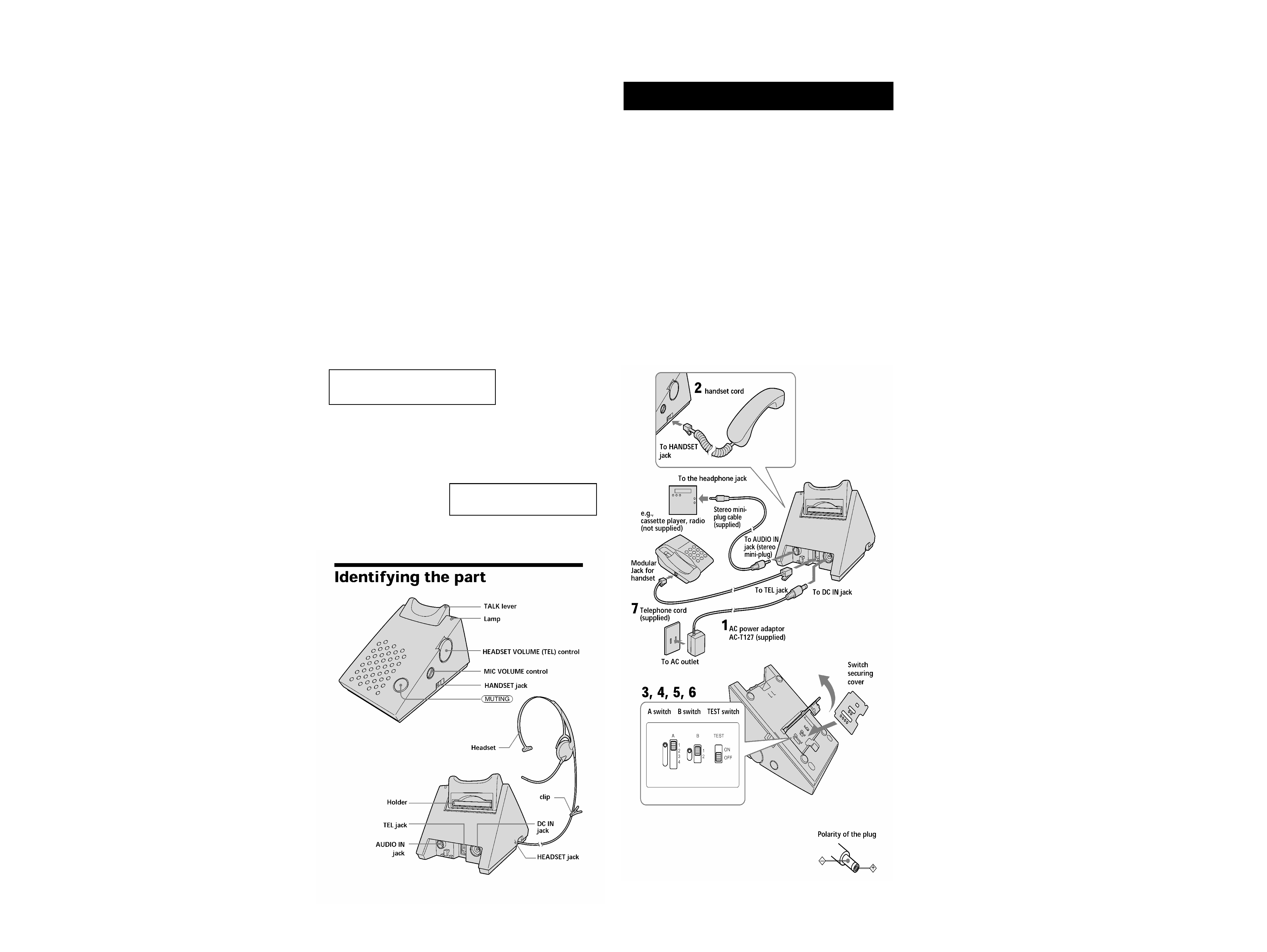
Setting up the unit
Connect the unit
1Connect the AC power adaptor to the DC IN jack and to an AC
outlet.
2Disconnect the handset cord from the handset jack on the phone
and connect the handset cord to the HANDSET jack of the unit.
3Open the cover on the bottom of this unit and remove the
switch securing cover.
4Turn ON the TEST switch and make sure that you can hear a
long confirmation beep from the speaker side on the handset.
If no long confirmation beep is heard from the speaker side on
the handset, see "If no long confirmation beep is heard" to select
the setting of the A and B switches.
5Turn OFF the TEST switch and put a switch securing cover.
6Close the cover on the bottom.
7Connect the telephone cord (supplied) to the phone and to the
TEL jack of the unit.
Notes
· Use only the supplied AC-T127 AC power adaptor. Do not
use any other AC power adaptor.
· Use only the supplied telephone cord. Do not use any other
telephone cord.
· Do not close the AC power adaptor. It may cause noises.
· During a power interruption, you cannot use this unit.
The components identified by mark 0 or
dotted line with mark 0 are critical for safety.
Replace only with part number specified.
3
TL-HA80
Tip
When an external equipment is connected to the AUDIO IN jack and the handset is not
placed on the TALK lever, the sound from the external equipment is connected to the
headset in either case that the handset is in the on-hook or off-hook status on the main
body of the phone.
Notes
· If your phone's handset does not stay on the TALK lever
and easily drops from it, pull up the holder and place the
handset as shown in the figure.
· Howling noise might occur depending on the connected
phone. In this case, lower the receiver HEADSET
VOLUME (TEL) control to a suitable position before use.
Additional tasks
Do this
Turn the HEADSET VOLUME (TEL) up to
increase the receiver volume or down to decrease it.
Put a coin, etc. in the slot of the MIC VOLUME
control, and turn right or left to adjust.
Adjust the microphone volume control to the
suitable position by asking another party on the
line to check.
Press
to disable the microphone. The
button lights up.
Press
again to cancel.
To
Adjust the receiver volume
Adjust the microphone
volume
Mute your voice
If no long confirmation beep is heard
1 Turn ON the TEST switch.
2 Set the A switch to the position (1 to 4) where a long
confirmation beep is heard.
If this doesn't work and no long confirmation beep is heard yet,
turn the B switch to 2 and then set the A switch to the position
where a long confirmation beep is heard.
Notes
· Depending on the handset, a long confirmation beep is heard from the microphone
side. Be sure to set the A and B switches to the position where a long confirmation
beep is heard from the speaker side.
· If you have connected this unit to another phone, follow the instructions described
in "Connect the unit".
Listening to music, etc. from an external equipment
If you want to listen to music, etc. from the external equipment, you can do
it using the headset during handset on-hook status.
Notes
· When you are listening to music, etc. with the external equipment connected to
AUDIO IN jack, HEADSET VOLUME (TEL) is not available. Volume control is
available with the connected equipment.
Also, turning off the sound from the connected equipment can be done either by
shutting down the power for the external equipment or by pulling out the stereo
audio cable from AUDIO IN jack on this unit.
· The sound of this unit is a monaural type.
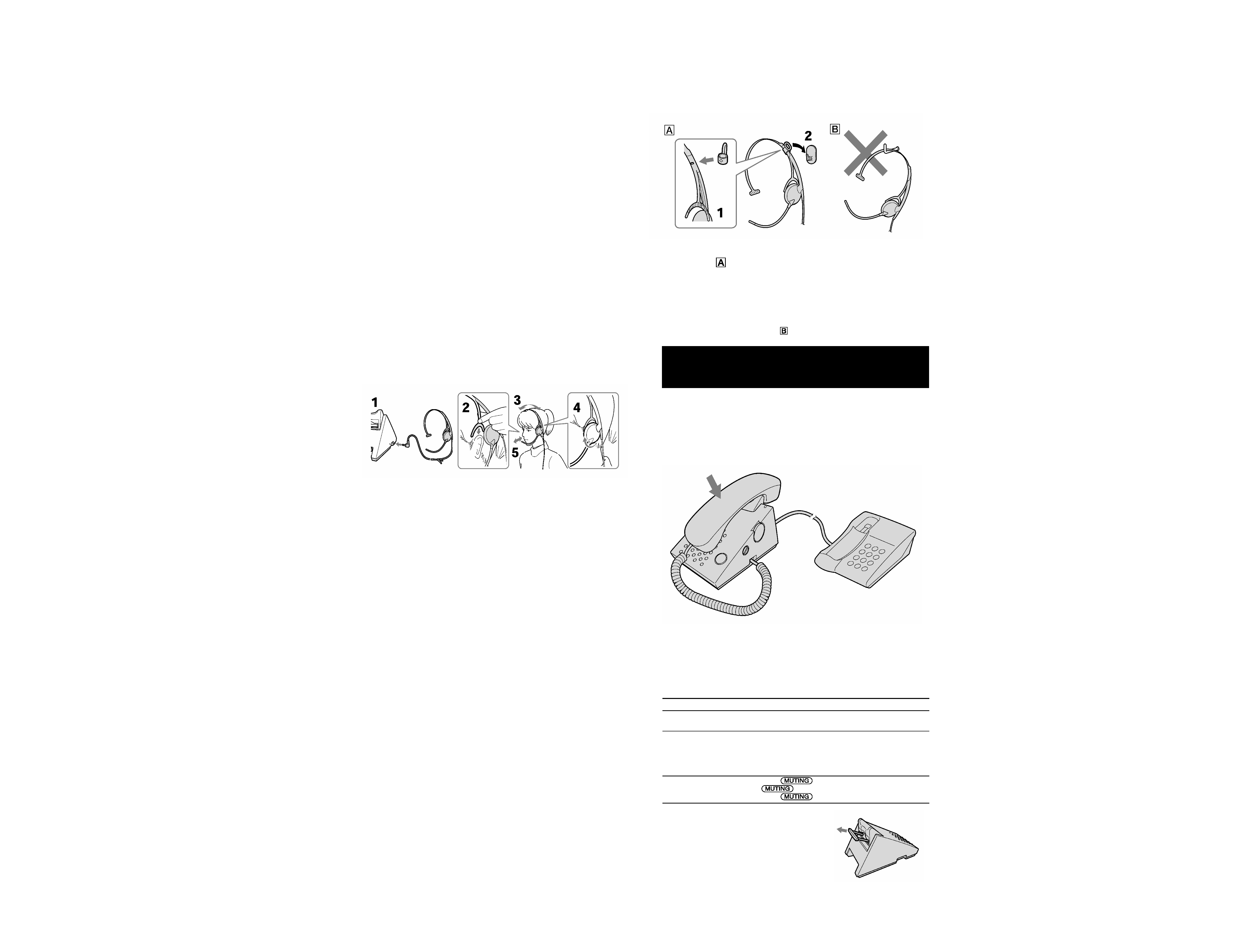
Connect the headset
1Connect the headset plug to the HEADSET jack.
2Place the earpiece support unit behind the top of your ear.
3Adjust the length of the headband so that the headset fits on
your ear.
4The earpiece can be rotated so it fits comfortably over either ear.
5Position the headset microphone so that it is placed near the
mouth.
Notes
· Listening with headset at high volume may affect your hearing.
· The earpad may deteriorate due to long-term storage or use. If you need to
replacing the earpad, it can be purchase separately (EP-Q1).
Tip
You can use the headset on either your right or left ear.
Using the headset hunger
The headset can be hung on the hook (supplied) by mounting the headset
hanger (supplied) on the headset.
Switching handset/headset
conversation
The handset/headset conversation can be switched by placing the handset
on the TALK lever.
When the handset is placed on the TALK lever: Headset conversation mode
When the handset is not placed on the TALK lever: Handset conversation
mode
1 Attach the headset hanger to the headset from the slit as
illustration
.
Be sure to insert the protrusion of the headset hanger to the
projection of the headset.
2 Hang the headset hanger on the hook.
Note
Do not hang the headset on as illustration
.
4
TL-HA80
SECTION 2
DISASSEMBLY
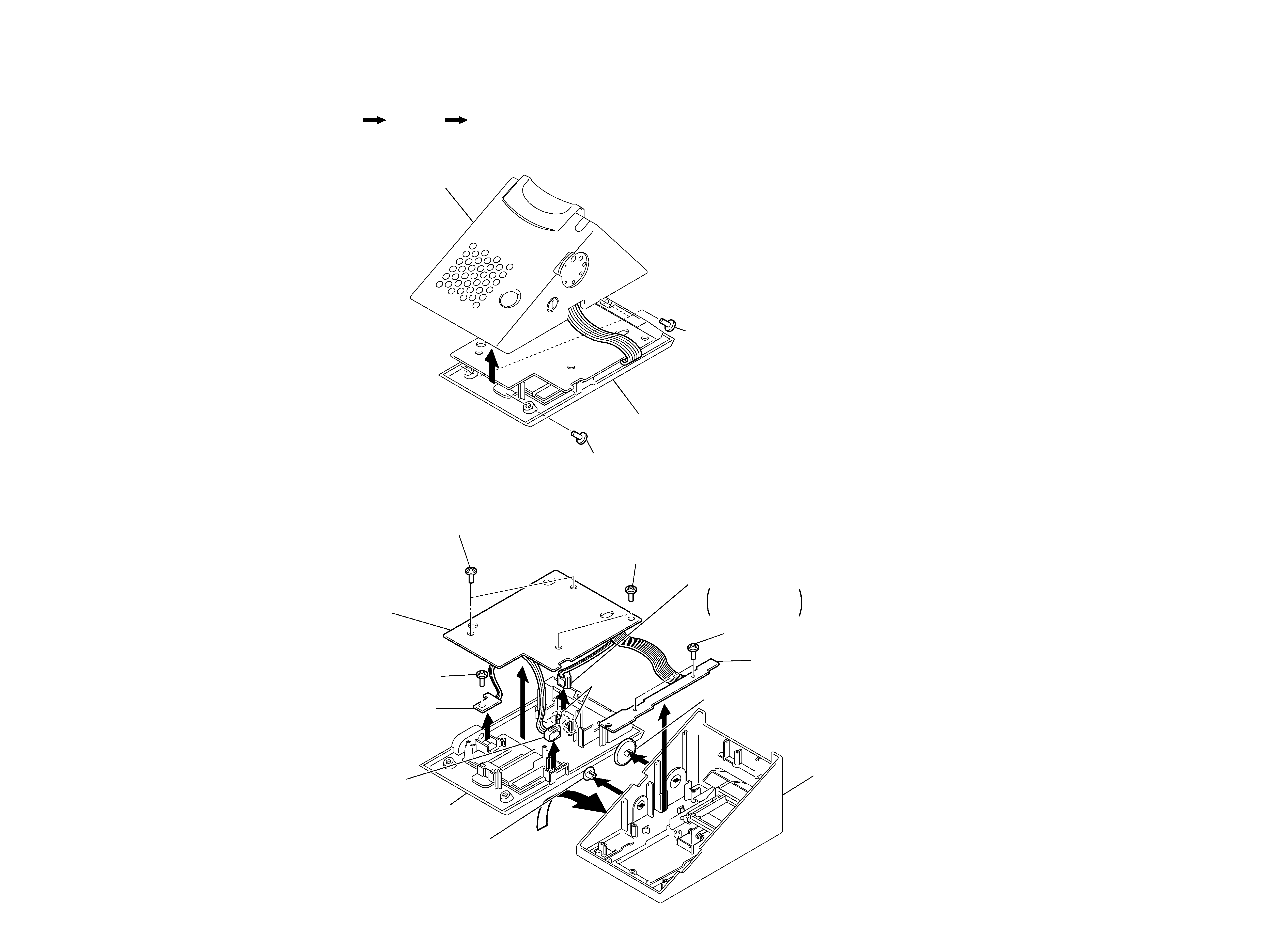
2-1. CASE (UPPER)
Note : Follow the disassembly procedure in the numerical order given.
2-2. MAIN BOARD, VOLUME BOARD, JACK BOARD
Case (upper)
Main board, Volume board, Jack board
Set
1 Screw (+BVTP3X10)
1 Screws (+BVTP3X10)
Case (upper)
Case (lower)
2
7 Screws (+BVTP2.6X8)
5 Screw (+BTP2.6X8)
6 Audio board
9 MJ102
Case (lower)
2 Knob (MIC)
1 Knob (VOL)
7 Screws (+BVTP2.6X8)
3 Screws (+BTP2.6X8)
qa
MJ101
Spred 0claws and
put qaMJ101 off from
the case (lower)
4 Volume board
0 Claws
Main board
Case (upper)
8
5
5
TL-HA80
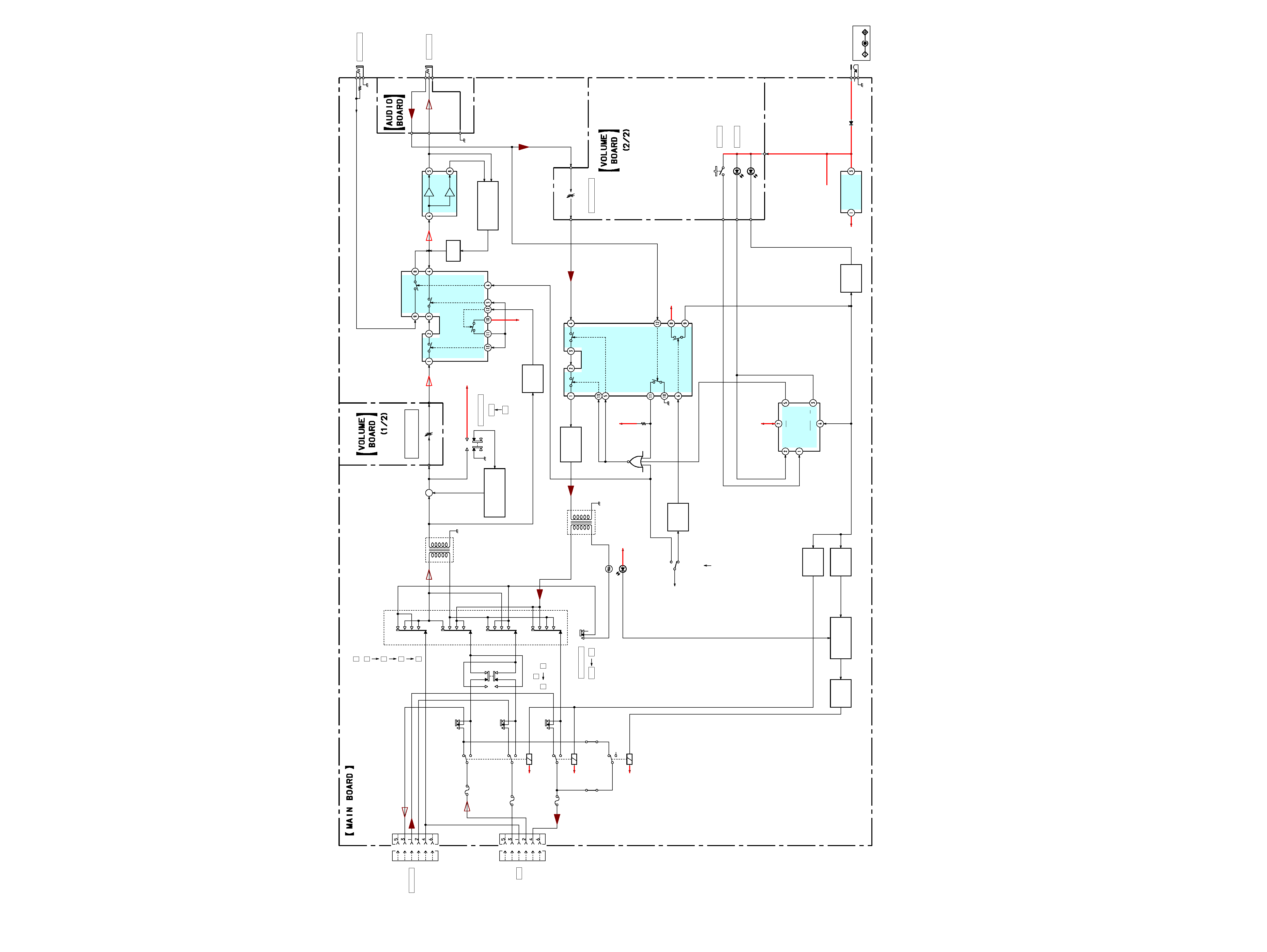
3-1. BLOCK DIAGRAMS
· Signal path.
H
: RX
O
: TX
SECTION 3
DIAGRAMS
J301
MJ102
MJ101
F101
F102
F103
T102
D201
D202
S201
J103
T101
CDS1
RY101
J105
RV202
RV201
S105
D104
JW103
JW203
S101
D106
RY102
RY103
250V
500mA
250V
500mA
250V
500mA
DC IN 9V
Q
CK
PR
CLR
Q
D
+
HEADSET
HANDSET
TEL
OFF
ON
S104
S102
B
2
1
S103
1
2
3
4
A
TEST MODE
ON
OFF
AMP
HEADPHONE
MUTING
(TEL)
HANDSET VOLUME
MUTING
(LINE)
MIC VOLUME
+5V REG
LED
DRIVER
MUTING
HOLD
ANALOG
SWITCH
RELAY
DRIVER
LED DRIVER
TALK
(HANDSET)
(HEADSET)
RELAY
DRIVER
Q106
Q109
Q108
/BUFFER
DELAY
D109
DELAY
IC101
MIC AMP
Q101,102
+5V
IC102
+5V
ANALOG
SWITCH
IC105
Q112
MUTE
Q110,111
LEVEL DETECT
IC103
AUDIO IN
+5V
IC104
+5V
+5V
DELAY
SIGNAL
TEST
GENERATOR
Q104,105
+5V
+5V
D107
RY101-2
RY101-1
RY102-1
RY103-1
Q107
VDD
VDD
OR
Q103
S103-A
S103-B
S103-C
S103-D
TEST MODE
S104-D
S104-C
S104-B
S104-A
+5V
D108
VDD
VDD