1
Model Name Using Similar
Mechanism
TC-WE505/WE605S/WE705S
TC-WE625 : TCM-190RB12CL
DECK A
TC-WE725/WE825S :
Tape Transport
TCM-190RB13C
Mechanism Type
TC-WE625 : TCM-190RB12CL
DECK B
TC-WE725/WE825S :
TCM-190RB11C
SERVICE MANUAL
US Model
TC-WE625/WE825S
Canadian Model
TC-WE625
AEP Model
UK Model
TC-WE725/WE825S
E Model
Australian Model
Chinese Model
TC-WE625
TC-WE625/WE725/
WE825S
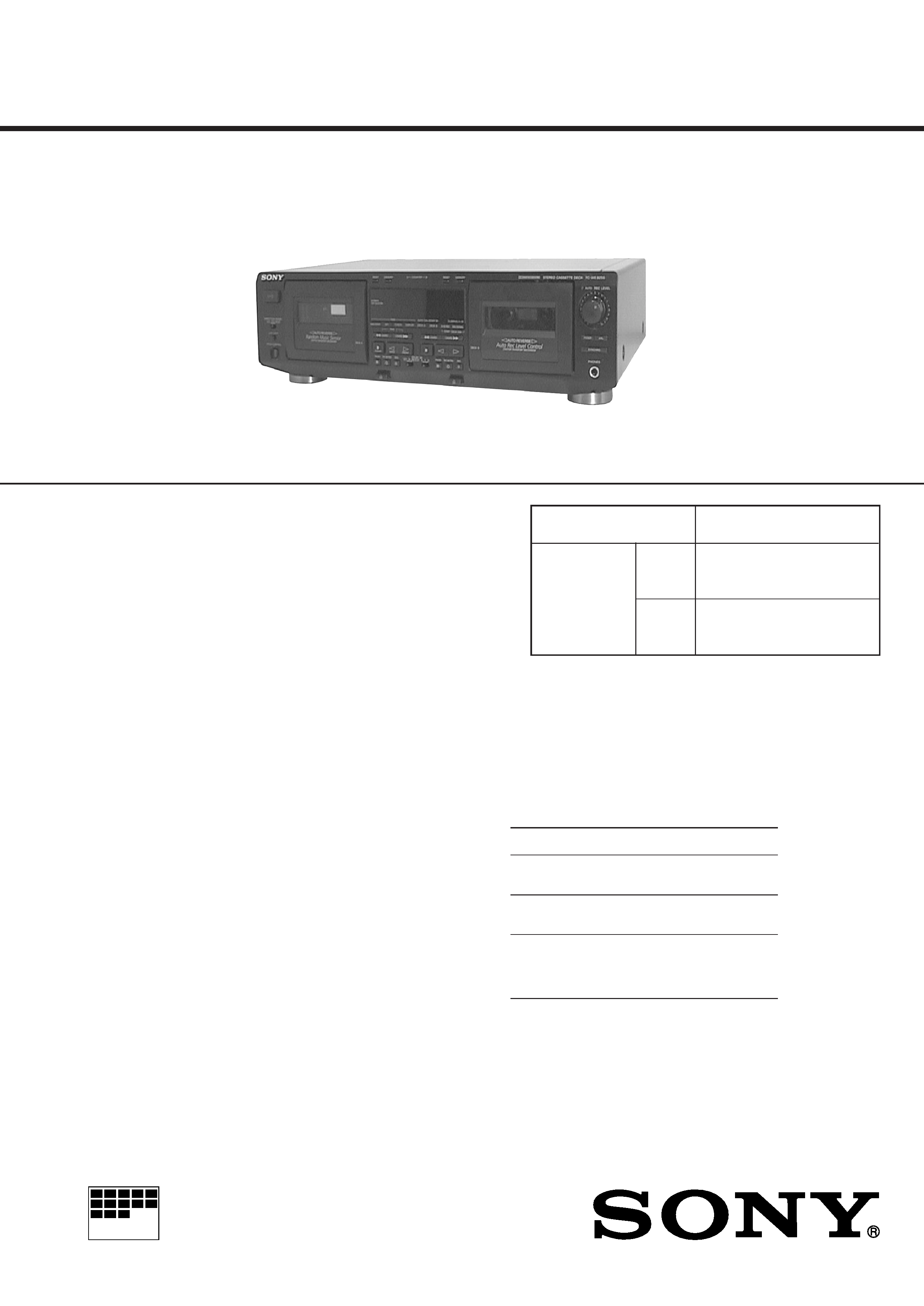
STEREO CASSETTE DECK
MICROFILM
System
Recording system
4-track 2-channel stereo
Fast-winding time (approx.)
90 sec. (with Sony C-60 cassette)
High-speed fast-winding time (approx.) (TC-WE825S and TC-WE725
only)
45 sec. (with Sony C-60 cassette)
Bias
AC bias
Signal-to-noise ratio (at peak level and weighted with Dolby NR off)
Type I tape, Sony Type I (NORMAL): 55 dB
Type II tape, Sony Type II (HIGH): 57 dB
Type IV tape, Sony Type IV (METAL): 58 dB
S/N ratio improvement (approximate values)
With Dolby B NR on: 5 dB at 1 kHz, 10 dB at 5 kHz
With Dolby C NR on: 15 dB at 500 Hz, 20 dB at 1 kHz
With Dolby S NR on (TC-WE825S only): 10 dB at 100 Hz,
24 dB at 1 kHz
SPECIFICATIONS
Continued on next page
Photo: TC-WE825S
Dolby noise reduction extension manufactured under license
from Dolby Laboratories Licensing Corporation.
HX Pro originated by Bang & Olufsen. "DOLBY", the double-D
symbol
a and "HX PRO" are trademarks of Dolby Laboratories
Licensing Corporation.
Harmonic distortion
0.4% (with Type I tape, Sony Type I (NORMAL):
160 nWb/m 315 Hz, 3rd H.D.)
1.8% (with Type IV tape, Sony Type IV (METAL):
250 nWb/m 315 Hz, 3rd H.D.)
Frequency response (Dolby NR off)
Tape type
Type I tape, Sony Type I
30-16,000 Hz (
±3 dB, IEC),
(NORMAL)
20-17,000 Hz (
±6 dB)
Type II tape, Sony Type II
30-17,000 Hz (
±3 dB, IEC),
(HIGH)
20-18,000 Hz (
±6 dB)
Type IV tape, Sony Type IV
30-19,000 Hz (
±3 dB, IEC),
(METAL)
20-20,000 Hz (
±6 dB),
30-13,000 Hz (
±3 dB, 4 dB
recording)
2
Wow and flutter
± 0.13% W. Peak (IEC)
0.07% W. RMS (NAB)
± 0.18% W. Peak (DIN)
Variable pitch range (approx.)
30 to +30%
Inputs
Line inputs (phono jacks)
Sensitivity : 0.16 V
Input impedance : 47 kilohms
Outputs
Line outputs (phono jacks)
Rated output level : 0.5 V at a load impedance of
47 kilohms
Load impedance : Over 10 kilohms
Headphones (stereo phono jack)
Output level : 0.25 mW at a load impedance of
32 ohms
General
Power requirements
Where purchased
Power requirements
US, Canadian
120 V AC, 60 Hz
AEP, UK, Chinese
220 - 230 V AC, 50/60 Hz
Australian
240 V AC, 50/60 Hz
Singapore, Malaysia
120/220/230 - 240 V AC, 50/60 Hz
Power consumption
30 W
Dimensions (approx.) (w/h/d)
Model for UK and Australian :
430
× 120 × 310 mm (w/h/d)
(17
× 4 3/4 × 12 1/4 in.)
Model for other countries :
430
× 120 × 290 mm (w/h/d)
including projecting parts and controls
Mass (approx.)
4.3 kg (9 lbs 8 oz)
Supplied accessories
Audio connecting cords (2 phono plugs - 2 phono
plugs) (2)
CONTROL A1 cord (supplied for Canadian models
only) (1)
Design and specifications are subject to change without
notice.
SAFETY-RELATED COMPONENT WARNING!!
COMPONENTS IDENTIFIED BY MARK
! OR DOTTED LINE
WITH MARK
! ON THE SCHEMATIC DIAGRAMS AND IN
THE PARTS LIST ARE CRITICAL TO SAFE OPERATION.
REPLACE THESE COMPONENTS WITH SONY PARTS WHOSE
PART NUMBERS APPEAR AS SHOWN IN THIS MANUAL OR
IN SUPPLEMENTS PUBLISHED BY SONY.
ATTENTION AU COMPOSANT AYANT RAPPORT
À LA SÉCURITÉ!!
LES COMPOSANTS IDENTIFIÉS PAR UNE MARQUE
! SUR LES
DIAGRAMMES SCHÉMATIQUES ET LA LISTE DES PIÈCES SONT
CRITIQUES POUR LA SÉCURITÉ DE FONCTIONNEMENT. NE
REMPLACER CES COMPOSANTS QUE PAR DES PIÈCES SONY
DONT LES NUMÉROS SONT DONNÉS DANS CE MANUEL OU
DANS LES SUPPLÉMENTS PUBLIÉS PAR SONY.
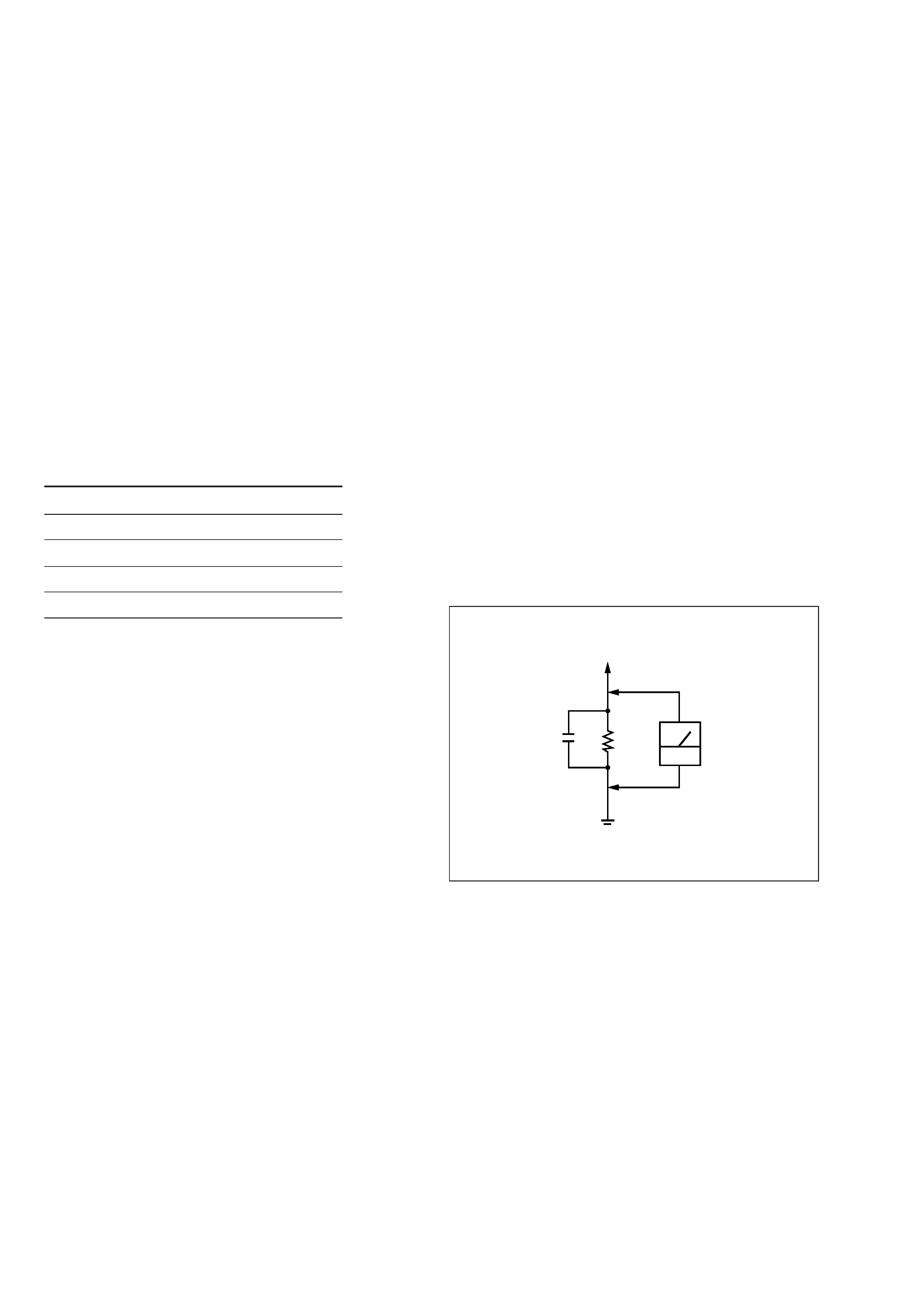
To Exposed Metal
Parts on Set
0.15
µF
1.5k
AC
voltmeter
(0.75V)
Earth Ground
Fig. A. Using an AC voltmeter to check AC leakage.
SAFETY CHECK-OUT
After correcting the original service problem, perform the follow-
ing safety check before releasing the set to the customer:
Check the antenna terminals, metal trim, "metallized" knobs, screws,
and all other exposed metal parts for AC leakage. Check leakage as
described below.
LEAKAGE TEST
The AC leakage from any exposed metal part to earth ground and
from all exposed metal parts to any exposed metal part having a
return to chassis, must not exceed 0.5 mA (500 microampers).
Leakage current can be measured by any one of three methods.
1. A commercial leakage tester, such as the Simpson 229 or RCA
WT-540A. Follow the manufacturers' instructions to use these
instruments.
2. A battery-operated AC milliammeter. The Data Precision 245
digital multimeter is suitable for this job.
3. Measuring the voltage drop across a resistor by means of a VOM
or battery-operated AC voltmeter. The "limit" indication is 0.75
V, so analog meters must have an accurate low-voltage scale.
The Simpson 250 and Sanwa SH-63Trd are examples of a pas-
sive VOM that is suitable. Nearly all battery operated digital
multimeters that have a 2V AC range are suitable. (See Fig. A)
3
TABLE OF CONTENTS
1. GENERAL
1-1. Location of Controls ........................................................... 4
2. DISASSEMBLY
2-1. Front Panel Assy ................................................................. 5
2-2. Mechanism Deck ................................................................. 5
2-3. Fitting Base ......................................................................... 6
2-4. Capstan Motor, Reel Motor ................................................. 6
2-5. Head Deck Assy .................................................................. 7
3. MECHANICAL ADJUSTMENTS ................................. 8
4. ELECTRICAL ADJUSTMENTS ................................... 8
5. DIAGRAMS
5-1. IC Pin Description ............................................................. 12
5-2. Circuit Boards Location .................................................... 14
5-3. Printed Wiring Boards Main Section ............................ 15
5-4. Schematic Diagram Main Section (1/4) ........................ 17
5-5. Schematic Diagram Main Section (2/4) ........................ 19
5-6. Schematic Diagram Main Section (3/4) ........................ 21
5-7. Schematic Diagram Main Section (4/4) ........................ 23
5-8. Printed Wiring Boards Power Section ........................... 25
5-9. Schematic Diagram Power Section ............................... 26
5-10. Printed Wiring Boards Panel Section ............................ 27
5-11. Schematic Diagram Panel Section ................................ 29
5-12. Printed Wiring Boards Deck A Section ......................... 31
5-13. Schematic Diagram Deck A Section ............................. 32
5-14. Printed Wiring Boards Deck B Section ......................... 33
5-15. Schematic Diagram Deck B Section ............................. 34
5-16. Printed Wiring Board
DOLBY-S Section (TC-WE825S only) ........................ 35
5-17. Schematic Diagram
DOLBY-S Section (TC-WE825S only) ........................ 35
6. EXPLODED VIEWS
6-1. Case Section ...................................................................... 38
6-2. Chassis Section ................................................................. 39
6-3. Cassette Holder Section .................................................... 40
6-4. Front Panel Section ........................................................... 41
6-5. Tape Mechanism Section 1 ............................................... 42
6-6. Tape Mechanism Section 2 ............................................... 43
7. ELECTRICAL PARTS LIST ........................................ 44
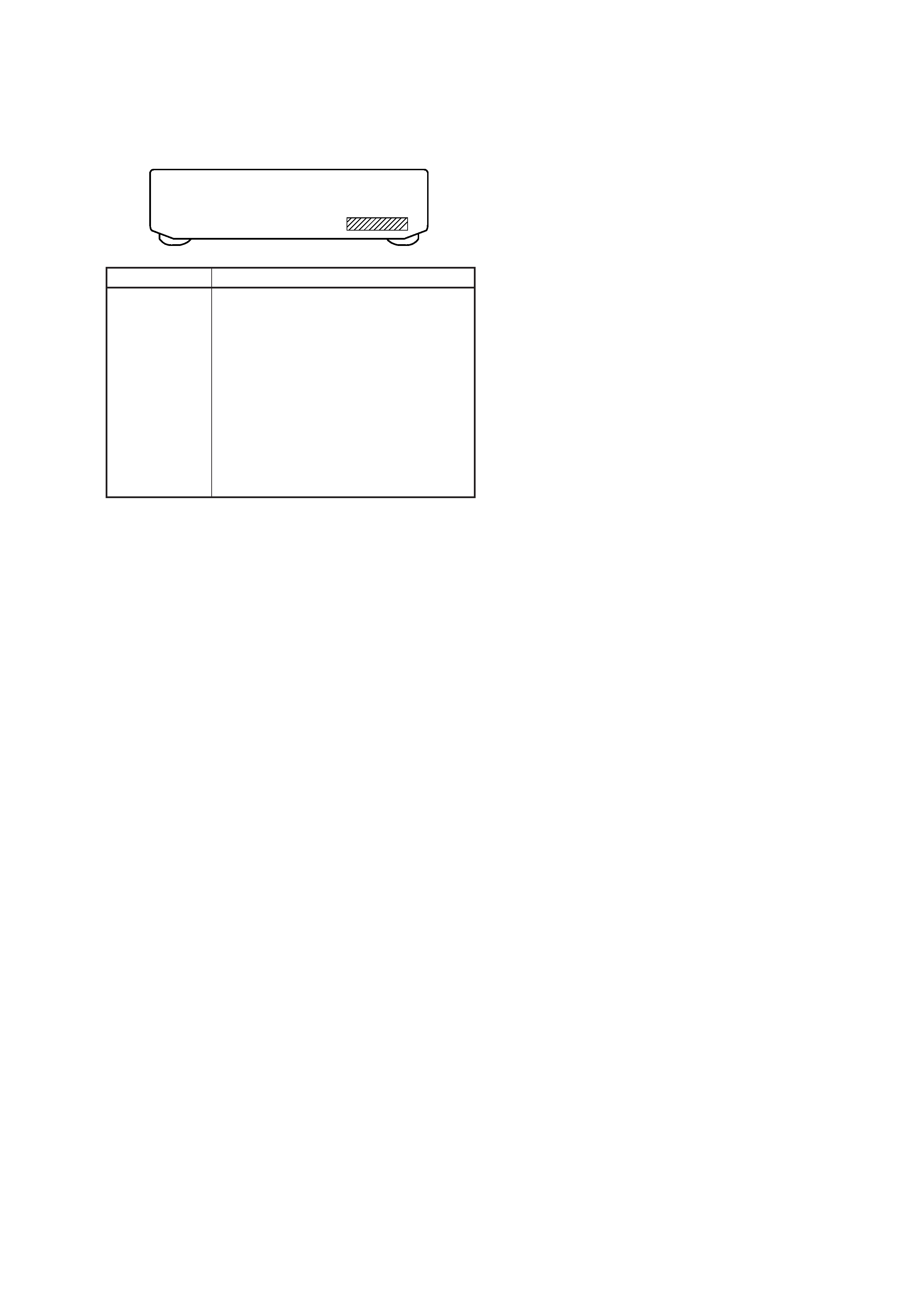
MODEL IDENTIFICATION
Back panel
Part No.
Part No.
Model
3-021-228-0
TC-WE625
: US model
3-021-228-1
TC-WE625
: CND model
3-021-228-2
TC-WE625
: AUS model
3-021-228-3
TC-WE625
: SP, MY model
3-021-228-4
TC-WE625
: CH model
3-021-242-0
TC-WE725
: AEP model
3-021-242-1
TC-WE725
: UK model
3-021-243-0
TC-WE825S : AEP model
3-021-243-1
TC-WE825S : UK model
3-021-243-3
TC-WE825S : US model
· Abbreviation
CND : Canadian model
AUS : Austrarian model
SP
: Singapore model
MY
: Malaysia model
CH
: Chinese model
4
SECTION 1
GENERAL
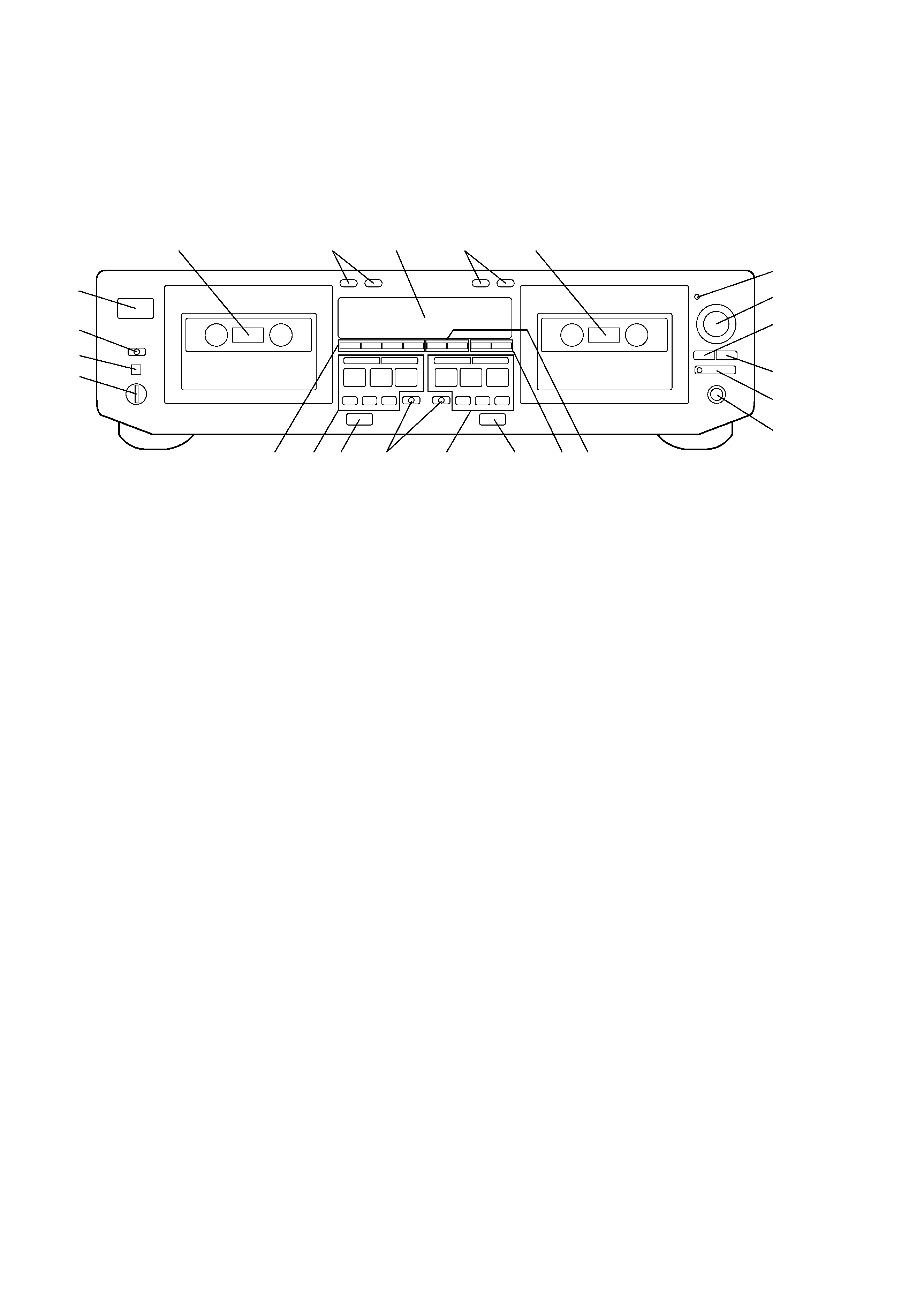
1-1. LOCATION OF CONTROLS
1
2
3
4
56
10
7
9
8
23
22
21
20
19
18
11
14
12
13
15
16 17
1.
1/u (Power) button (US, Canadian)
U (Power) button (EXCEPT US, Canadian)
2. DIRECTION MODE switch
3. PITCH CONTROL (
Ø ON/ø OFF) switch
(TC-WE725/WE825S)
4. PITCH CONTROL knob (TC-WE725/WE825S)
5. Cassette holder (Deck A)
6. COUNTER A buttons (Deck A)
RESET button
MEMORY button
7. Display window
8. COUNTER B buttons (Deck B)
RESET button
MEMORY button
9. Cassette holder (Deck B)
10. RMS buttons
RMS/START button
SET button
CHECK button
DISPLAY button
11. Tape operation buttons (Deck A)
0 (AMS), RMS - button
) (AMS), RMS + button
p CLEAR (Stop) button
ª BACK (Reverse play) button
· FRONT (Foward play) button
P PAUSE button
R REC MUTING button
r REC button
12.
§ (Eject) button (Deck A)
13. DOLBY NR switches
ON, OFF, FILTER switch
B, C, S switch ("S" use for TC-WE825S)
14. Tape operation buttons (Deck B)
0 (AMS) button
) (AMS) button
p (Stop) button
ª (Reverse play) button
· (Foward play) button
P PAUSE button
R REC MUTING button
r REC button
15.
§ (Eject) button (Deck B)
16. START (DECK B
P) buttons
A+B REC button
HIGH/NORMAL, DUBBING A
nB button
17. AUTO CAL (START
P) buttons
DECK A button
DECK B button
18. PHONES jack
19. SYNCHRO button and indicator
20. ARL button
21. FADER button
22. REC LEVEL knob
23. AUTO indicator
5
SECTION 2
DISASSEMBLY
Note : Follow the disassembly procedure in the numerical order given.
CASE
Unscrew the five case attachment screws M3
× 8 and remove
the case.
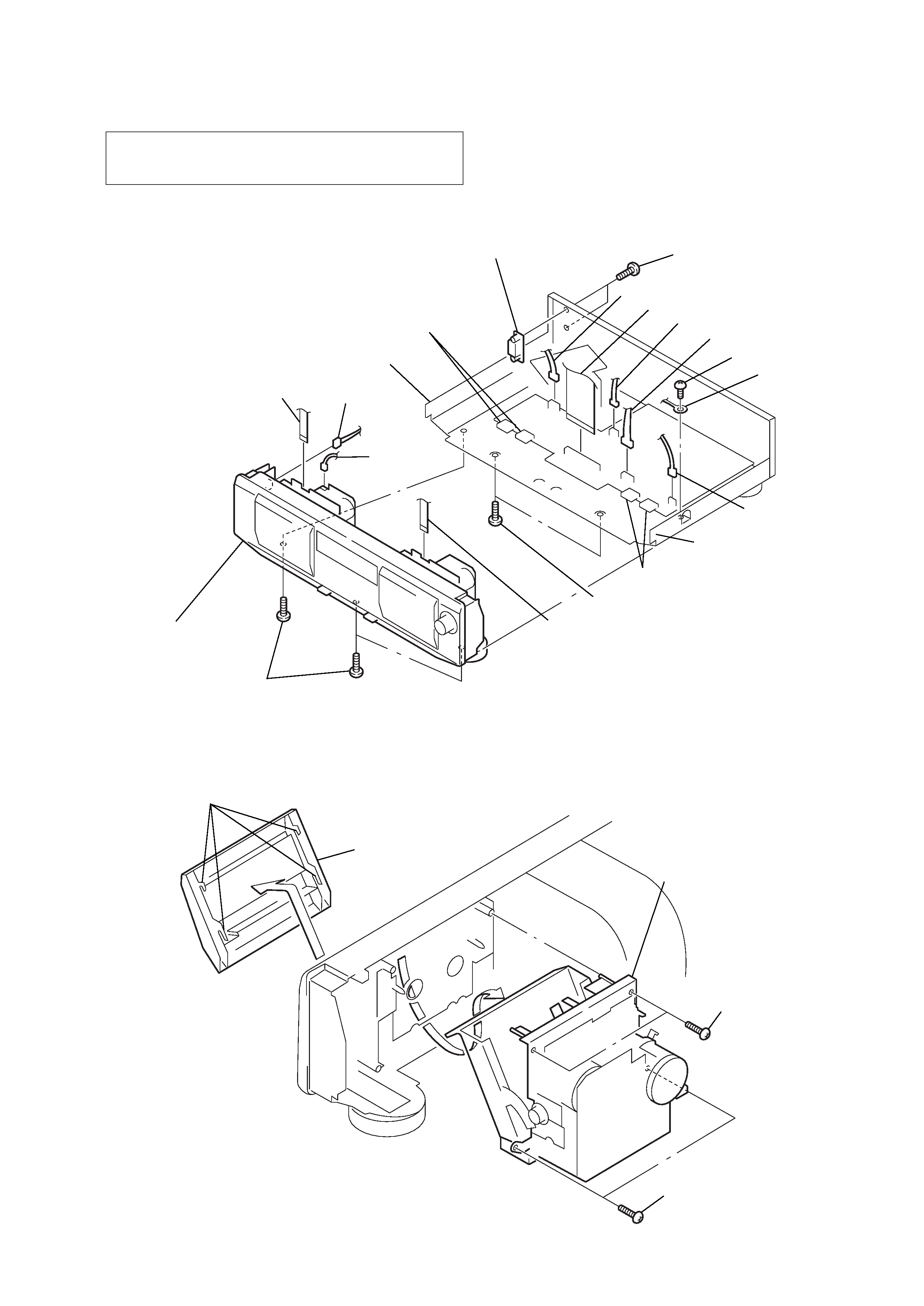
2-1. FRONT PANEL ASSY
1 BVTP 3x8
2 lug plate
3 CNA807
1 BVTP 3x8
2 power voltage selector
4 CNS802
5 CNA801 (US, Canadian)
6 CNA803
7 CNA806
8 CN51
0 CN002
!¡ CNP73
!¢ claw
!§ CN501, 502
!TM BVTP 3x6
! claw
!¶ CN503, 504
!£ BVTP 3x8
!· front panel assy
9 CN51
(WE725/WE825S)
5 BVTP 2.6x8
4 BVTP 2.6x8
6 mechanism deck
3 cassette lid
2 claws
2-2. MECHANISM DECK
1 Press the EJECT button.
POWER VOLTAGE SELECTOR
1 - 2 (Singapore, Malaysia)
FRONT PANEL ASSY 1 - !¶