Model Name Using Similar Mechanism
TC-WE435
DECK A
TCM-230ASR41A
DECK B
TCM-230ASR41B
US Model
Canadian Model
AEP Model
UK Model
E Model
Australian Model
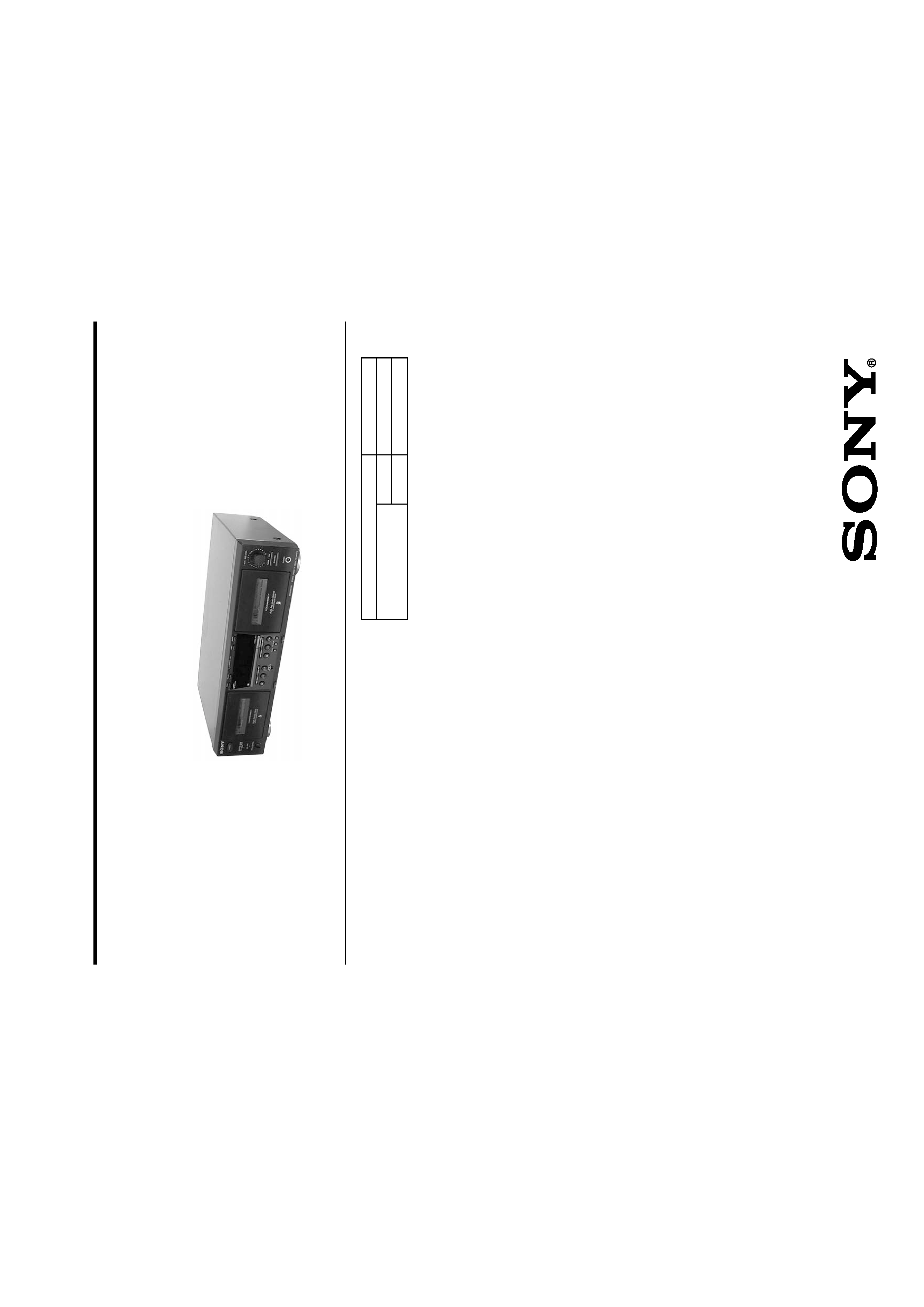
STEREO CASSETTE DECK
SPECIFICATIONS
Dolby noise reduction extension manufactured under license
from Dolby Laboratories Licensing Corporation.
HX Pro originated by Bang & Olufsen. "DOLBY", the double-D
symbol ; and "HX PRO" are trademarks of Dolby Laboratories
Licensing Corporation.
TC-WE475
-- Continued on next page --
Transport Mechanism Type
Ver. 1.6 2005.11
Sony Corporation
Home Audio Division
Pubulished by Sony Engineering Corporation
9-873-893-17
2005K02-1
© 2005.11
SERVICE MANUAL
System
Fast-winding time
Approx.100 sec. (with Sony C-60 cassette)
Signal-to-noise ratio (at peak level and weighted with Dolby
NR off)
55 dB, using Sony TYPE I cassette
57 dB, using Sony TYPE II cassette
58 dB, using Sony TYPE IV cassette
S/N ratio improvement
With Dolby B NR on:
Approx. 5 dB at 1 kHz, 10 dB at 5 kHz
With Dolby C NR on:
Approx. 15 dB at 500 Hz, 20 dB at 1 kHz
Harmonic distortion
0.4% (using Sony TYPE Icassette):
160 nWb/m 315 Hz, 3rd H.D.)
1.8% (using Sony TYPE IV cassette):
250 nWb/m 315 Hz, 3rd H.D.)
Frequency response (DOLBY NR OFF)
30-16,000 Hz (
±3 dB, IEC), 20-17,000 Hz
(
±6 dB), using Sony TYPE I cassette
30-17,000 Hz (
±3 dB, IEC), 20-18,000 Hz
(
±6 dB), using Sony TYPE II cassette
30-19,000 Hz (
±3 dB, IEC), 20-20,000 Hz
(
±6 dB), 30-13,000 Hz (±3 dB, 4dB recording),
using Sony TYPE IV cassette
Wow and flutter
±0.15% W. Peak (IEC)
0.1% W. RMS (NAB)
±0.2% W. Peak (DIN)
Variable pitch range
Approx. 30 to +30 %
Inputs
Line inputs (phono jacks)
sensitivity 0.16 V, input impedance 47 kilohms
Outputs
Line outputs (phono jacks)
rated output level 0.5 V at a load impedance of
47 kilohms, load impedance over 10 kilohms
Headphones (stereo phone jack)
output level 0.25 mW at a load impedance of
32 ohms
2
TC-WE475
SAFETY-RELATED COMPONENT WARNING!!
COMPONENTS IDENTIFIED BY MARK 0 OR DOTTED LINE
WITH MARK 0 ON THE SCHEMATIC DIAGRAMS AND IN THE
PARTS LIST ARE CRITICAL TO SAFE OPERATION. RE-
PLACE THESE COMPONENTS WITH SONY PARTS WHOSE
PART NUMBERS APPEAR AS SHOWN IN THIS MANUAL OR
IN SUPPLEMENTS PUBLISHED BY SONY.
ATTENTION AU COMPOSANT AYANT RAPPORT
À LA SÉCURITÉ!!
LES COMPOSANTS IDENTIFIÉS PAR UNE MARQUE 0 SUR LES
DIAGRAMMES SCHÉMATIQUES ET LA LISTE DES PIÈCES SONT
CRITIQUES POUR LA SÉCURITÉ DE FONCTIONNEMENT. NE
REMPLACER CES COMPOSANTS QUE PAR DES PIÈCES SONY
DONT LES NUMÉROS SONT DONNÉS DANS CE MANUEL OU
DANS LES SUPPLÉMENTS PUBLIÉS PAR SONY.
SAFETY CHECK-OUT
After correcting the original service problem, perform the follow-
ing safety checks before releasing the set to the customer:
Check the antenna terminals, metal trim, "metallized" knobs, screws,
and all other exposed metal parts for AC leakage. Check leakage as
described below.
LEAKAGE
The AC leakage from any exposed metal part to earth Ground and
from all exposed metal parts to any exposed metal part having a
return to chassis, must not exceed 0.5 mA (500 microampers). Leak-
age current can be measured by any one of three methods.
1. A commercial leakage tester, such as the Simpson 229 or RCA
WT-540A. Follow the manufacturers' instructions to use these
instruments.
2. A battery-operated AC milliammeter. The Data Precision 245
digital multimeter is suitable for this job.
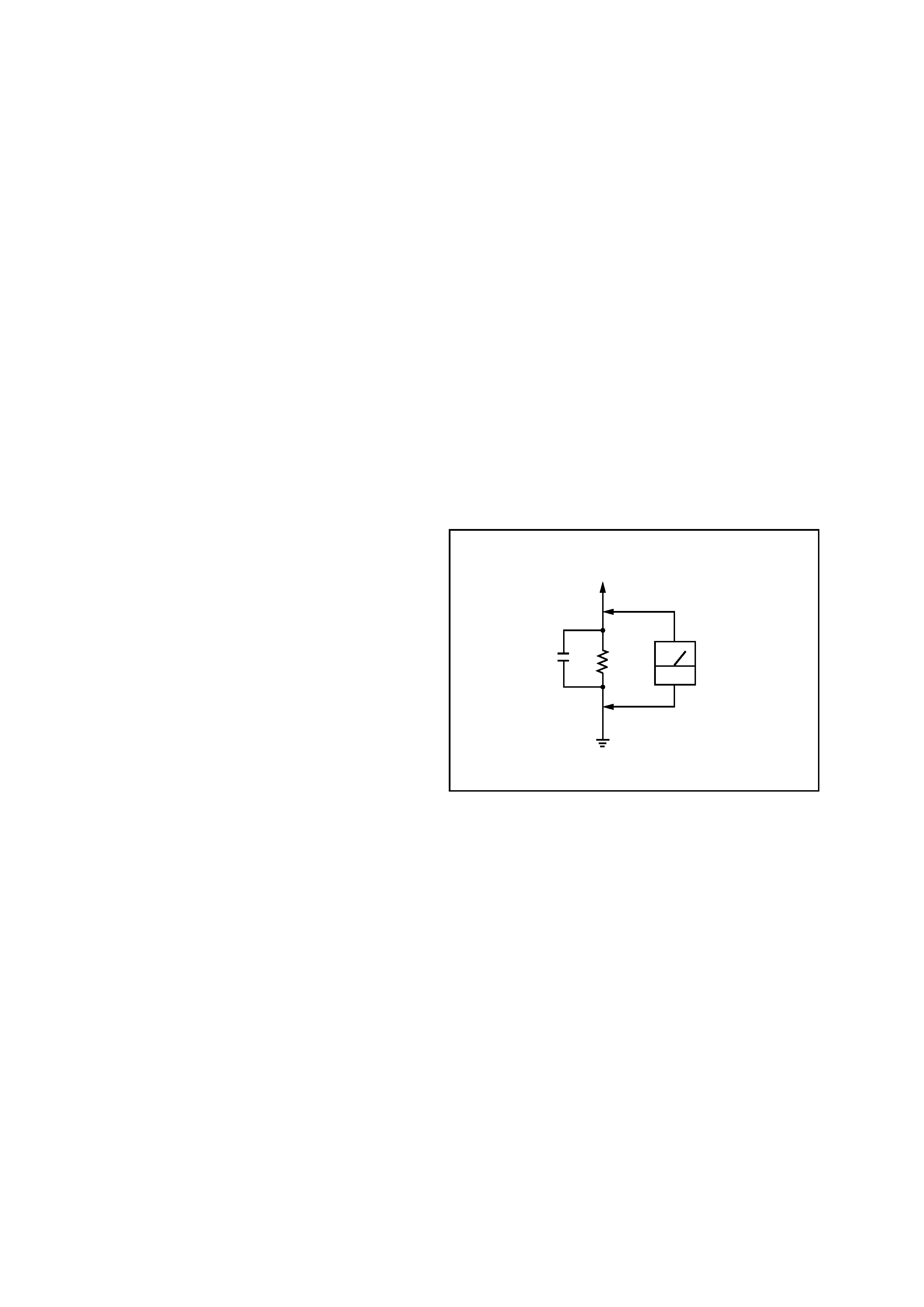
3. Measuring the voltage drop across a resistor by means of a VOM
or battery-operated AC voltmeter. The "limit" indication is 0.75
V, so analog meters must have an accurate low-voltage scale.
The Simpson 250 and Sanwa SH-63Trd are examples of a pas-
sive VOM that is suitable. Nearly all battery operated digital
multimeters that have a 2V AC range are suitable. (See Fig. A)
Fig. A. Using an AC voltmeter to check AC leakage.
0.15
µF
To Exposed Metal
Parts on Set
1.5k
AC
voltmeter
(0.75V)
Earth Ground
General
Power requirements
U.S.A.and Canadian models:
120 V AC, 60Hz
European models:
230 V AC, 50/60Hz
Australian models:
240 V AC, 50/60Hz
Other models:
120/220/230-240 V AC, 50/60Hz
Adjustable with voltage selector
Power consumption
18 watts
Dimensions (w/h/d)
Approx. 430
× 120 × 300 mm
Mass
4.2 kg
Supplied accessories
Audio connecting cords (2)
Control A1II cable (1)*
*Supplied for Canadian models only
Design and specifications are subject to change
without notice.
3
TC-WE475
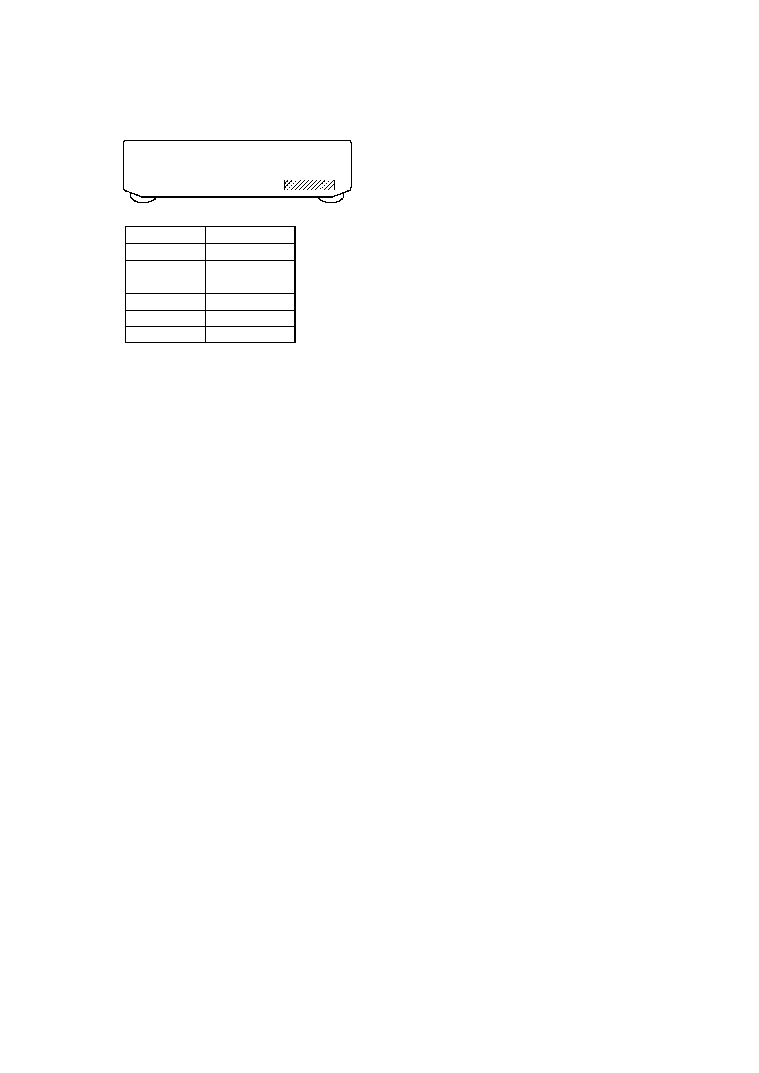
PARTS No.
MODEL
4-232-514-0s
US model
4-232-514-1s
CND model
4-232-514-2s
AEP model
4-232-514-3s
UK model
4-232-514-4s
SP model
4-232-514-5s
AUS model
MODEL IDENTIFICATION
Back panel
Part No.
· Abbreviation
CND : Canadian model
SP
: Singapore model
AUS : Australian model
TABLE OF CONTENTS
1. GENERAL .......................................................................... 4
2. DISASSEMBLY
2-1. Case ...................................................................................... 5
2-2. Front Panel Assy ................................................................... 5
2-3. Cassette Lid Assy (Deck A/B) .............................................. 6
2-4. Mechanism Deck Assy (Deck A/B) ...................................... 6
3. SERVICE MODE .............................................................. 7
4. MECHANICAL ADJUSTMENTS ................................. 8
5. ELECTRICAL ADJUSTMENTS ................................. 8
6. DIAGRAMS
6-1. Circuit Boards Location ...................................................... 12
6-2. Printed Wiring Board MAIN Section ............................ 14
6-3. Schematic Diagram MAIN (1/4) Section ...................... 15
6-4. Schematic Diagram MAIN (2/4) Section ...................... 16
6-5. Schematic Diagram MAIN (3/4) Section ...................... 17
6-6. Schematic Diagram MAIN (4/4) Section ...................... 18
6-7. Printed Wiring Board DECK A Section ........................ 19
6-8. Schematic Diagram DECK A Section ........................... 19
6-9. Printed Wiring Board DECK B Section ........................ 19
6-10. Schematic Diagram DECK B Section ......................... 19
6-11. Schematic Diagram DISPLAY Section ....................... 20
6-12. Printed Wiring Board DISPLAY Section .................... 21
6-13. Schematic Diagram PANEL Section ........................... 22
6-14. Printed Wiring Board PANEL Section ........................ 23
6-15. Schematic Diagram POWER Section ......................... 24
6-16. Printed Wiring Board POWER Section ...................... 25
6-17. IC PIN FUNCTION .......................................................... 26
7. EXPLODED VIEWS
7-1. Case Section ........................................................................ 27
7-2. Chassis Section ................................................................... 28
7-3. Cassette Holder Section ...................................................... 29
7-4. Front Panel Section ............................................................. 30
7-5. Tape Mechanism Section .................................................... 31
8. ELECTRICAL PARTS LIST ........................................ 32
4
TC-WE475
SECTION 1
GENERAL
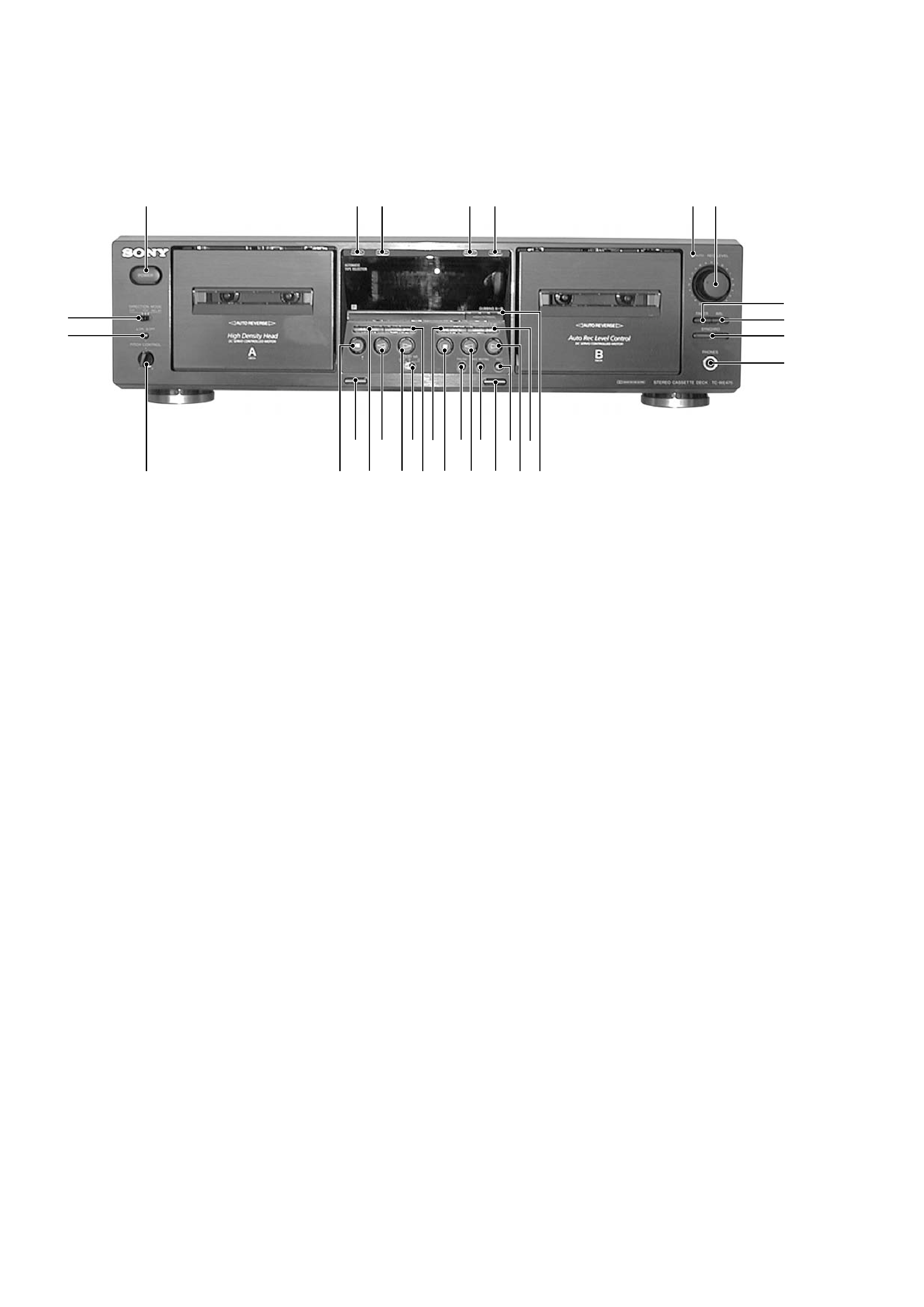
Front Panel
Location of Parts and Controls
1
POWER button
2
RESET (Deck A) button
3
MEMORY (Deck A) button
4
RESET (Deck B) button
5
MEMORY (Deck B) button
6
AUTO REC LEVEL indicator
7
REC LEVEL knob
8
FADER button
9
ARL button
q;
SYNCHRO button
qa
PHONES jack
qs
HIGH/NOMAL button
qd
(AMS) M (Deck B) button
qf
H (Deck B) button
qg
REC z button
qh
A (Eject) (Deck B) button
qj
REC MUTING W button
qk
h (Deck B) button
ql
PAUSE X button
w;
x (Deck B) button
wa
m (AMS) (Deck B) button
ws
(AMS) M (Deck A) button
wd
DOLBY NR OFF B/C switch
wf
H (Deck A) button
wg
h (Deck A) button
wh
m (AMS) (Deck A) button
wj
A (Eject) (Deck A) button
wk
x (Deck A) button
wl
PITCH CONTROL knob
e;
PITCH CONTROL button
ea
DIRECTION MODE switch
· AMS is the abbreviation for Automatic Music Sensor.
1
2 3
4 5
6 7
e;
ea
wj
wl
ql qj
wg
wd
wf
w; qk qh
wh
9
0
qa
8
ws
qs
qd
qf
wk
qg
wa
5
TC-WE475
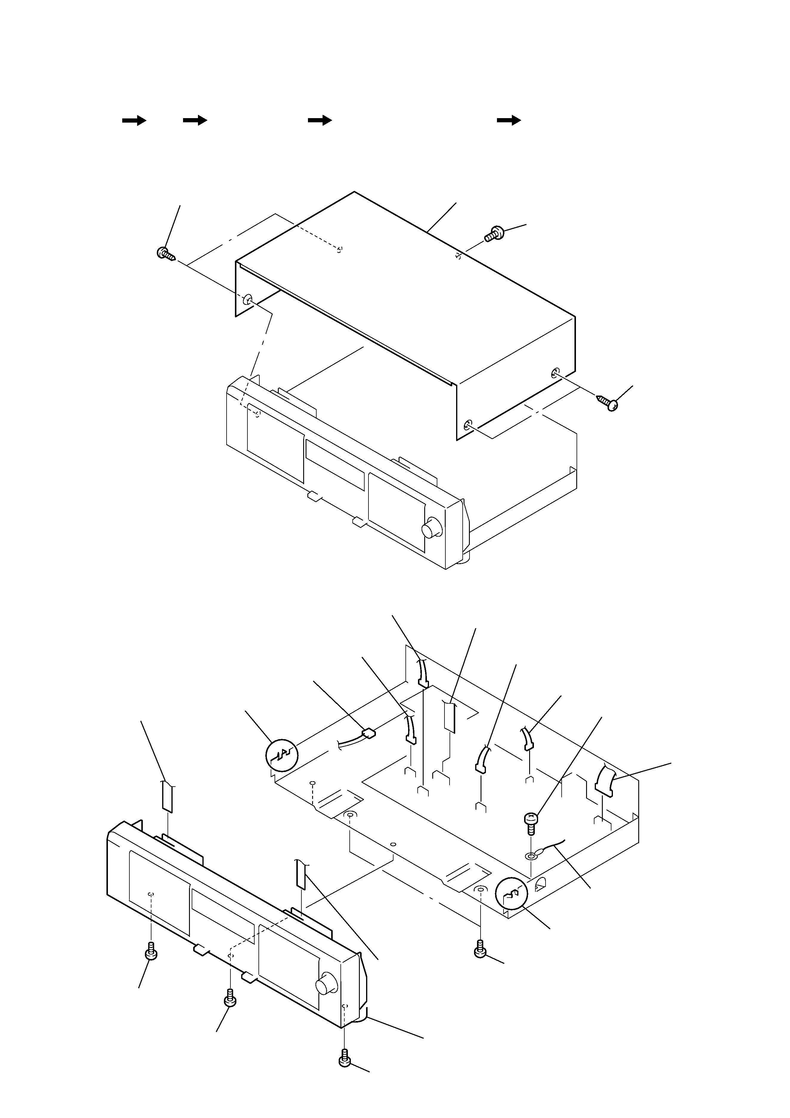
SECTION 2
DISASSEMBLY
Note : Follow the disassembly procedure in the numerical order given.
2-1. CASE
2-2. FRONT PANEL ASSY
1
screw
(BVTT 3x6)
2
two screws
(case 3 TP2)
3
two screws
(case 3 TP2)
4
case
qs
screw
(BVTP 3x8)
qf
screw
(BVTP 3x8)
qd
screw
(BVTP 3x8)
qg
two screws
(BVTT 3x6)
qj
claw
qh
claw
qk
front panel assy
8
CN301
7
CN401
2
CN807
1
CN5802
3
CN803
4
CNA806
5
flat type wire
(Deck A)
9
CN002
6
flat type wire
(Deck B)
0
screw
(BVTP 3x8)
qa
wire
Set
Case
Front Panel Assy
Cassette Lid Assy (Deck A/B)
Mechanism Deck Assy (Deck A/B)
· The equipment can be removed using the following procedure.