
Stereo
Cassette Deck
© 2001 Sony Corporation
Operating Instructions
4-232-596-12 (1)
TC-WE675
TC-WE475
2
Warning
To prevent fire or shock hazard, do not
expose the unit to rain or moisture.
To prevent fire, do not cover the ventilation of the
apparatus with news papers, table-cloths, curtains,
etc. And don't place lighted candles on the apparatus.
To prevent fire or shock hazard, do not place objects
filled with liquids, such as vases, on the apparatus.
Do not install the appliance in a confined space,
such as a bookcase or built-in cabinet.
Don't throw a battery, dispose it as the
injurious wastes.
NOTICE FOR THE CUSTOMERS IN THE
U.S.A.
This symbol is intended to alert the
user to the presence of uninsulated
"dangerous voltage" within the
product's enclosure that may be of
sufficient magnitude to constitute a
risk of electric shock to persons.
This symbol is intended to alert the
user to the presence of important
operating and maintenance
(servicing) instructions in the
literature accompanying the
appliance.
Owner's Record
The model and serial numbers are located on the rear
panel of the unit. Record the serial number in the
space provided below. Refer to them whenever you
call upon your Sony dealer regarding this product.
Model No. ___________
Serial No. ___________
INFORMATION
This equipment has been tested and found to comply
with the limits for a Class B digital device, pursuant
to Part 15 of the FCC Rules. These limits are
designed to provide reasonable protection against
harmful interference in a residential installation. This
equipment generates, uses, and can radiate radio
frequency energy and, if not installed and used in
accordance with the instructions, may cause harmful
interference to radio communications. However,
there is no guarantee that interference will not occur
in a particular installation. If this equipment does
cause harmful interference to radio or television
reception, which can be determined by turning the
equipment off and on, the user is encouraged to try to
correct the interference by one or more of the
following measures:
-- Reorient or relocate the receiving antenna.
-- Increase the separation between the equipment and
receiver.
-- Connect the equipment into an outlet on a circuit
different from that to which the receiver is
connected.
-- Consult the dealer or an experienced radio/TV
technician for help.
CAUTION
You are cautioned that any changes or modification
not expressly approved in this manual could void
your authority to operate this equipment.
NOTICE FOR THE CUSTOMERS IN
CANADA
CAUTION:
TO PREVENT ELECTRIC SHOCK, DO NOT USE
THIS POLARIZED AC PLUG WITH AN
EXTENSION CORD, RECEPTACLE OR OTHER
OUTLET UNLESS THE BLADES CAN BE FULLY
INSERTED TO PREVENT BLADE EXPOSURE.
About this manual
The instructions in this manual are for models
TC-WE675 and WE475. Check your model number
by looking at the rear panel of your tape deck. In this
manual, the TC-WE675 is the model used for
illustration purposes. Any difference in operation is
clearly indicated in the text, for example,
"TC-WE675 only."

3
Table of Contents
Parts Identification
Main unit ............................................... 4
Getting Started
Hooking up the system .......................... 6
Playing a Tape
Playing a tape ........................................ 7
Locating a track
-- Multi-AMS/Auto Play/
Memory Play ................................... 8
Creating your own program
-- RMS Play (TC-WE675 only) ..... 8
Recording on a Tape
Recording on a tape ............................. 10
Adjusting bias and recording level
calibration automatically
(TC-WE675 only) ......................... 11
Adjusting the recording level
automatically
-- Auto Rec Level ......................... 12
Fading in and out -- Fader .................. 13
Dubbing a tape ..................................... 14
Recording on both decks in succession
-- Relay Recording
(TC-WE675 only) ......................... 15
Recording the same source on both decks
-- Simultaneous Recording
(TC-WE675 only) ......................... 15
Recording your own program
-- RMS Dubbing
(TC-WE675 only) ......................... 16
Inserting a blank space during recording
-- Record Muting ......................... 16
Using the CONTROL A1II control
system ............................................ 17
Additional Information
Precautions .......................................... 20
Troubleshooting ................................... 22
Specifications ...................................... 23
4
Parts Identification
The items are arranged in alphabetical order.
Refer to the pages indicated in parentheses ( ) for details.
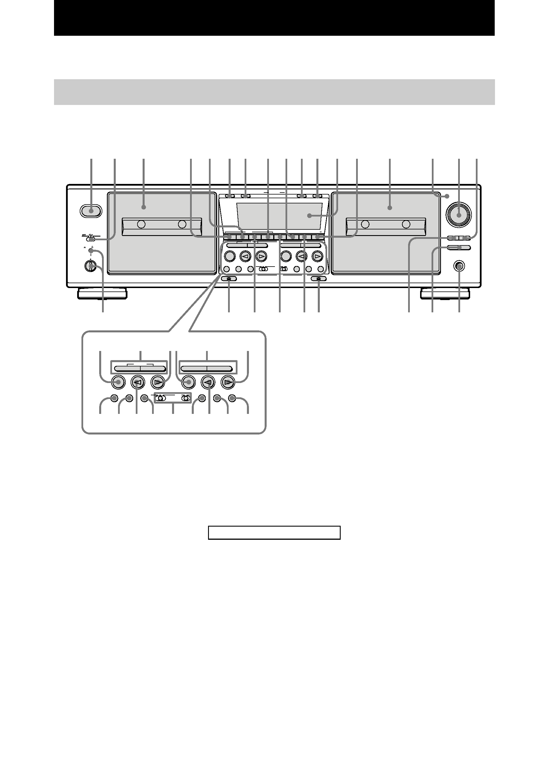
Main unit
TC-WE675
12
3
4 5 6 7
8 9 0 qa qs
qd
qk
ql
w;
wa
ws
wd
wf
wh
wg
qf
qg
qh qj
wk
wj
wl e;
ea
es
ra r; el
eh
ej
ek
eg ef
ed
x
XW
z
XW
z
M
mM
m
x
PHONES
AUTO REC LEVEL
FADER
ARL
SYNCHRO
RESET
MEMORY
RESET
MEMORY
COUNTER
AB
5
0
10
19
28
37
46
·
·
·
·
·
·
·
·
·
·
DIRECTION MODE
PITCH CONTROL
POWER
ON
OFF
RELAY
+
(AMS)(AMS)
CLEAR
RMS/START
SET
RMS
AUTO CAL ( START X)
DUBBING A B
CHECK
DISPLAY
DECK A
DECK B
A+B REC
HIGH/NORMAL
RMS +
PAUSE
REC MUTING
REC
PAUSE
REC MUTING
REC
OFF
DOLBY NR
ON ON FILTER
BACK
FRONT
BC
(AMS)(AMS)
START (DECK B X)
x
XW
z
XW
z
M
mM
m
x
(AMS)(AMS)
CLEAR
RMS +
PAUSE
REC MUTING
REC
PAUSE
REC MUTING
REC
OFF
DOLBY NR
ON ON FILTER
BACK
FRONT
BC
(AMS)(AMS)
START (DECK B X)
A + B REC ws (15)
ARL qj (12)
AUTO indicator qg (10, 12)
CHECK wf (9)
Deck A 3 (7, 20)
DECK A wd (11)
Deck B qf (10, 20)
DECK B 9 (11)
DIRECTION MODE 2 (7, 10)
Display qs
DISPLAY 8 (9)
DOLBY NR ej (7, 10)
FADER w; (13)
HIGH/NORMAL qd (14)
MEMORY (on deck A) 7 (8)
MEMORY (on deck B) qa (8)
PHONES jack qk
PITCH CONTROL wh (7)
POWER 1 (7, 10)
REC LEVEL qh (11, 12)
RESET (on deck A) 6 (8)
RESET (on deck B) q; (8)
RMS/START 4 (8, 16)
SET 5 (9)
SYNCHRO ql (18)
BUTTON DESCRIPTIONS
A (eject on deck B) wa (7, 10, 21)
A (eject on deck A) wg (7, 10, 21)
x (stop on deck A)/CLEAR wj (7,
9, 10, 12)
M (go forward)/AMS/RMS +/m
(go back)/AMS/RMS (on deck
A) wk (7, 8)
H (play on deck A)/FRONT wl (7,
8, 10, 11)
x (stop on deck B) e; (7, 10, 12)
M (go forward)/AMS/m (go
back)/AMS (on deck B) ea (7, 8)
H (play on deck B) es (7, 10, 11)
z REC (on deck B) ed (10)
W REC MUTING (on deck B) ef
(16)
h (reverse play on deck B) eg (7,
10, 11)
X PAUSE (on deck B) eh (7, 10,
11)
z REC (on deck A) ek (10)
h (reverse play on deck A)/BACK
el (7, 8, 10, 11)
W REC MUTING (on deck A) r;
(16)
X PAUSE (on deck A) ra (7, 10,
11)
Parts
Identification
5
12
3
5
47 8
69
0
qg
qh
qj
w;
qk
ql
wa
ws
wd
ea
wl
e;
wh
wj
wg wf
wk
qa
qs
qd qf
DUBBING A B
x
XW
z
M
mM
m
x
PHONES
AUTO REC LEVEL
FADER
ARL
SYNCHRO
RESET
MEMORY
RESET
MEMORY
COUNTER
AB
5
0
10
19
28
37
46
·
·
·
·
·
·
·
·
·
·
DIRECTION MODE
PITCH CONTROL
POWER
RELAY
+
(AMS)(AMS)
CLEAR
HIGH/NORMAL
PAUSE
REC MUTING
REC
OFF
DOLBY NR
BACK
FRONT
BC
(AMS)(AMS)
ON
OFF
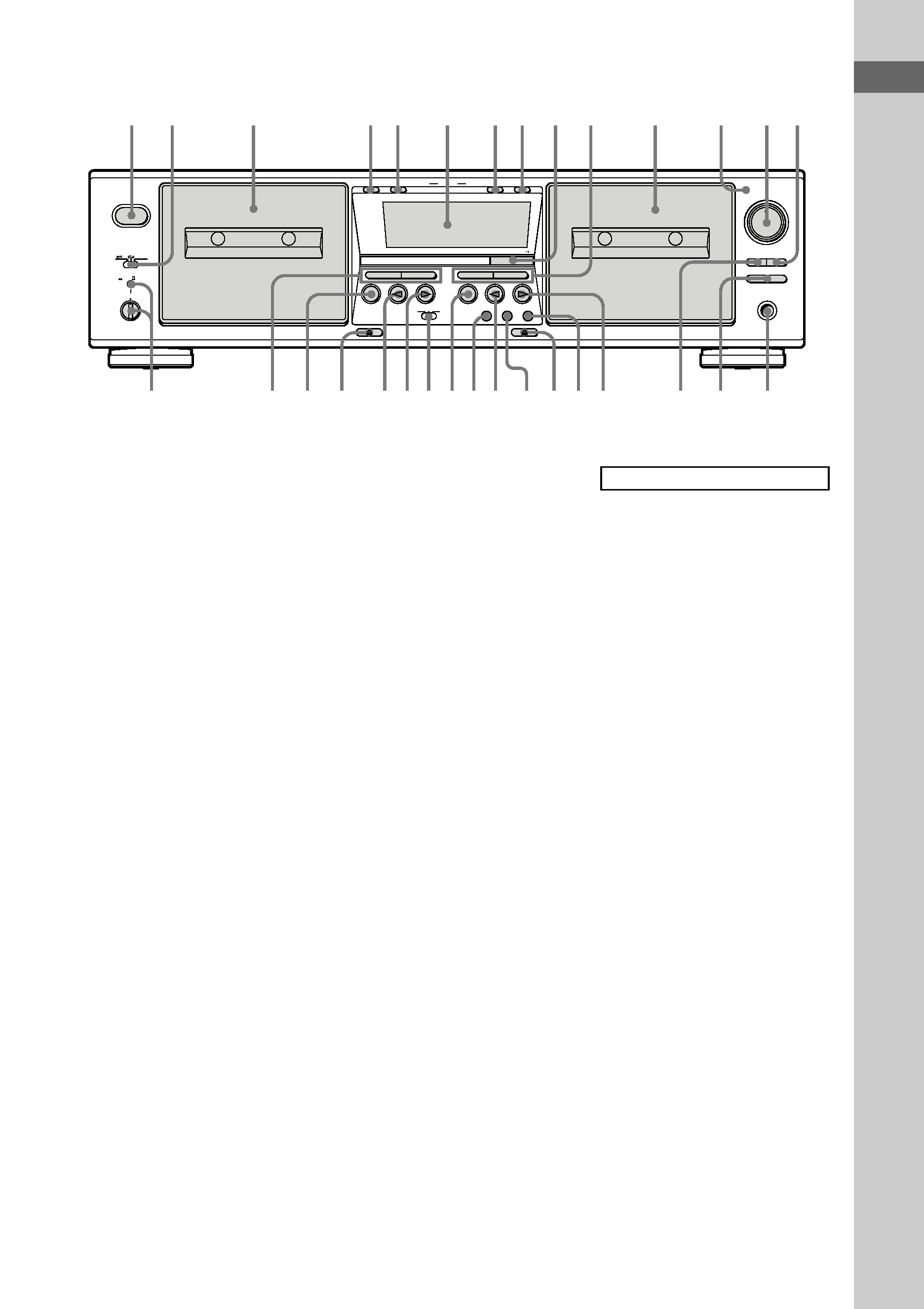
TC-WE475
ARL qf (12)
AUTO indicator qs (10, 12)
Deck A 3 (7, 20)
Deck B qa (10, 20)
DIRECTION MODE 2 (7, 10)
Display 6
DOLBY NR wg (7, 10)
FADER qj (13)
HIGH/NORMAL 9 (14)
MEMORY (on deck A) 5 (8)
MEMORY (on deck B) 8 (8)
PHONES jack qg
PITCH CONTROL ea (7)
POWER 1 (7, 10)
REC LEVEL qd (11, 12)
RESET (on deck A) 4 (8)
RESET (on deck B) 7 (8)
SYNCHRO qh (18)
BUTTON DESCRIPTIONS
M (go forward)/AMS/m (go
back)/AMS (on deck B) q; (7, 8)
H (play on deck B) qk (7, 10)
z REC (on deck B) ql (10)
A (eject on deck B) w; (7, 10, 21)
W REC MUTING (on deck B) wa
(16)
h (reverse play on deck B) ws (7,
10)
X PAUSE (on deck B) wd (7)
x (stop on deck B) wf (7, 10)
H (play on deck A) wh (7)
h (reverse play on deck A) wj (7)
A (eject on deck A) wk (7)
x (stop on deck A) wl (7)
M (go forward)/AMS /m (go
back)/AMS (on deck A) e; (7, 8)