1
Model Name Using Similar Mechanism
TC-WE425/WE525/WR681
DECK A
TCM-230ASR3/HSR3
DECK B
TCM-230ASR4/HSR4
SERVICE MANUAL
US Model
Canadian Model
AEP Model
UK Model
E Model
Australian Model
Chinese Model
STEREO CASSETTE DECK
SPECIFICATIONS
Dolby noise reduction extension manufactured under license
from Dolby Laboratories Licensing Corporation.
HX Pro originated by Bang & Olufsen. "DOLBY", the double-D
symbol
a and "HX PRO" are trademarks of Dolby Laboratories
Licensing Corporation.
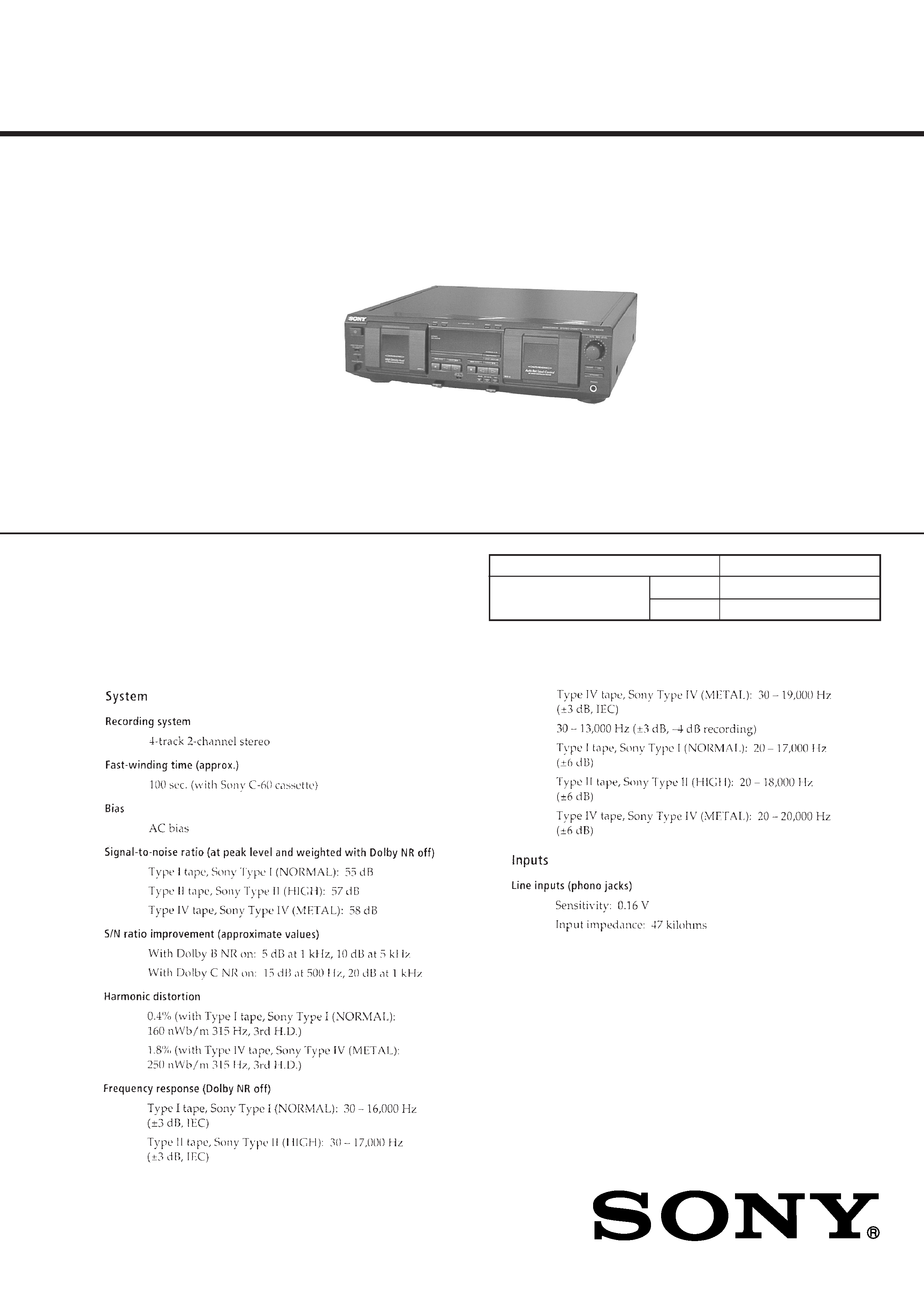
TC-WE435
-- Continued on next page --
Transport Mechanism Type
Ver 1.1 2001. 05
9-928-829 -12
2001E0200-1
© 2001.5
Sony Corporation
Personal Audio Company
Shinagawa Tec Service Manual Production Group
2
SAFETY-RELATED COMPONENT WARNING!!
COMPONENTS IDENTIFIED BY MARK
! OR DOTTED LINE
WITH MARK
! ON THE SCHEMATIC DIAGRAMS AND IN
THE PARTS LIST ARE CRITICAL TO SAFE OPERATION.
REPLACE THESE COMPONENTS WITH SONY PARTS WHOSE
PART NUMBERS APPEAR AS SHOWN IN THIS MANUAL OR
IN SUPPLEMENTS PUBLISHED BY SONY.
ATTENTION AU COMPOSANT AYANT RAPPORT
À LA SÉCURITÉ!!
LES COMPOSANTS IDENTIFIÉS PAR UNE MARQUE
! SUR LES
DIAGRAMMES SCHÉMATIQUES ET LA LISTE DES PIÈCES SONT
CRITIQUES POUR LA SÉCURITÉ DE FONCTIONNEMENT. NE
REMPLACER CES COMPOSANTS QUE PAR DES PIÈCES SONY
DONT LES NUMÉROS SONT DONNÉS DANS CE MANUEL OU
DANS LES SUPPLÉMENTS PUBLIÉS PAR SONY.
SAFETY CHECK-OUT
After correcting the original service problem, perform the follow-
ing safety checks before releasing the set to the customer:
Check the antenna terminals, metal trim, "metallized" knobs, screws,
and all other exposed metal parts for AC leakage. Check leakage as
described below.
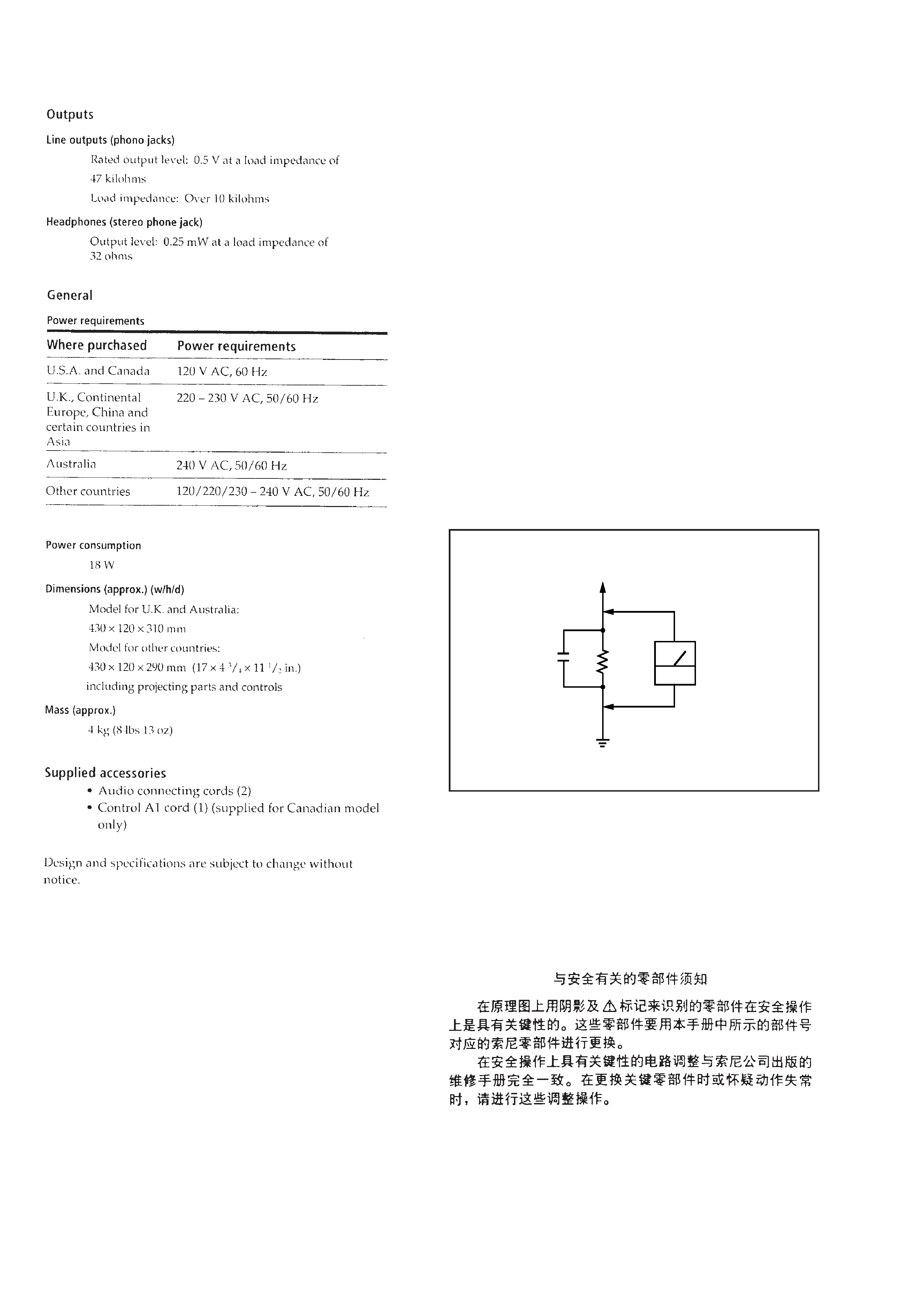
LEAKAGE
The AC leakage from any exposed metal part to earth Ground and
from all exposed metal parts to any exposed metal part having a
return to chassis, must not exceed 0.5 mA (500 microampers). Leak-
age current can be measured by any one of three methods.
1. A commercial leakage tester, such as the Simpson 229 or RCA
WT-540A. Follow the manufacturers' instructions to use these
instruments.
2. A battery-operated AC milliammeter. The Data Precision 245
digital multimeter is suitable for this job.
3. Measuring the voltage drop across a resistor by means of a VOM
or battery-operated AC voltmeter. The "limit" indication is 0.75
V, so analog meters must have an accurate low-voltage scale.
The Simpson 250 and Sanwa SH-63Trd are examples of a pas-
sive VOM that is suitable. Nearly all battery operated digital
multimeters that have a 2V AC range are suitable. (See Fig. A)
Fig. A. Using an AC voltmeter to check AC leakage.
0.15
µF
To Exposed Metal
Parts on Set
1.5k
AC
voltmeter
(0.75V)
Earth Ground
3
MODEL IDENTIFICATION
Back panel
Part No.
PARTS No.
MODEL
3-032-413-0
US model
3-032-413-1
CND model
3-032-413-2
AEP model
3-032-413-3
UK model
3-032-413-4
AUS model
3-032-413-5
SP, MY model
3-032-413-6
CH model
· Abbreviation
CND : Canadian model
SP
: Singapore model
MY
: Malaysia model
AUS : Australian model
CH
: Chinese model
TABLE OF CONTENTS
1. GENERAL .......................................................................... 4
2. DISASSEMBLY
2-1. Case ...................................................................................... 5
2-2. Front Panel Assembly ........................................................... 5
2-3. Cassette Lid Assembly (Deck A/B) ...................................... 6
2-4. Mechanism Deck Assembly (Deck A/B) .............................. 6
2-5. Leaf SW (PB) Board (Deck A),
Leaf SW (REC/PB) Board (Deck B) .................................... 7
2-6. Pinch Lever (FWD)/(REV) Assembly (Deck A/B) ............... 8
2-7. Flywheel (FWD)/(REV) Assembly (Deck A/B) ................... 8
2-8. Mechanical Block Assembly (Deck A/B) ............................. 9
2-9. Head Relay (PB) Board (Deck A),
Head Relay (REC/PB) Board (Deck B) ................................ 9
3. SERVICE MODE ............................................................ 10
4. MECHANICAL ADJUSTMENTS ............................... 11
5. ELECTRICAL ADJUSTMENTS ............................... 11
6. DIAGRAMS
6-1. Circuit Boards Location ...................................................... 15
6-2. Printed Wiring Board Main Section .............................. 17
6-3. Schematic Diagram Main Section (1/4) ........................ 19
6-4. Schematic Diagram Main Section (2/4) ........................ 21
6-5. Schematic Diagram Main Section (3/4) ........................ 23
6-6. Schematic Diagram Main Section (4/4) ........................ 25
6-7. Printed Wiring Board Deck A Section .......................... 27
6-8. Schematic Diagram Deck A Section ............................. 27
6-9. Printed Wiring Board Deck B Section .......................... 28
6-10. Schematic Diagram Deck B Section ........................... 28
6-11. Schematic Diagram Display Section ........................... 29
6-12. Printed Wiring Board Display Section ....................... 31
6-13. Schematic Diagram Panel Section .............................. 33
6-14. Printed Wiring Board Panel Section ........................... 35
6-15. Schematic Diagram Power Section ............................. 37
6-16. Printed Wiring Board Power Section ......................... 39
6-17. IC Pin Function ................................................................ 41
7. EXPLODED VIEWS
7-1. Case Section ........................................................................ 43
7-2. Chassis Section ................................................................... 44
7-3. Cassette Holder Section ...................................................... 45
7-4. Front Panel Section ............................................................. 46
7-5. Tape Mechanism Section
(Deck A: TCM-230ASR3/HSR3)
(Deck A: TCM-230ASR4/HSR4) ....................................... 47
8. ELECTRICAL PARTS LIST ........................................ 48
4
SECTION 1
GENERAL
LOCATION OF PARTS AND CONTROLS
1
U button
2
RESET (Deck A) button
3
MEMORY (Deck A) button
4
RESET (Deck B) button
5
MEMORY (Deck B) button
6
AUTO REC LEVEL indicator
7
REC LEVEL knob
8
FADER button
9
ARL button
10 SYNCHRO button
11 PHONES jack
12 HIGH/NOMAL button
13 (AMS)
) (Deck B) button
14
0 (AMS) (Deck B) button
15
· (Deck B) button
16
ª (Deck B) button
17 REC
r button
Front Panel
30
18
§ (Eject) (Deck B) button
19 REC MUTING
R button
20 PAUSE
P button
21
p (Deck B) button
22 DOLBY NR OFF B/C switch
23
· (Deck A) button
24
ª (Deck A) button
25
§ (Eject) (Deck A) button
26
p (Deck A) button
27 (AMS)
) (Deck A) button
28
0 (AMS) (Deck A) button
29 PITCH CONTROL knob
30 PITCH CONTROL button
31 DIRECTION switch
· AMS is the abbreviation for Automatic Music Sensor.
13
14
15
16
23
24
27
28
11
12
17
18
19
20
21
22
25
26
29
10
8
9
24
6
7
13
5
31
5
SECTION 2
DISASSEMBLY
Note : Follow the disassembly procedure in the numerical order given.
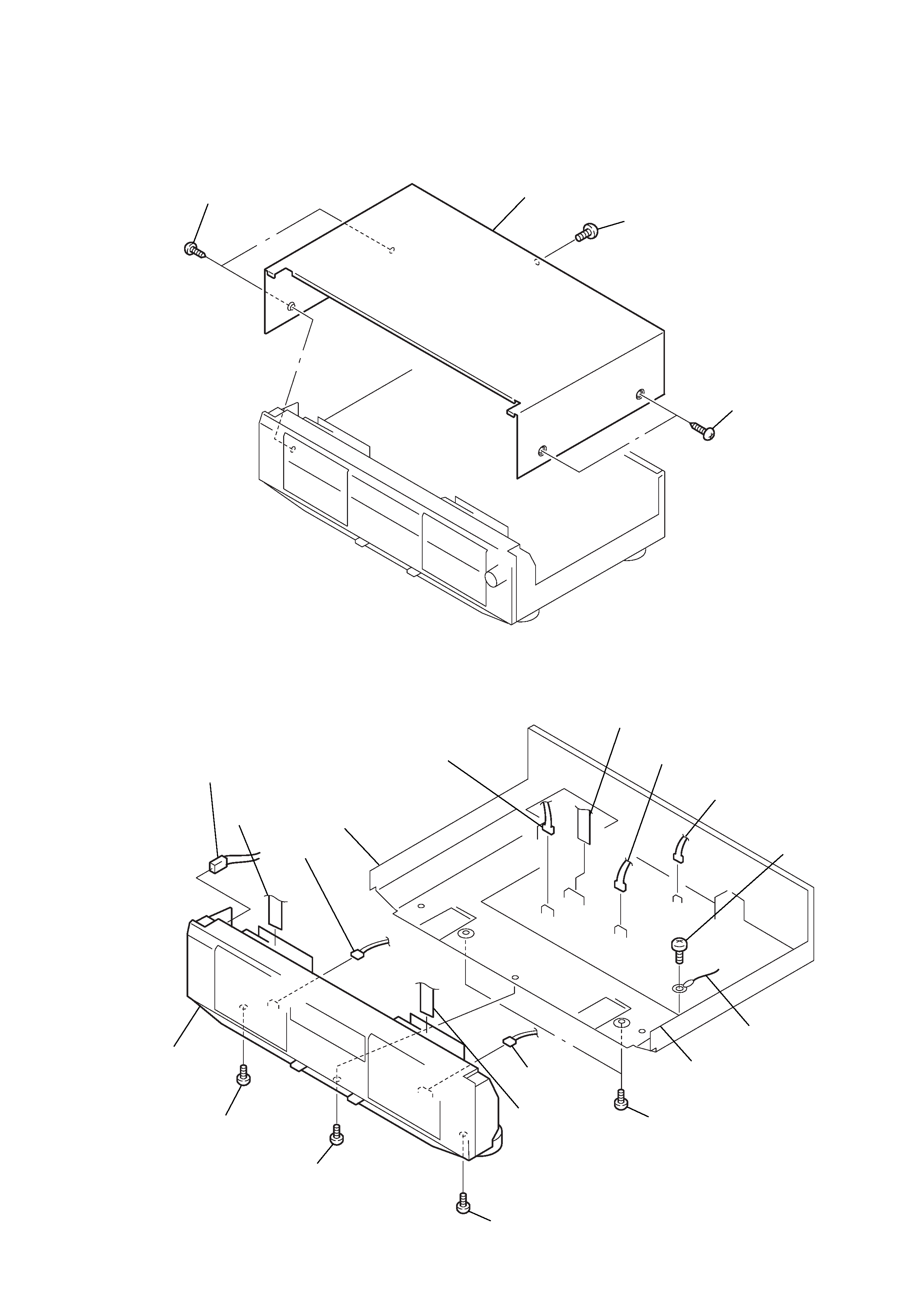
2-1. CASE
2-2. FRONT PANEL ASSEMBLY
1 Screw
(BVTT 3x6)
2 Two Screws
(Case 3 TP2)
3 Two Screws
(Case 3 TP2)
4 Case
!TM Screw
(BVTP 3x8)
!¢ Screw
(BVTP 3x8)
!£ Screw
(BVTP 3x8)
!¶ Two screws
(BVTT 3x6)
!§ Claw
! Claw
!· Front panel assy
9 CN1002
0 CN1003
2 CN807
1 CN5802
3 CN803
4 CNA806
5 Flat type wire
(Deck A)
!¡ CN002
6 Flat type wire
(Deck B)
7 Screw
(BVTP 3x8)
8Wire